EP0903570A2 - Device for driving tubular drill - Google Patents
Device for driving tubular drill Download PDFInfo
- Publication number
- EP0903570A2 EP0903570A2 EP98810873A EP98810873A EP0903570A2 EP 0903570 A2 EP0903570 A2 EP 0903570A2 EP 98810873 A EP98810873 A EP 98810873A EP 98810873 A EP98810873 A EP 98810873A EP 0903570 A2 EP0903570 A2 EP 0903570A2
- Authority
- EP
- European Patent Office
- Prior art keywords
- tool holder
- stop surface
- tool
- hollow drilling
- housing
- Prior art date
- Legal status (The legal status is an assumption and is not a legal conclusion. Google has not performed a legal analysis and makes no representation as to the accuracy of the status listed.)
- Granted
Links
Images


Classifications
-
- B—PERFORMING OPERATIONS; TRANSPORTING
- B23—MACHINE TOOLS; METAL-WORKING NOT OTHERWISE PROVIDED FOR
- B23B—TURNING; BORING
- B23B51/00—Tools for drilling machines
- B23B51/12—Adapters for drills or chucks; Tapered sleeves
-
- G—PHYSICS
- G01—MEASURING; TESTING
- G01N—INVESTIGATING OR ANALYSING MATERIALS BY DETERMINING THEIR CHEMICAL OR PHYSICAL PROPERTIES
- G01N1/00—Sampling; Preparing specimens for investigation
- G01N1/02—Devices for withdrawing samples
- G01N1/04—Devices for withdrawing samples in the solid state, e.g. by cutting
- G01N1/08—Devices for withdrawing samples in the solid state, e.g. by cutting involving an extracting tool, e.g. core bit
-
- B—PERFORMING OPERATIONS; TRANSPORTING
- B23—MACHINE TOOLS; METAL-WORKING NOT OTHERWISE PROVIDED FOR
- B23Q—DETAILS, COMPONENTS, OR ACCESSORIES FOR MACHINE TOOLS, e.g. ARRANGEMENTS FOR COPYING OR CONTROLLING; MACHINE TOOLS IN GENERAL CHARACTERISED BY THE CONSTRUCTION OF PARTICULAR DETAILS OR COMPONENTS; COMBINATIONS OR ASSOCIATIONS OF METAL-WORKING MACHINES, NOT DIRECTED TO A PARTICULAR RESULT
- B23Q7/00—Arrangements for handling work specially combined with or arranged in, or specially adapted for use in connection with, machine tools, e.g. for conveying, loading, positioning, discharging, sorting
- B23Q7/04—Arrangements for handling work specially combined with or arranged in, or specially adapted for use in connection with, machine tools, e.g. for conveying, loading, positioning, discharging, sorting by means of grippers
- B23Q7/046—Handling workpieces or tools
-
- B—PERFORMING OPERATIONS; TRANSPORTING
- B28—WORKING CEMENT, CLAY, OR STONE
- B28D—WORKING STONE OR STONE-LIKE MATERIALS
- B28D1/00—Working stone or stone-like materials, e.g. brick, concrete or glass, not provided for elsewhere; Machines, devices, tools therefor
- B28D1/02—Working stone or stone-like materials, e.g. brick, concrete or glass, not provided for elsewhere; Machines, devices, tools therefor by sawing
- B28D1/04—Working stone or stone-like materials, e.g. brick, concrete or glass, not provided for elsewhere; Machines, devices, tools therefor by sawing with circular or cylindrical saw-blades or saw-discs
- B28D1/041—Working stone or stone-like materials, e.g. brick, concrete or glass, not provided for elsewhere; Machines, devices, tools therefor by sawing with circular or cylindrical saw-blades or saw-discs with cylinder saws, e.g. trepanning; saw cylinders, e.g. having their cutting rim equipped with abrasive particles
-
- Y—GENERAL TAGGING OF NEW TECHNOLOGICAL DEVELOPMENTS; GENERAL TAGGING OF CROSS-SECTIONAL TECHNOLOGIES SPANNING OVER SEVERAL SECTIONS OF THE IPC; TECHNICAL SUBJECTS COVERED BY FORMER USPC CROSS-REFERENCE ART COLLECTIONS [XRACs] AND DIGESTS
- Y10—TECHNICAL SUBJECTS COVERED BY FORMER USPC
- Y10T—TECHNICAL SUBJECTS COVERED BY FORMER US CLASSIFICATION
- Y10T408/00—Cutting by use of rotating axially moving tool
- Y10T408/44—Cutting by use of rotating axially moving tool with means to apply transient, fluent medium to work or product
- Y10T408/45—Cutting by use of rotating axially moving tool with means to apply transient, fluent medium to work or product including Tool with duct
- Y10T408/455—Conducting channel extending to end of Tool
-
- Y—GENERAL TAGGING OF NEW TECHNOLOGICAL DEVELOPMENTS; GENERAL TAGGING OF CROSS-SECTIONAL TECHNOLOGIES SPANNING OVER SEVERAL SECTIONS OF THE IPC; TECHNICAL SUBJECTS COVERED BY FORMER USPC CROSS-REFERENCE ART COLLECTIONS [XRACs] AND DIGESTS
- Y10—TECHNICAL SUBJECTS COVERED BY FORMER USPC
- Y10T—TECHNICAL SUBJECTS COVERED BY FORMER US CLASSIFICATION
- Y10T408/00—Cutting by use of rotating axially moving tool
- Y10T408/65—Means to drive tool
-
- Y—GENERAL TAGGING OF NEW TECHNOLOGICAL DEVELOPMENTS; GENERAL TAGGING OF CROSS-SECTIONAL TECHNOLOGIES SPANNING OVER SEVERAL SECTIONS OF THE IPC; TECHNICAL SUBJECTS COVERED BY FORMER USPC CROSS-REFERENCE ART COLLECTIONS [XRACs] AND DIGESTS
- Y10—TECHNICAL SUBJECTS COVERED BY FORMER USPC
- Y10T—TECHNICAL SUBJECTS COVERED BY FORMER US CLASSIFICATION
- Y10T408/00—Cutting by use of rotating axially moving tool
- Y10T408/89—Tool or Tool with support
- Y10T408/895—Having axial, core-receiving central portion
Definitions
- the invention relates to a drive device for hollow drilling tools according to the preamble of claim 1.
- DE-GM 1 898 626 discloses a hollow drilling tool and a tool holder is known in which the hollow drilling tool can be fixed by means of a positive connection is.
- the tool holder has a blind hole with one from the inner wall of the blind hole projecting radially.
- the reason of the A blind hole is formed by a bottom part.
- the hollow drilling tool is with a Groove arranged on the outside, partially inclined to the longitudinal axis of the hollow drilling tool.
- the hollow drilling tool can be used for bores for dowels or through openings for Create pipes in hard surfaces. In the production of such bores or through-openings occur in the interior of the hollow drilling tool must be removed from the hollow drilling tool from time to time.
- the Hollow drilling tools are usually equipped with cutting edges in the end area on the drilling direction are provided, which the tubular support body of the hollow drilling tool in radial Exceed direction on both sides. Since the outside diameter of the core in is essentially the same size as an inner diameter formed by the cutting edges but is smaller than the inner diameter of the tubular support body Removal of the cores from the hollow drilling tool by cutting opposite end of the tubular support body more easily possible.
- the invention has for its object to a drive device for hollow drilling tools create, in the drilling cores against the drilling direction from the hollow drilling tool can be removed quickly, safely and easily without the need for the hollow drilling tool from the one connected to the drive unit Tool holder must be removed
- a drive device for hollow drilling tools which the features stated in the characterizing section of claim 1 having. Because a base part can be removed from the tool holder there is the possibility that drilling cores that are involved in the production of bores or Through openings arise through the tool holder against the Drilling direction can be removed from this without the hollow drilling tool from a tool holder, for example, partially protruding into the drive device must be removed.
- the bottom part is part of the housing, for example.
- the bottom part is expediently from a stop surface of the tool holder, which is perpendicular to its main axis and from remaining part of the tool holder is removable.
- the stop surface is for example, can be displaced so far along the main axis of the tool holder, that the distance between the tool holder and the stop surface is larger than the length of the core to be removed.
- An unimpeded removal of the drill core against the drilling direction from the Tool holder is preferably carried out by means of a stop surface from the Axial projection of the clear width of the hollow drilling tool is removable. This can for example in the form that this is from the side of the tool holder Will get removed.
- a quick insertion or removal of one with an insertion end if necessary Connected hollow drilling tool in the tool holder is for example thereby achieved that the hollow drilling tool against the drilling direction facing end area of the tool holder inserted into this and in Drilling direction is shifted until the hollow drilling tool or its insertion end a stop edge of the tool holder pointing against the drilling direction Plant arrives.
- the axial fixation of the hollow drilling tool in the tool holder expediently takes place by means of one of the entire axial projection of the Entire hollow drilling tool removable, rotatable stop surface.
- the rotatable stop surface is, for example, in a handle that as separate component is formed and a clamping device with the housing in Connection is established.
- the displaceability of the stop surface can advantageously be achieved by Pivoting take place around the tensioning device, which is essentially an essentially forms axis parallel to the main axis of the tool holder.
- the jig has, for example, a rotatable eccentric, with the help of which The handle can be fixed or detached from the housing so that the handle can be pivoted or the stop surface can take place.
- the rotatable stop surface can follow a further proposal of the invention a handle can be arranged, which is designed as a separate component and a Joint is connected to the housing.
- the axis of this joint extends expediently in a perpendicular to the main axis of the tool holder Level, so that the removal of the stop surface by pivoting about the hinge axis or in a substantially parallel to the main axis Level is done.
- the stop surface is preferably from passes through a coolant channel which in connection with a coolant supply device stands, the outlet mouth of the coolant channel in one of the Stop plane formed lies.
- the coolant supply device can, for example, be an externally arranged device be with a pump with the coolant via a coolant line to the coolant channel is fed.
- a shutdown device interrupting the coolant supply device arranged, which can be activated when removing the stop surface.
- this switch-off device it is, for example, a solenoid valve in the coolant line installed and the coolant supply device to the hollow drilling tool releases or pauses.
- the stop surface is removed from the rest of the tool holder and the drive device is turned upside down so that it is inside the hollow drilling tool existing drill core can slip out.
- a rotary movement on the tool holder interrupting switch-off device can be activated.
- the shutdown device it is, for example, a connection to the electrical connecting line standing electrical switch at which contact is broken as soon as the stop surface is removed from the rest of the tool holder.
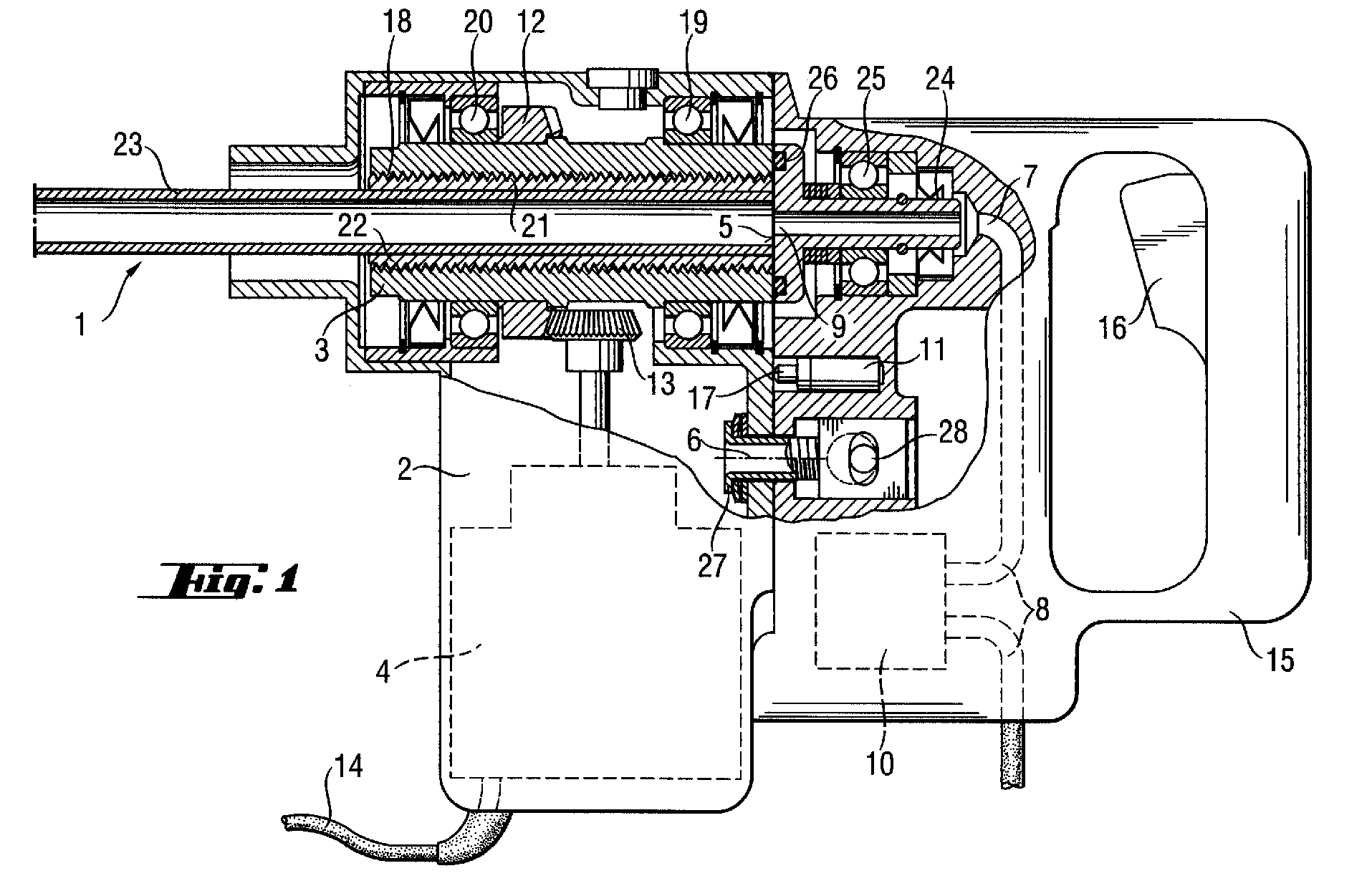
- FIGS. 1 and 2 differ only in the type of pivotability
- the same reference numerals are used for both figures.
- the only difference between the two figures is the design the pivotability of the stop surface.
- this pivotability is used Axis 6 and a joint 30 in FIG. 2.
- FIGS. 1 and 2 show one Housing 2, a handle 15 with operating switch 16, one in the housing 2 rotatably arranged tool holder 3 and a hollow drilling tool 1.
- An electrical drive unit 4 with which the Tool holder is rotatable.
- the drive unit 4 is via a electrical connecting line 14 can be connected to an external power source.
- the drive unit 4 has an output shaft at its free end helical-toothed pinion 13 is arranged, which has a helical-toothed gear 12 interacts positively. This helical gear 12 is in a fixed connection with the tool holder 3.
- the tool holder 3 has a longitudinal axis that is perpendicular to the longitudinal axis of the Drive unit 4 runs.
- the rotatable mounting of the tool holder 3 within the housing 2 serve two spaced apart bearings 19, 20.
- Die Tool holder 3 has a central through hole within which the Hollow drilling tool 1 can be fixed.
- the inner wall of the through hole is with provided with an internal thread 21 which is form-fitting with an external thread 18 an insertion end 22 cooperates.
- the insertion end 22 is part of the hollow drilling tool 1 and is fixed to a tubular support body 23 of the hollow drilling tool 1 connected.
- the outlet mouth 9 is located in the plane formed by the stop surface 5 one through part of the handle 15 and the cylindrical guide portion 24 extending coolant channel 7, which does not have a coolant line 8 with a Coolant supply device shown is connected.
- the coolant line 8 is interrupted by a shutdown device 10 in the form of a solenoid valve, which the Supply of coolant stops when the stop surface 5 from the rest of the Tool holder 3 is removed.
- the stop surface 5 has a circumferential recess in the peripheral region on, which serves to accommodate a sealing element in the form of an O-ring.
- This Sealing element 26 presses against the free end face of the tool holder 3 and ensures that coolant flowing through the coolant channel 7 to the hollow drilling tool 1 is supplied, can not reach the bearings 19, 20 of the tool holder 3.
- the solenoid valve is connected, for example, to the actuation switch 16. If the operating switch 16 is not pressed, the solenoid valve blocks the Coolant supply.
- a switch-off device 11 in the form of an electrical switch arranged with which the electrical connection line 14 and thus the power supply to the electric drive unit 4 is interrupted when the stop surface 5 from remaining part of the tool holder 3 is removed.
- the removal of the stop surface 5 from the remaining part of the tool holder 3 takes place 1 by pivoting by an essentially axis 6 of a clamping device running parallel to the main axis of the tool holder 3, via which the handle 15 can be fixed on the housing 2.
- the axis 6 will formed by a arranged between the handle 15 and the housing 2, spring-loaded clamping screw 27, which can be tightened with an eccentric 28.
- Eccentric 28 is connected to a tension lever, not shown.
- the handle 15 by a small distance from the Housing 2 can be lifted against the drilling direction, so that between the stop surface 5 and the tool holder 3 acting sealing element 26 when pivoting of the handle 15 relative to the housing 2 from the tool holder 3 is spaced.
- the electrical switch arranged on the handle 15 has one spring-loaded contact pin 17, which when pivoting the handle 15 in a the clear width of the hollow drilling tool 1 or the axial projection surface of the entire hollow drilling tool 1 releasing position of the housing 2 no longer is biased and thus breaks a contact, so that the electrical Drive unit 4 is no longer supplied with electricity.
- the removal of the stop surface 5 from the remaining part of the tool holder 3 takes place 2 by swiveling the stop surface 5 in one running essentially parallel to the main axis of the tool holder 3 Level.
- the drive device has between the handle 15 and the Housing 2 has a joint 30 with an axis of rotation 29 which is parallel to one of the Stop surface 5 formed level extends.
Landscapes
- Engineering & Computer Science (AREA)
- Mechanical Engineering (AREA)
- Analytical Chemistry (AREA)
- Pathology (AREA)
- Physics & Mathematics (AREA)
- Biochemistry (AREA)
- General Health & Medical Sciences (AREA)
- General Physics & Mathematics (AREA)
- Immunology (AREA)
- Chemical & Material Sciences (AREA)
- Life Sciences & Earth Sciences (AREA)
- Mining & Mineral Resources (AREA)
- Health & Medical Sciences (AREA)
- Processing Of Stones Or Stones Resemblance Materials (AREA)
- Drilling And Boring (AREA)
- Earth Drilling (AREA)
Abstract
Das Antriebsgerät für Hohlbohrwerkzeuge (1) weist ein Gehäuse (2), eine gegenüber
dem Gehäuse (2) drehbar gelagerte Werkzeugaufnahme (3) und eine Antriebseinheit (4)
auf, mit der die Werkzeugaufnahme (3) in Drehbewegung versetzbar ist. Die Werkzeugaufnahme
(3) weist eine ein Bodenteil bildende, senkrecht zur Hauptachse der Werkzeugaufnahme
(3) verlaufende Anschlagfläche (5) auf, die vom restlichen Teil der Werkzeugaufnahme
(3) entfembar und gegenüber dem Gehäuse (2) drehbar gelagert ist.
Description
Die Erfindung betrifft ein Antriebsgerät für Hohlbohrwerkzeuge gemäss dem Oberbegriff
des Patentanspruchs 1.The invention relates to a drive device for hollow drilling tools according to the preamble
of
Aus dem DE-GM 1 898 626 ist ein Hohlbohrwerkzeug und eine Werkzeugaufnahme bekannt, in der das Hohlbohrwerkzeug mittels einer formschlüssigen Verbindung festlegbar ist. Die Werkzeugaufnahme weist eine Sacklochbohrung mit einem von der Innenwandung der Sacklochbohrung radial abragenden Vorsprung auf. Der Grund der Sacklochbohrung wird von einem Bodenteil gebildet. Das Hohlbohrwerkzeug ist mit einer an der Aussenseite angeordneten Nut versehen, die teilweise geneigt zur Längsachse des Hohlbohrwerkzeuges verläuft.DE-GM 1 898 626 discloses a hollow drilling tool and a tool holder is known in which the hollow drilling tool can be fixed by means of a positive connection is. The tool holder has a blind hole with one from the inner wall of the blind hole projecting radially. The reason of the A blind hole is formed by a bottom part. The hollow drilling tool is with a Groove arranged on the outside, partially inclined to the longitudinal axis of the hollow drilling tool.
Zum Verbinden beider Teile werden diese zusammengesteckt und gegenseitig verdreht, bis ein entgegen der Bohrrichtung weisendes freies Ende des Hohlbohrwerkzeuges an dem in Bohrrichtung weisenden Grund der Sacklochbohrung zur Anlage gelangt. Mit Hilfe des Hohlbohrwerkzeuges lassen sich Bohrungen für Dübel oder Durchtrittsöffnungen für Rohrleitungen in harten Untergründen erstellen. Bei der Herstellung derartiger Bohrungen bzw. Durchtrittsöffnungen fallen im Innern des Hohlbohrwerkzeuges Bohrkerne an, die von Zeit zu Zeit aus dem Hohlbohrwerkzeug entfernt werden müssen. Die Hohlbohrwerkzeuge sind im bohrrichtungsseitigen Endbereich in der Regel mit Schneiden versehen sind, die den rohrförmigen Trägerkörper des Hohlbohrwerkzeuges in radialer Richtung zu beiden Seiten hin überragen. Da der Aussendurchmesser des Bohrkernes im wesentlichen gleich gross ist wie ein von den Schneiden gebildeter Innendurchmesser aber kleiner ist als der Innendurchmesser des rohrförmigen Trägerkörpers ist eine Entnahme der Bohrkerne aus dem Hohlbohrwerkzeug durch das den Schneiden gegenüberliegende Ende des rohrförmigen Trägerkörpers leichter möglich. To connect both parts, they are plugged together and twisted together, until a free end of the hollow drilling tool pointing against the drilling direction the bottom of the blind hole pointing in the drilling direction comes to the system. With help The hollow drilling tool can be used for bores for dowels or through openings for Create pipes in hard surfaces. In the production of such bores or through-openings occur in the interior of the hollow drilling tool must be removed from the hollow drilling tool from time to time. The Hollow drilling tools are usually equipped with cutting edges in the end area on the drilling direction are provided, which the tubular support body of the hollow drilling tool in radial Exceed direction on both sides. Since the outside diameter of the core in is essentially the same size as an inner diameter formed by the cutting edges but is smaller than the inner diameter of the tubular support body Removal of the cores from the hollow drilling tool by cutting opposite end of the tubular support body more easily possible.
Um eine Entnahme des Bohrkemes aus dem Hohlbohrwerkzeug in der vorbeschriebenen Weise durchführen zu können, ist es notwendig, dass das bekannte Hohlbohrwerkzeug und die Werkzeugaufnahme voneinander getrennt werden. Dieser Vorgang ist sehr zeitaufwendig. Zudem bedarf es eines entprechenden Werkzeuges, mit dem der rohrförmige Trägerkörper fest umgriffen werden kann, um diesen gegenüber der Werkzeugaufnahme verdrehen zu können. Insbesondere nach einer längeren Bearbeitung ist das Hohlbohrwerkzeug derart erwärmt, dass die Entnahme eines gelösten Hohlbohrwerkzeuges aus der Werkzeugaufnahme mit blossen Händen nicht möglich ist.In order to remove the core from the hollow drilling tool in the To be able to carry out the manner described above, it is necessary that the known Hollow drilling tool and the tool holder are separated from each other. This The process is very time consuming. A corresponding tool is also required with which can be firmly gripped around the tubular support body to make it opposite the To be able to twist the tool holder. Especially after a long one Processing, the hollow drilling tool is heated such that the removal of a Loosened hollow drilling tool from the tool holder with bare hands is possible.
Der Erfindung liegt die Aufgabe zugrunde, ein Antriebsgerät für Hohlbohrwerkzeuge zu schaffen, bei dem Bohrkerne entgegen der Bohrrichtung aus dem Hohlbohrwerkzeug schnell, sicher und einfach entnommen werden können, ohne dass das Hohlbohrwerkzeug aus der mit dem Antriebsgerät in Verbindung stehenden Werkzeugaufnahme entnommen werden mussThe invention has for its object to a drive device for hollow drilling tools create, in the drilling cores against the drilling direction from the hollow drilling tool can be removed quickly, safely and easily without the need for the hollow drilling tool from the one connected to the drive unit Tool holder must be removed
Die Lösung dieser Aufgabe erfolgt durch ein Antriebsgerät für Hohlbohrwerkzeuge,
welches die im kennzeichnenden Abschnitt des Patentanspruchs 1 angeführten Merkmale
aufweist. Durch die entfernbarkeit eines Bodenteiles von der Werkzeugaufnahme
ergibt sich die Möglichkeit, dass Bohrkeme, die bei der Herstellung von Bohrungen bzw.
Durchtrittsöffnungen entstehen durch die Werkzeugaufnahme hindurch entgegen der
Bohrrichtung aus dieser entnommen werden können, ohne dass das Hohlbohrwerkzeug
aus einer beispielsweise teilweise in das Antriebsgerät ragenden Werkzeugaufnahme
entnommen werden muss. Das Bodenteil ist beispielsweise ein Teil des Gehäuses.This task is solved by a drive device for hollow drilling tools,
which the features stated in the characterizing section of
Insbesondere bei Hohlbohrwerkzeugen, die entgegen der Bohrrichtung beispielsweise mittels einer Gewindeverbindung in die Werkzeugaufnahme einsetzbar sind, brauchen ein Bodenteil, gegen das sie laufen können, um eine Verklemmung zwischen den Flanken der Gewindeverbindung erreichen zu können. Damit keine Reibung zwischen dem Bodenteil und einer entgegen der Bohrrichtung weisenden Stimseite des Hohlbohrwerkzeuges entsteht, wenn sich das Hohlbohrwerkzeug dreht und damit eine Entfemung des Bohrkemes entgegen der Bohrrichtung durch die Werkzeugaufnahme hindurch möglich ist, ist zweckmässigerweise das Bodenteil von einer Anschlagfläche der Werkzeugaufnahme gebildet, die senkrecht zu dessen Hauptachse verläuft und vom restlichen Teil der Werkzeugaufnahme entfernbar ist. Die Anschlagfläche ist beispielsweise entlang der Hauptachse des Werkzeugaufnahme derart weit versetzbar, dass der Abstand zwischen der Werkzeugaufnahme und der Anschlagfläche grösser ist als die Länge des zu entnehmenden Bohrkemes.In particular in the case of hollow drilling tools, for example contrary to the drilling direction can be inserted into the tool holder by means of a threaded connection a floor part against which they can run to prevent jamming between the To be able to reach flanks of the threaded connection. So that there is no friction between the bottom part and an opposite end of the Hollow drilling tool is created when the hollow drilling tool rotates and thus a Removal of the drilling core against the drilling direction through the tool holder is possible, the bottom part is expediently from a stop surface of the tool holder, which is perpendicular to its main axis and from remaining part of the tool holder is removable. The stop surface is for example, can be displaced so far along the main axis of the tool holder, that the distance between the tool holder and the stop surface is larger than the length of the core to be removed.
Eine ungehinderte Entnahme des Bohrkemes entgegen der Bohrrichtung aus der Werkzeugaufnahme erfolgt vorzugsweise mittels einer Anschlagfläche die aus der Axialprojektion der lichten Weite des Hohlbohrwerkzeuges entfernbar ist. Dies kann beispielsweise in der Form erfolgen, das diese seitlich von der Werkzeugaufnahme entfernt wird.An unimpeded removal of the drill core against the drilling direction from the Tool holder is preferably carried out by means of a stop surface from the Axial projection of the clear width of the hollow drilling tool is removable. This can for example in the form that this is from the side of the tool holder Will get removed.
Ein schnelles Einsetzen bzw. Entfemen eines gegebenenfalls mit einem Einsteckende in Verbindung stehenden Hohlbohrwerkzeuges in die Werkzeugaufnahme wird beispielsweise dadurch erreicht, dass das Hohlbohrwerkzeug an einem entgegen der Bohrrichtung weisenden Endbereich der Werkzeugaufnahme in diese eingesetzt und in Bohrrichtung verschoben wird, bis das Hohlbohrwerkzeug bzw. dessen Einsteckende an einer entgegen der Bohrrichtung weisenden Anschlagkante der Werkzeugaufnahme zur Anlage gelangt. Die axiale Festlegung des Hohlbohrwerkzeuges in der Werkzeugaufnahme erfolgt zweckmässigerweise mittels einer aus der gesamten Axialprojektion des gesamten Hohlbohrwerkzeuges entfernbaren, drehbaren Anschlagfläche.A quick insertion or removal of one with an insertion end if necessary Connected hollow drilling tool in the tool holder is for example thereby achieved that the hollow drilling tool against the drilling direction facing end area of the tool holder inserted into this and in Drilling direction is shifted until the hollow drilling tool or its insertion end a stop edge of the tool holder pointing against the drilling direction Plant arrives. The axial fixation of the hollow drilling tool in the tool holder expediently takes place by means of one of the entire axial projection of the Entire hollow drilling tool removable, rotatable stop surface.
Die drehbare Anschlagfläche befindet sich beispielsweise in einem Handgriff, der als separates Bauteil ausgebildet ist und über eine Spannvorrichtung mit dem Gehäuse in Verbindung steht. Die Versetzbarkeit der Anschlagfläche kann vorteilhafterweise durch Verschwenken um die Spannvorrichtung erfolgen, die zum Teil eine im wesentlichen parallel zur Hauptachse der Werkzeugaufnahme verlaufende Achse bildet. Die Spannvorrichtung weist beispielsweise einen drehbaren Exzenter auf, mit dessen Hilfe der Handgriff am Gehäuse festlegbar bzw. lösbar ist damit ein Verschwenken des Handgriffes bzw. der Anschlagfläche erfolgen kann.The rotatable stop surface is, for example, in a handle that as separate component is formed and a clamping device with the housing in Connection is established. The displaceability of the stop surface can advantageously be achieved by Pivoting take place around the tensioning device, which is essentially an essentially forms axis parallel to the main axis of the tool holder. The jig has, for example, a rotatable eccentric, with the help of which The handle can be fixed or detached from the housing so that the handle can be pivoted or the stop surface can take place.
Die drehbare Anschlagfläche kann einem weiteren Vorschlag der Erfindung folgend an einem Handgriff angeordnet sein, der als separates Bauteil ausgebildet ist und über ein Gelenk mit dem Gehäuse in Verbindung steht. Die Achse dieses Gelenkes erstreckt sich zweckmässigerweise in einer senkrecht zur Hauptachse der Werkzeugaufnahme verlaufenden Ebene, so dass das Entfemen der Anschlagfläche durch ein Verschwenken um die Gelenkachse bzw. in einer im wesentlichen parallel zur Hauptachse stehenden Ebene erfolgt. The rotatable stop surface can follow a further proposal of the invention a handle can be arranged, which is designed as a separate component and a Joint is connected to the housing. The axis of this joint extends expediently in a perpendicular to the main axis of the tool holder Level, so that the removal of the stop surface by pivoting about the hinge axis or in a substantially parallel to the main axis Level is done.
Bei der Bearbeitung von harten Untergrundmaterialien entstehen sehr hohe Temperaturen im Bereich der Schneiden des Hohlbohrwerkzeuges. Ein schnelles Verschleissen dieser Schneiden wird mit Kühlmittel verhindert, das während des Bohrvorganges dem Hohlbohrwerkzeug zugeführt wird. Um dieses Kühlmittel dem Innem des Hohlbohrwerkzeuges zuführen zu können, ist die Anschlagfläche vorzugsweise von einem Kühlmittelkanal durchsetzt, der mit einer Kühlmittelzuführeinrichtung in Verbindung steht, wobei die Austrittsmündung des Kühlmittelkanals in einer von der Anschlagfläche gebildeten Ebene liegt.When processing hard surface materials, very high ones arise Temperatures in the area of the cutting edges of the hollow drilling tool. A quick wear and tear this cutting is prevented with coolant during the drilling process is fed to the hollow drilling tool. To this coolant the inside of the To be able to supply hollow drilling tool, the stop surface is preferably from passes through a coolant channel which in connection with a coolant supply device stands, the outlet mouth of the coolant channel in one of the Stop plane formed lies.
Die Kühlmittelzuführeinrichtung kann beispielsweise eine extem angeordnete Vorrichtung mit einer Pumpe sein, mit der Kühlmittel über eine Kühlmittelleitung dem Kühlmittelkanal zugeführt wird. Im Bereich des Gehäuses bzw. des Handgriffes ist vorteilhafterweise eine die Kühlmittelzuführeinrichtung unterbrechende Abschalteinrichtung angeordnet, die beim Entfemen der Anschlagfläche aktivierbar ist. Bei dieser Abschalteinrichtung handelt es sich beispielsweise um ein Magnetventil, das in der Kühlmittelleitung eingebaut und die Kühlmittelzuführeinrichtung zum Hohlbohrwerkzeug freigibt oder unterbricht.The coolant supply device can, for example, be an externally arranged device be with a pump with the coolant via a coolant line to the coolant channel is fed. In the area of the housing or the handle is advantageous a shutdown device interrupting the coolant supply device arranged, which can be activated when removing the stop surface. With this switch-off device it is, for example, a solenoid valve in the coolant line installed and the coolant supply device to the hollow drilling tool releases or pauses.
Zum Entfemen eines Bohrkemes aus dem Innem des Hohlbohrwerkzeuges ist es von Vorteil, wenn die Anschlagfläche vom restlichen Teil der Werkzeugaufnahme entfernt und das Antriebsgerät auf den Kopf gestellt wird, damit der sich im Innem des Hohlbohrwerkzeuges befindliche Bohrkem herausrutschen kann. Um Beschädigungen umliegender Bauteile oder Gegenstände durch die Schneiden des Hohlbohrwerkzeuges verhindem zu können, wenn das Antriebsgerät auf den Kopf gestellt wird, ist vorzugsweise beim Entfernen der Anschlagfläche eine die Drehbewegung auf die Werkzeugaufnahme unterbrechende Abschalteinrichtung aktivierbar. Bei der Abschalteinrichtung handelt es sich beispielsweise um einen mit der elektrischen Verbindungsleitung in Verbindung stehenden elektrischen Schalter, bei dem ein Kontakt unterbrochen wird, sobald die Anschlagfläche vom restlichen Teil der Werkzeugaufnahme entfernt wird.To remove a core from the inside of the hollow drilling tool, it is from Advantage if the stop surface is removed from the rest of the tool holder and the drive device is turned upside down so that it is inside the hollow drilling tool existing drill core can slip out. To damage surrounding components or objects by cutting the hollow drilling tool Preventing when the drive device is turned upside down is preferred when removing the stop surface, a rotary movement on the tool holder interrupting switch-off device can be activated. At the shutdown device it is, for example, a connection to the electrical connecting line standing electrical switch at which contact is broken as soon as the stop surface is removed from the rest of the tool holder.
Die Erfindung wird anhand von Zeichnungen, die ein Ausführungsbeispiel wiedergeben näher erläutert. Es zeigen:
- Fig. 1
- ein erfindungsgemässes Antriebsgerät für Hohlbohrwerkzeuge, teilweise geschnitten; die Anschlagfläche ist um eine im wesentlichen parallel zur Hauptachse der Werkzeugaufnahme verschwenkbar;
- Fig. 2
- ein weiteres Antriebsgerät für Hohlbohrwerkzeuge, teilweise geschnitten, die Antriebsfläche ist in einer im wesentlichen parallel zur Hauptachse stehenden Ebene verschwenkbar.
- Fig. 1
- an inventive drive device for hollow drilling tools, partially cut; the stop surface can be pivoted about a substantially parallel to the main axis of the tool holder;
- Fig. 2
- Another drive device for hollow drilling tools, partially cut, the drive surface can be pivoted in a plane substantially parallel to the main axis.
Da sich die Fig. 1 und 2 nur durch die Art der Verschwenkbarkeit unterscheiden werden aus Gründen der Vereinfachung für beide Figuren die gleichen Bezugszeichen verwendet. Der einzige Unterschied zwischen beiden Figuren besteht in der Ausgestaltung der Verschwenkbarkeit der Anschlagfläche. In Fig. 1 dient dieser Verschwenkbarkeit eine Achse 6 und in der Fig. 2 ein Gelenk 30.Since FIGS. 1 and 2 differ only in the type of pivotability For the sake of simplicity, the same reference numerals are used for both figures. The only difference between the two figures is the design the pivotability of the stop surface. In Fig. 1 this pivotability is used Axis 6 and a joint 30 in FIG. 2.
Die in den Fig. 1 und 2 dargestellten Antriebsgeräte für Hohlbohrwerkzeuge zeigen ein
Gehäuse 2, einen Handgriff 15 mit Betätigungsschalter 16, eine in dem Gehäuse 2
drehbar angeordnete Werkzeugaufnahme 3 und ein Hohlbohrwerkzeug 1.The drive devices for hollow drilling tools shown in FIGS. 1 and 2 show one
Innerhalb des Gehäuses 2 befindet sich eine elektrische Antriebseinheit 4, mit der die
Werkzeugaufnahme in Drehbewegung versetzbar ist. Die Antriebseinheit 4 ist über eine
elektrische Verbindungsleitung 14 mit einer extemen Stromquelle in Verbindung bringbar.
Die Antriebseinheit 4 verfügt über eine Abtriebswelle, an deren freien Ende ein
schrägverzahntes Ritzel 13 angeordnet ist, das mit einem schrägverzahnten Zahnrad 12
formschlüssig zusammenwirkt. Dieses schrägverzahnte Zahnrad 12 steht in fester Verbindung
mit der Werkzeugaufnahme 3.An electrical drive unit 4, with which the
Tool holder is rotatable. The drive unit 4 is via a
Die Werkzeugaufnahme 3 besitzt eine Längsachse, die senkrecht zur Längsachse der
Antriebseinheit 4 verläuft. Der drehbaren Lagerung der Werkzeugaufnahme 3 innerhalb
des Gehäuses 2 dienen zwei im Abstand voneinander angeordnete Lager 19, 20. Die
Werkzeugaufnahme 3 weist eine zentrale Durchgangsbohrung auf, innerhalb der das
Hohlbohrwerkzeug 1 festlegbar ist. Die Innenwandung der Durchgangsbohrung ist mit
einem Innengewinde 21 versehen, das formschlüssig mit einem Aussengewinde 18
eines Einsteckendes 22 zusammenwirkt. Das Einsteckende 22 ist Teil des Hohlbohrwerkzeuges
1 und ist fest mit einem rohrförmigen Trägerkörper 23 des Hohlbohrwerkzeuges
1 verbunden.The tool holder 3 has a longitudinal axis that is perpendicular to the longitudinal axis of the
Drive unit 4 runs. The rotatable mounting of the tool holder 3 within
the
Als axialer Anschlag beim Eindrehen des Hohlbohrwerkzeuges 1 entgegen der Bohrrichtung
in die Werkzeugaufnahme 3 dient eine senkrecht zur Längsachse des Hohlbohrwerkzeuges
1 verlaufende Anschlagfläche 5, die drehbar an dem Handgriff 15
angeordnet ist. Entgegen der Bohrrichtung schliesst sich an die drehbare Anschlagfläche
5 ein zylindrischer Führungsbereich 24 an, der ein sich in einer sacklochartigen Ausnehmung
des Handgriffes 15 angeordnetes Lager 25 durchsetzt.As an axial stop when screwing in the
In der von der Anschlagfläche 5 gebildeten Ebene befindet sich die Austrittsmündung 9
eines sich durch einen Teil des Handgriffes 15 und den zylindrischen Führungsbereich
24 erstreckenden Kühlmittelkanals 7, der über eine Kühlmittelleitung 8 mit einer nicht
dargestellten Kühlmittelzuführeinrichtung in Verbindung steht. Die Kühlmittelleitung 8 ist
von einer Abschalteinrichtung 10 in Form eines Magnetventils unterbrochen, das die
Zufuhr von Kühlmittel unterbricht, wenn die Anschlagfläche 5 vom restlichen Teil der
Werkzeugaufnahme 3 entfernt wird.The outlet mouth 9 is located in the plane formed by the stop surface 5
one through part of the
Die Anschlagfläche 5 weist im Umfangsbereich eine umlaufend ausgebildete Vertiefung
auf, die der Aufnahme eines Dichtungselementes in Form eines O-Ringes dient. Dieses
Dichtungselement 26 drückt gegen die freie Stimseite der Werkzeugaufnahme 3 und
sorgt dafür, dass Kühlmittel, das durch den Kühlmittelkanal 7 dem Hohlbohrwerkzeug 1
zugeführt wird, nicht zu den Lagern 19, 20 der Werkzeugaufnahme 3 gelangen kann.
Das Magnetventil steht beispielsweise mit dem Betätigungsschalter 16 in Verbindung.
Wenn der Betätigungsschalter 16 nicht gedrückt wird, dann sperrt das Magnetventil die
Kühlmittelzufuhr.The stop surface 5 has a circumferential recess in the peripheral region
on, which serves to accommodate a sealing element in the form of an O-ring. This
An dem Handgriff 15 ist eine Abschalteinrichtung 11 in Form eines elektrischen Schalters
angeordnet, mit dem die elektrische Verbindungsleitung 14 und somit die Stromzufuhr
zur elektrischen Antriebseinheit 4 unterbrochen wird, wenn die Anschlagfläche 5 vom
restlichen Teil der Werkzeugaufnahme 3 entfernt wird.On the
Die Entfemung der Anschlagfläche 5 vom restlichen Teil der Werkzeugaufnahme 3 erfolgt
bei dem Antriebsgerät gemäss Fig. 1 durch Verschwenken um eine im wesentlichen
parallel zur Hauptachse der Werkzeugaufnahme 3 verlaufende Achse 6 einer Spannvorrichtung,
über die der Handgriff 15 an dem Gehäuse 2 festlegbar ist. Die Achse 6 wird
gebildet von einer zwischen dem Handgriff 15 und dem Gehäuse 2 angeordneten,
federbelasteten Spannschraube 27, die mit einem Exzenter 28 festziehbar ist. Der
Exzenter 28 steht mit einem nicht dargestellten Spannhebel in Verbindung. Im gelösten
Zustand der Spannvorrichtung ist der Handgriff 15 um einen geringen Weg von dem
Gehäuse 2 entgegen der Bohrrichtung abhebbar, so dass das zwischen der Anschlagfläche
5 und der Werkzeugaufnahme 3 wirkende Dichtungselement 26 beim Verschwenken
des Handgriffes 15 gegenüber dem Gehäuse 2 von der Werkzeugaufnahme
3 beabstandet ist. Der an dem Handgriff 15 angeordnete elektrische Schalter weist einen
federbelasteten Kontaktstift 17 auf, der beim Verschwenken des Handgriffes 15 in eine
die lichte Weite des Hohlbohrwerkzeuges 1 bzw. die axiale Projektionsfläche des
gesamten Hohlbohrwerkzeuges 1 freigebende Position von dem Gehäuse 2 nicht mehr
vorgespannt wird und somit einen Kontakt unterbricht, so dass der elektrischen
Antriebseinheit 4 kein Strom mehr zugeführt wird.The removal of the stop surface 5 from the remaining part of the tool holder 3 takes
Die Entfemung der Anschlagfläche 5 vom restlichen Teil der Werkzeugaufnahme 3 erfolgt
bei dem Antriebsgerät gemäss Fig. 2 durch Verschwenken der Anschlagfläche 5 in
einer im wesentlichen parallel zur Hauptachse der Werkzeugaufnahme 3 verlaufenden
Ebene. Das Antriebsgerät weist zu diesem Zweck zwischen dem Handgriff 15 und dem
Gehäuse 2 ein Gelenk 30 mit einer Drehachse 29 auf, die sich parallel zu einer von der
Anschlagfläche 5 gebildeten Ebene erstreckt.The removal of the stop surface 5 from the remaining part of the tool holder 3 takes
Claims (9)
Applications Claiming Priority (2)
| Application Number | Priority Date | Filing Date | Title |
|---|---|---|---|
| DE19740464A DE19740464A1 (en) | 1997-09-15 | 1997-09-15 | Drive device for hollow drilling tools |
| DE19740464 | 1997-09-15 |
Publications (3)
| Publication Number | Publication Date |
|---|---|
| EP0903570A2 true EP0903570A2 (en) | 1999-03-24 |
| EP0903570A3 EP0903570A3 (en) | 2004-11-03 |
| EP0903570B1 EP0903570B1 (en) | 2006-07-26 |
Family
ID=7842361
Family Applications (1)
| Application Number | Title | Priority Date | Filing Date |
|---|---|---|---|
| EP98810873A Expired - Lifetime EP0903570B1 (en) | 1997-09-15 | 1998-09-02 | Device for driving tubular drill |
Country Status (7)
| Country | Link |
|---|---|
| US (1) | US5951217A (en) |
| EP (1) | EP0903570B1 (en) |
| JP (1) | JP4205218B2 (en) |
| KR (1) | KR19990029344A (en) |
| AT (1) | ATE334381T1 (en) |
| DE (2) | DE19740464A1 (en) |
| ES (1) | ES2270499T3 (en) |
Cited By (1)
| Publication number | Priority date | Publication date | Assignee | Title |
|---|---|---|---|---|
| CN110524025A (en) * | 2019-09-24 | 2019-12-03 | 北华大学 | A deep hole drilling jig for small orthopedic cannulated screws |
Families Citing this family (9)
| Publication number | Priority date | Publication date | Assignee | Title |
|---|---|---|---|---|
| DE19846712A1 (en) * | 1998-10-09 | 2000-04-13 | Hilti Ag | Device for processing a hard surface |
| US6149356A (en) * | 1999-04-15 | 2000-11-21 | China Pneumatic Corporation | Portable pneumatic tool assembled with module units |
| US6299394B1 (en) * | 2000-02-28 | 2001-10-09 | Stojan Stojanovski | Milling tool holder |
| JP2005231156A (en) * | 2004-02-19 | 2005-09-02 | Hitachi Koki Co Ltd | Drilling device and compressor |
| DE102007038555A1 (en) * | 2007-08-16 | 2009-02-19 | Hilti Aktiengesellschaft | Electric hand tool |
| US20100021251A1 (en) * | 2008-07-23 | 2010-01-28 | Horton M Duane | Drill bit |
| JP2017052211A (en) * | 2015-09-10 | 2017-03-16 | 株式会社エフアイティー | Eccentric-type perforating apparatus |
| JP2018048497A (en) * | 2016-09-23 | 2018-03-29 | 株式会社ロンビックジャパン | Cutting device and cutting method |
| US10710172B2 (en) * | 2017-07-31 | 2020-07-14 | Milwaukee Electric Tool Corporation | Rotary power tool |
Family Cites Families (10)
| Publication number | Priority date | Publication date | Assignee | Title |
|---|---|---|---|---|
| US2349156A (en) * | 1942-03-13 | 1944-05-16 | Chicago Pneumatic Tool Co | Offset drilling attachment |
| DE829569C (en) * | 1950-10-31 | 1952-01-28 | Ernst Winter & Sohn Diamantenw | Sleeve-shaped drilling and grinding tool |
| DE1477179A1 (en) * | 1965-04-30 | 1969-03-20 | Bosch Gmbh Robert | Hand machine tool of particularly compact design |
| US3546976A (en) * | 1968-10-03 | 1970-12-15 | Ingersoll Rand Co | Power operated drill |
| US3778179A (en) * | 1972-09-06 | 1973-12-11 | D Rivas | Dual replaceable holesaw bit |
| JPS56156514U (en) * | 1980-04-22 | 1981-11-21 | ||
| US4623287A (en) * | 1984-12-04 | 1986-11-18 | Flachglas Aktiengesellschaft | Drilling machine especially for drilling glass |
| EP0252611B1 (en) * | 1986-06-11 | 1991-04-10 | Nikken Tool Co., Ltd. | Drilling device |
| EP0332328B1 (en) * | 1988-03-03 | 1992-09-16 | Yoshino Seiki Inc. | Mist-spouting type drilling device |
| JPH0544477U (en) * | 1991-11-26 | 1993-06-15 | 日立工機株式会社 | Rotating handle |
-
1997
- 1997-09-15 DE DE19740464A patent/DE19740464A1/en not_active Withdrawn
-
1998
- 1998-08-25 KR KR1019980034421A patent/KR19990029344A/en not_active Ceased
- 1998-09-02 EP EP98810873A patent/EP0903570B1/en not_active Expired - Lifetime
- 1998-09-02 AT AT98810873T patent/ATE334381T1/en not_active IP Right Cessation
- 1998-09-02 DE DE59813659T patent/DE59813659D1/en not_active Expired - Fee Related
- 1998-09-02 ES ES98810873T patent/ES2270499T3/en not_active Expired - Lifetime
- 1998-09-14 JP JP25998698A patent/JP4205218B2/en not_active Expired - Fee Related
- 1998-09-14 US US09/152,812 patent/US5951217A/en not_active Expired - Fee Related
Cited By (1)
| Publication number | Priority date | Publication date | Assignee | Title |
|---|---|---|---|---|
| CN110524025A (en) * | 2019-09-24 | 2019-12-03 | 北华大学 | A deep hole drilling jig for small orthopedic cannulated screws |
Also Published As
| Publication number | Publication date |
|---|---|
| KR19990029344A (en) | 1999-04-26 |
| ATE334381T1 (en) | 2006-08-15 |
| US5951217A (en) | 1999-09-14 |
| JPH11156614A (en) | 1999-06-15 |
| EP0903570A3 (en) | 2004-11-03 |
| DE59813659D1 (en) | 2006-09-07 |
| ES2270499T3 (en) | 2007-04-01 |
| JP4205218B2 (en) | 2009-01-07 |
| DE19740464A1 (en) | 1999-03-18 |
| EP0903570B1 (en) | 2006-07-26 |
Similar Documents
| Publication | Publication Date | Title |
|---|---|---|
| EP0822878A1 (en) | Pipe-cutting and chamfering arrangement | |
| CH616355A5 (en) | ||
| DE3347146C1 (en) | Device for internal deburring of longitudinally welded pipes or profiles | |
| EP3195721B1 (en) | Manually operated working device having a guide rail | |
| DE2128437C3 (en) | ||
| DE112006000212B4 (en) | Slide guide mechanism and electric drill unit | |
| EP0903570A2 (en) | Device for driving tubular drill | |
| EP0266671B1 (en) | Expanding tool and expanding device | |
| AT413660B (en) | DEVICE AND METHOD FOR TRANSPORTING A WIRE | |
| DE2143151A1 (en) | Tool and procedure for reworking damaged spark plug holes | |
| DE3613987A1 (en) | Device for the detachable fixture of a grinding wheel | |
| DE1928954A1 (en) | Drill chuck | |
| DE69704138T2 (en) | Lubrication device for a conveyor chain, drive chain and the like | |
| EP1459825B1 (en) | Cutter for bolts or rods, particularly screwed rods | |
| DE20206516U1 (en) | jig | |
| EP2500122A1 (en) | Pipe deburrer, in particular for pipes of press fitting systems, and deburring device with such a pipe deburrer | |
| DE1950483A1 (en) | Pipe punch holding the stopper | |
| DE212016000124U1 (en) | Pipe cutter | |
| DE3807439A1 (en) | Device which can be used as a wrench for breaking open a screw nut | |
| EP0943395B1 (en) | Drilling tool with suction device | |
| DE102018004975B4 (en) | Power tool and tool drive shaft for it | |
| CH655262A5 (en) | CLAMP. | |
| DE1477421A1 (en) | With taps or the like. combinable deburring device | |
| DE19938299A1 (en) | Power tool for a circular saw or other rotating tool has a locking pin moved in an out of action by a rotating tool key to work with a block to replace or exchange the tool in a simple action without a special locking tool | |
| DE102017112274B4 (en) | Clamping module and clamping system |
Legal Events
| Date | Code | Title | Description |
|---|---|---|---|
| PUAI | Public reference made under article 153(3) epc to a published international application that has entered the european phase |
Free format text: ORIGINAL CODE: 0009012 |
|
| AK | Designated contracting states |
Kind code of ref document: A2 Designated state(s): AT BE CH CY DE DK ES FI FR GB GR IE IT LI LU MC NL PT SE |
|
| AX | Request for extension of the european patent |
Free format text: AL;LT;LV;MK;RO;SI |
|
| PUAL | Search report despatched |
Free format text: ORIGINAL CODE: 0009013 |
|
| AK | Designated contracting states |
Kind code of ref document: A3 Designated state(s): AT BE CH CY DE DK ES FI FR GB GR IE IT LI LU MC NL PT SE |
|
| AX | Request for extension of the european patent |
Extension state: AL LT LV MK RO SI |
|
| RIC1 | Information provided on ipc code assigned before grant |
Ipc: 7B 28D 7/02 B Ipc: 7B 28D 1/04 B Ipc: 7B 25F 5/02 B Ipc: 7B 25F 5/00 B Ipc: 7G 01N 1/08 A |
|
| 17P | Request for examination filed |
Effective date: 20050503 |
|
| AKX | Designation fees paid |
Designated state(s): AT BE CH DE ES FR GB IT LI NL SE |
|
| GRAP | Despatch of communication of intention to grant a patent |
Free format text: ORIGINAL CODE: EPIDOSNIGR1 |
|
| GRAS | Grant fee paid |
Free format text: ORIGINAL CODE: EPIDOSNIGR3 |
|
| GRAA | (expected) grant |
Free format text: ORIGINAL CODE: 0009210 |
|
| AK | Designated contracting states |
Kind code of ref document: B1 Designated state(s): AT BE CH DE ES FR GB IT LI NL SE |
|
| REG | Reference to a national code |
Ref country code: GB Ref legal event code: FG4D Free format text: NOT ENGLISH |
|
| REG | Reference to a national code |
Ref country code: CH Ref legal event code: EP |
|
| REF | Corresponds to: |
Ref document number: 59813659 Country of ref document: DE Date of ref document: 20060907 Kind code of ref document: P |
|
| GBT | Gb: translation of ep patent filed (gb section 77(6)(a)/1977) |
Effective date: 20060927 |
|
| REG | Reference to a national code |
Ref country code: SE Ref legal event code: TRGR |
|
| REG | Reference to a national code |
Ref country code: ES Ref legal event code: FG2A Ref document number: 2270499 Country of ref document: ES Kind code of ref document: T3 |
|
| PLBE | No opposition filed within time limit |
Free format text: ORIGINAL CODE: 0009261 |
|
| STAA | Information on the status of an ep patent application or granted ep patent |
Free format text: STATUS: NO OPPOSITION FILED WITHIN TIME LIMIT |
|
| 26N | No opposition filed |
Effective date: 20070427 |
|
| PGFP | Annual fee paid to national office [announced via postgrant information from national office to epo] |
Ref country code: DE Payment date: 20070809 Year of fee payment: 10 |
|
| PGFP | Annual fee paid to national office [announced via postgrant information from national office to epo] |
Ref country code: CH Payment date: 20070830 Year of fee payment: 10 Ref country code: AT Payment date: 20070912 Year of fee payment: 10 |
|
| PGFP | Annual fee paid to national office [announced via postgrant information from national office to epo] |
Ref country code: GB Payment date: 20070829 Year of fee payment: 10 |
|
| PGFP | Annual fee paid to national office [announced via postgrant information from national office to epo] |
Ref country code: SE Payment date: 20070905 Year of fee payment: 10 Ref country code: NL Payment date: 20070903 Year of fee payment: 10 Ref country code: IT Payment date: 20070927 Year of fee payment: 10 Ref country code: ES Payment date: 20071024 Year of fee payment: 10 |
|
| PGFP | Annual fee paid to national office [announced via postgrant information from national office to epo] |
Ref country code: BE Payment date: 20071121 Year of fee payment: 10 |
|
| PGFP | Annual fee paid to national office [announced via postgrant information from national office to epo] |
Ref country code: FR Payment date: 20070914 Year of fee payment: 10 |
|
| BERE | Be: lapsed |
Owner name: *HILTI A.G. Effective date: 20080930 |
|
| REG | Reference to a national code |
Ref country code: CH Ref legal event code: PL |
|
| GBPC | Gb: european patent ceased through non-payment of renewal fee |
Effective date: 20080902 |
|
| PG25 | Lapsed in a contracting state [announced via postgrant information from national office to epo] |
Ref country code: NL Free format text: LAPSE BECAUSE OF NON-PAYMENT OF DUE FEES Effective date: 20090401 |
|
| NLV4 | Nl: lapsed or anulled due to non-payment of the annual fee |
Effective date: 20090401 |
|
| REG | Reference to a national code |
Ref country code: FR Ref legal event code: ST Effective date: 20090529 |
|
| PG25 | Lapsed in a contracting state [announced via postgrant information from national office to epo] |
Ref country code: BE Free format text: LAPSE BECAUSE OF NON-PAYMENT OF DUE FEES Effective date: 20080930 |
|
| PG25 | Lapsed in a contracting state [announced via postgrant information from national office to epo] |
Ref country code: IT Free format text: LAPSE BECAUSE OF NON-PAYMENT OF DUE FEES Effective date: 20080902 Ref country code: DE Free format text: LAPSE BECAUSE OF NON-PAYMENT OF DUE FEES Effective date: 20090401 Ref country code: AT Free format text: LAPSE BECAUSE OF NON-PAYMENT OF DUE FEES Effective date: 20080902 |
|
| PG25 | Lapsed in a contracting state [announced via postgrant information from national office to epo] |
Ref country code: LI Free format text: LAPSE BECAUSE OF NON-PAYMENT OF DUE FEES Effective date: 20080930 Ref country code: FR Free format text: LAPSE BECAUSE OF NON-PAYMENT OF DUE FEES Effective date: 20080930 Ref country code: CH Free format text: LAPSE BECAUSE OF NON-PAYMENT OF DUE FEES Effective date: 20080930 |
|
| REG | Reference to a national code |
Ref country code: ES Ref legal event code: FD2A Effective date: 20080903 |
|
| PG25 | Lapsed in a contracting state [announced via postgrant information from national office to epo] |
Ref country code: GB Free format text: LAPSE BECAUSE OF NON-PAYMENT OF DUE FEES Effective date: 20080902 |
|
| PG25 | Lapsed in a contracting state [announced via postgrant information from national office to epo] |
Ref country code: ES Free format text: LAPSE BECAUSE OF NON-PAYMENT OF DUE FEES Effective date: 20080903 |
|
| PG25 | Lapsed in a contracting state [announced via postgrant information from national office to epo] |
Ref country code: SE Free format text: LAPSE BECAUSE OF NON-PAYMENT OF DUE FEES Effective date: 20080903 |