EP0903563A1 - Device for the detection and/or monitoring of a predetermined level in a container - Google Patents
Device for the detection and/or monitoring of a predetermined level in a container Download PDFInfo
- Publication number
- EP0903563A1 EP0903563A1 EP97116486A EP97116486A EP0903563A1 EP 0903563 A1 EP0903563 A1 EP 0903563A1 EP 97116486 A EP97116486 A EP 97116486A EP 97116486 A EP97116486 A EP 97116486A EP 0903563 A1 EP0903563 A1 EP 0903563A1
- Authority
- EP
- European Patent Office
- Prior art keywords
- frequency
- elastic
- vibration
- level sensor
- membrane
- Prior art date
- Legal status (The legal status is an assumption and is not a legal conclusion. Google has not performed a legal analysis and makes no representation as to the accuracy of the status listed.)
- Granted
Links
Images


Classifications
-
- G—PHYSICS
- G01—MEASURING; TESTING
- G01F—MEASURING VOLUME, VOLUME FLOW, MASS FLOW OR LIQUID LEVEL; METERING BY VOLUME
- G01F23/00—Indicating or measuring liquid level or level of fluent solid material, e.g. indicating in terms of volume or indicating by means of an alarm
- G01F23/22—Indicating or measuring liquid level or level of fluent solid material, e.g. indicating in terms of volume or indicating by means of an alarm by measuring physical variables, other than linear dimensions, pressure or weight, dependent on the level to be measured, e.g. by difference of heat transfer of steam or water
- G01F23/28—Indicating or measuring liquid level or level of fluent solid material, e.g. indicating in terms of volume or indicating by means of an alarm by measuring physical variables, other than linear dimensions, pressure or weight, dependent on the level to be measured, e.g. by difference of heat transfer of steam or water by measuring the variations of parameters of electromagnetic or acoustic waves applied directly to the liquid or fluent solid material
- G01F23/296—Acoustic waves
- G01F23/2968—Transducers specially adapted for acoustic level indicators
-
- G—PHYSICS
- G01—MEASURING; TESTING
- G01F—MEASURING VOLUME, VOLUME FLOW, MASS FLOW OR LIQUID LEVEL; METERING BY VOLUME
- G01F23/00—Indicating or measuring liquid level or level of fluent solid material, e.g. indicating in terms of volume or indicating by means of an alarm
- G01F23/22—Indicating or measuring liquid level or level of fluent solid material, e.g. indicating in terms of volume or indicating by means of an alarm by measuring physical variables, other than linear dimensions, pressure or weight, dependent on the level to be measured, e.g. by difference of heat transfer of steam or water
- G01F23/28—Indicating or measuring liquid level or level of fluent solid material, e.g. indicating in terms of volume or indicating by means of an alarm by measuring physical variables, other than linear dimensions, pressure or weight, dependent on the level to be measured, e.g. by difference of heat transfer of steam or water by measuring the variations of parameters of electromagnetic or acoustic waves applied directly to the liquid or fluent solid material
- G01F23/296—Acoustic waves
- G01F23/2961—Acoustic waves for discrete levels
-
- G—PHYSICS
- G01—MEASURING; TESTING
- G01F—MEASURING VOLUME, VOLUME FLOW, MASS FLOW OR LIQUID LEVEL; METERING BY VOLUME
- G01F23/00—Indicating or measuring liquid level or level of fluent solid material, e.g. indicating in terms of volume or indicating by means of an alarm
- G01F23/22—Indicating or measuring liquid level or level of fluent solid material, e.g. indicating in terms of volume or indicating by means of an alarm by measuring physical variables, other than linear dimensions, pressure or weight, dependent on the level to be measured, e.g. by difference of heat transfer of steam or water
- G01F23/28—Indicating or measuring liquid level or level of fluent solid material, e.g. indicating in terms of volume or indicating by means of an alarm by measuring physical variables, other than linear dimensions, pressure or weight, dependent on the level to be measured, e.g. by difference of heat transfer of steam or water by measuring the variations of parameters of electromagnetic or acoustic waves applied directly to the liquid or fluent solid material
- G01F23/296—Acoustic waves
- G01F23/2965—Measuring attenuation of transmitted waves
-
- G—PHYSICS
- G01—MEASURING; TESTING
- G01F—MEASURING VOLUME, VOLUME FLOW, MASS FLOW OR LIQUID LEVEL; METERING BY VOLUME
- G01F23/00—Indicating or measuring liquid level or level of fluent solid material, e.g. indicating in terms of volume or indicating by means of an alarm
- G01F23/22—Indicating or measuring liquid level or level of fluent solid material, e.g. indicating in terms of volume or indicating by means of an alarm by measuring physical variables, other than linear dimensions, pressure or weight, dependent on the level to be measured, e.g. by difference of heat transfer of steam or water
- G01F23/28—Indicating or measuring liquid level or level of fluent solid material, e.g. indicating in terms of volume or indicating by means of an alarm by measuring physical variables, other than linear dimensions, pressure or weight, dependent on the level to be measured, e.g. by difference of heat transfer of steam or water by measuring the variations of parameters of electromagnetic or acoustic waves applied directly to the liquid or fluent solid material
- G01F23/296—Acoustic waves
- G01F23/2966—Acoustic waves making use of acoustical resonance or standing waves
- G01F23/2967—Acoustic waves making use of acoustical resonance or standing waves for discrete levels
Definitions
- the invention relates to a device for detection and / or monitoring the filling level of a filling material in one Container using a level sensor, which is a mechanical Vibration system and an electromechanical transducer system has, the level sensor so on the container is appropriate that the mechanical vibration system with the Filling material comes into contact when this has a predetermined Level reached, and the converter system with a Low frequency excitation circuit is connected, so is designed to the mechanical vibration system excited with a low frequency vibration, as well as with a Low-frequency evaluation circuit, which is evaluated by the Frequency and / or the amplitude of one from the transducer system delivered electrical signal provides an output signal, that indicates whether the mechanical vibration system with the Product is in contact or not.
- a level sensor which is a mechanical Vibration system and an electromechanical transducer system has
- a device of this type is for example from the DE 33 36 991 A1 known.
- the mechanical vibration system consists of two vibration bars, which are attached next to each other on a membrane are, the edge of which is connected with a screw-in piece is.
- the electromechanical transducer system includes an excitation transducer and a receive converter. When to the arousal converter an AC voltage is applied, it acts on the side of the membrane facing away from the vibrating rods one that the vibrating rods transversely in opposite vibrations are displaced to their longitudinal direction, and the receiving transducer sets the vibrations of the mechanical vibration system into an electrical alternating voltage.
- the two Transducers are in a self-excitation circuit with an amplifier connected so that the mechanical vibration system excited to vibrate at its natural resonance frequency.
- the Natural resonance frequency of the mechanical vibration system depends on whether the vibrating rods vibrate in air or in that Immerse the contents in the container; she is immersed in the State lower than when swinging in air, but lies in all cases in the low frequency range below 1000 Hz
- Low frequency evaluation circuit compares the frequency of the electrical AC voltage existing in the self-excitation circuit, with the natural resonance frequency of the mechanical Vibration system matches, with a threshold, and it emits an output signal which indicates whether this Frequency is above or below the threshold.
- a device known from DE 32 15 040 C2 Detection and / or monitoring of the fill level in one The container has a mechanical vibration system that is controlled by a tubular hollow body is formed, in the cavity Cross member is arranged on two opposite one another Attachment points on the inner wall of the cavity is attached.
- the converter system which is an excitation converter and contains a receive converter, acts with the cross member together, which can be set into radial vibrations, the are transferred to the wall of the tubular hollow body.
- the natural resonance frequency of this mechanical vibration system is between 20 and 30 kHz.
- the vibration of the outer wall the cylindrical hollow body is in contact with the Filled goods damped, and the amplitude changes accordingly the AC voltage output by the receive converter.
- the evaluation circuit compares the amplitude of this AC voltage with a threshold to indicate whether the tubular hollow body is in contact with the filling material or not.
- One attached to the top of the waveguide Transducer sends out pulsed elastic waves that run through the waveguide to the lower end.
- the frequency the elastic waves are in the order of 75 to 125 kHz. If the lower end of the waveguide is not in Is in contact with the liquid, the emitted Wave train reflected at the end of the waveguide so that it returns to the transducer as a large amplitude echo and from this into an electrical reception signal with accordingly large amplitude is converted. If, however, the lower one End of the waveguide is immersed in the liquid the wave train emitted by the transducer from the liquid absorbed, which leads to a considerable weakening of the reflected echoes.
- the received electrical signal with a threshold By comparing the amplitudes the received electrical signal with a threshold can therefore be determined whether the level of the Liquid in the container above or below the level of the bottom End of the waveguide is. Because the attenuation of the reflected Echoes are greater the further the waveguide is in the liquid can be immersed by comparing the amplitude of the electrical received signal with different Thresholds are also established at what level the level within a certain section of the lower region of the waveguide.
- low-frequency measuring systems are replaced by low-frequency External vibrations and high-frequency measuring systems disturbed by high frequency external vibrations while both Types of measuring systems each due to external vibrations of the other frequency range are not affected.
- the object of the invention is an inexpensive device to determine and / or monitor the level in to create a container that is versatile for capturing the Fill levels of different products under different Conditions can be used.
- This object is achieved according to the invention in that a component of the level sensor that with the product comes into contact when it reaches the predetermined level achieved with an electromechanical transducer system Excitation of a high-frequency elastic vibration in the Component is connected, and that a high-frequency evaluation circuit is provided, which by evaluating an in Dependence on the high-frequency elastic vibration generated electrical signal generates an output signal, this indicates whether the component is in contact with the product stands or not.
- the device according to the invention consists of the union of a low-frequency measuring system with a high-frequency Measuring system, a component for the high-frequency measuring system of the low-frequency measuring system is used.
- This solution is simple and economical, and it results in particular the advantage that the installation conditions for the combined system are the same as for the low frequency System alone.
- the combined system simply by exchanging for an existing low-frequency one System can be installed without changes to the Containers are required. Since practically for every application at least one of the two measuring systems is a usable one
- the combined system of Level in a wide range of products and Conditions of use are determined or monitored. In the cases where both measurement systems have useful results deliver, there is redundancy, which increases security results and a mutual control of the function of the enables two measuring systems.
- An embodiment of the device according to the invention exists in that used for the high-frequency measuring system Part of the level sensor as elastic Waveguide is formed in which the high frequency propagates elastic vibration as a wave, and that the High-frequency evaluation circuit the runtime of the elastic Wave recorded and evaluated.
- Another embodiment of the device according to the invention is that the high-frequency evaluation circuit the frequency of the high frequency elastic vibration of the Evaluates component.
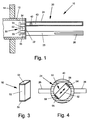
- the level sensor 10 shown in Fig. 1 for detection and / or monitoring the level in a container a tubular housing 12 which is in an opening of the container wall 14 at the level of the level to be monitored is attached.
- the end facing the inside of the container the housing 12 carries a mechanical vibration system 20.
- Das mechanical vibration system 20 is in the illustrated Example of a membrane 22 that is around its peripheral edge is connected to the edge of the tubular housing 12, and from two vibrating rods 24 and 25, each with one end are attached to the membrane 22 so that they are parallel to each other protrude from the membrane 22 into the interior of the container.
- each vibrating rod there are two diametrically opposite one another flat paddles 26 attached, extending from the free End of the vibrating rod over a part of its length extend and lie transverse to the plane that the axes of the contains two vibrating rods.
- these paddles is in 1 only one of the two paddles 26 of the vibrating rod 25 can be seen, while in Fig. 4 the two paddles 26 of the Vibrating rod 24 can be seen.
- the side of the membrane 22 facing away from the container is included an electromechanical transducer system 30 connected so is designed to be the mechanical vibration system 20 Can excite vibrations with its natural resonance frequency.
- the electromechanical transducer system contains 30 preferably an electromechanical excitation converter 31 and an electromechanical transducer 32.
- Each the two electromechanical transducers 31 and 32 is so trained that he a supplied alternating electrical signal (Alternating voltage or alternating current) into a mechanical Vibration and vice versa one acting on it mechanical vibration in an electrical alternating signal can convert.
- alternating electrical signal Alternating voltage or alternating current
- everyone Transducers 31 and 32 is a piezoelectric transducer that contains at least one piezoelectric element.
- a such a piezoelectric element is known to consist of a disk-shaped piezo crystal that lies between two Electrodes is arranged.
- the thickness of the piezo crystal changes depending on the on the electrodes generate applied voltage and vice versa mechanically forced changes in thickness of the piezo crystal an electrical voltage at the electrodes.
- the arousal converter 31 is connected to the membrane so that it due the thickness vibrations of his piezo crystal, which at Application of an electrical alternating voltage are generated, the diaphragm 22 vibrates on the two Vibrating rods 24 and 25 are transmitted so that these Vibrating rods counter to opposite mechanical vibrations run in their longitudinal direction, the plane of vibration the plane is the axis of the two vibrating bars contains and in Fig. 1 coincides with the plane of the drawing.
- the receiving transducer 32 is connected to the membrane 22 that he due to the mechanical vibration of the membrane 22nd an alternating electrical voltage between his two Electrodes generated.
- the piezoelectric transducers 31 and 32 are in a stack between membrane 22 and one Bridge 33 clamped by supports 34 and 35 in Distance from the membrane 22 is kept.
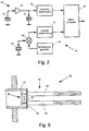
- the piezoelectric transducers 31 and 32 are in the in Fig. 2 shown way with a low frequency excitation and Evaluation circuit 36 connected in the housing 12th can be accommodated.
- One electrode each of each both transducers 31 and 32 are connected to a ground connection, for example through the membrane 22 and that Housing 12 can be formed.
- the other electrode of the Receive converter 32 is connected to the input of an amplifier 37 connected to the output of which the excitation converter 31 is connected is.
- the level sensor 10 lies with the two transducers 31 and 32, the mechanical vibration system 20 are coupled together in the feedback loop of the amplifier 37, which is designed so that the self-excitation is satisfied, so that the mechanical Vibration system via the two transducers 31 and 32 too Vibrations is excited with its natural resonance frequency.
- This natural resonance frequency is in the range of the audible acoustic frequencies, usually below 1000 Hz; it is a low frequency.
- the Natural resonance frequency of the mechanical vibration system 20 depends on whether the vibrating rods 24, 25 vibrate in air or immerse in a product.
- the natural resonance frequency is on the one hand due to the spring constant as the return spring acting membrane 22 and the other through the vibrating mass determined.
- the vibrating mass is there from the mass of the vibrating rods 24, 25 and from the mass of the taken from the vibrating rods during the oscillating movement surrounding medium. If the vibrating rods 24, 25 in Air, the entrained mass of air is negligible, and there is a natural resonance frequency one, essentially by the mass of the vibrating rods is determined. If, however, the vibrating rods 24, 25 in one If the product is immersed, the mass carried increases and accordingly, the natural resonance frequency of the mechanical Vibration system lower. This effect is through the paddles 26 reinforced because these paddles the carried Increase the mass of the product.
- a frequency discriminator 38 connected to the frequency of the Amplifier 37 output AC voltage, which is equal to Natural resonance frequency of the mechanical vibration system 20 is compared with a threshold. If this frequency is above the threshold, the output signal of Frequency discriminator 38 a first signal value indicating that the vibrating rods 24 and 25 swing in air and thus the level to be monitored has not been reached. If the frequency of the AC voltage emitted by the amplifier is below the threshold, the output signal the frequency discriminator 38 a second signal value, which indicates that the vibrating rods 24, 25 of the product are covered and thus the level to be monitored has been reached or exceeded.
- the structure and operation of the previously described low-frequency measuring system of the level sensor 20 are known for example from DE 33 36 991 A1.
- the in Fig. 1 level sensor differs of this prior art in that he also with a high-frequency measuring system.
- the sectional view of the vibrating rod 24 in FIG. 1 shows that this vibrating rod is designed as a hollow tube 40 is.
- the hollow tube 40 is on that facing away from the membrane 22 Closed end.
- an ultrasonic transducer 42 In the hollow tube 40 is close to the membrane 22 attached an ultrasonic transducer 42 so that it is high-frequency Transfer ultrasonic vibrations to the hollow tube can, which propagate as elastic waves in the hollow tube can use that as a waveguide for the elastic Serves waves.
- the elastic waves run along the Hollow tube 40 to the closed end at which it reflects and as echo waves to the ultrasonic transducer 42 return.
- the ultrasonic transducer 42 which acts as a transmitter transducer for transmission of elastic waves and as a receiving transducer for the reflected echo wave is used is preferably again a piezoelectric transducer that is suitable for high Frequencies is designed. 2 is also the excitation and Evaluation circuit 44 for the high-frequency measuring system of the Level sensor shown.
- a transmit pulse generator 45 generates short radio frequency pulses at periodic intervals, via a transceiver 46 to the ultrasonic transducer 42 are created, which are transmitted by each transmission pulse Transmission of an ultrasound pulse of the same frequency is excited.
- the one after each emission of an ultrasonic pulse received echo pulse is from the ultrasonic transducer 42 converted into an electrical receive pulse, the via the transceiver 46 of a transit time measurement circuit 47 is supplied.
- the transit time measuring circuit 47 determines the Duration between the transmission of a transmission pulse and the Arrival of the received pulse and it compares the measured Term with a threshold. If the measured Runtime is above the threshold, the output signal the transit time measuring circuit 47 a first signal value, which indicates that the hollow tube 40 is in air and thus the level to be monitored has not been reached. If in contrast, the measured transit time below the threshold the output signal of the transit time measuring circuit 47 a second signal value indicating that the hollow tube 40th is covered by the contents, and thus the one to be monitored Level is reached or exceeded.
- the duration of the ultrasonic pulses must be short compared to Term.
- the term in turn is because of the limited length of the vibrating rod 24 very short. Accordingly the frequency of the ultrasonic waves must be high; for example, it is on the order of 30 kHz.
- This utilization of the output signals of the two measuring systems can by a common signal processing circuit take place, for example, by a microcomputer 49 is formed.
- the vibrating rod 25 should be designed so that it is accurate the same vibration behavior as the vibrating rod 24 shows. So it is also a hollow tube with the same Dimensions like the hollow tube 40 of the vibrating rod 24, and at the point where the Ultrasonic transducer 42 is located in the vibrating rod 25 appropriate replacement mass attached.
- a further ultrasonic transducer in the vibrating rod 25 attach and with an associated excitation and evaluation circuit to connect, so that in addition to that low-frequency measuring system two high-frequency measuring systems available.
- the two high-frequency measuring systems can in this case be used for mutual control, which further increases the safety of the device becomes.
- FIG. 3 shows a perspective view of a piezoelectric Ultrasonic transducer 50, which is for use as Ultrasonic transducer 42 in the device of FIG. 1 is suitable and FIG. 4 shows a cross section through the ultrasound transducer 50 containing section of the hollow tube 40.
- the piezoelectric ultrasonic transducer 50 consists of a cuboidal piezo crystal 52, which is dimensioned so that it can be used in the hollow tube 40 and to each other diametrically opposite points on the wall of the hollow tube is present.
- Electrodes 54, 56 attached to which the electrical excitation pulses are applied be so that the piezo crystal 52 in diametrical directional thickness vibrations is offset, as in Fig. 4th is indicated by the double arrow. These vibrations are transferred to the wall of the hollow tube 40 and propagate in it as elastic waves.
- the piezoelectric transducer 50 can be in the hollow tube 40 be attached by gluing using an adhesive that the circular segment-shaped cavities 58 between the Electrodes 54, 56 and the inner surface of the wall of the hollow tube 40 fills and a rigid after curing Connection that gives the vibrations of the piezoelectric Converter 50 on the wall of the hollow tube 40th transmits.
- the piezo crystal 52 can also do so be shaped so that the electrodes 54, 56 carrying Surfaces have the same curvature as the inside surface of the wall of the hollow tube 40 and thus flat after installation of this inner surface. For example can be achieved in that the piezo crystal 52 from a circular disc is cut, its diameter is equal to the inside diameter of the hollow tube 40.
- the piezoelectric transducer 50 excites the tubular elastic waveguide formed by the hollow tube 40 to the oscillation mode shown in FIG. 5.
- the thickness vibrations of the piezo crystal 52 represented by the arrows F (t) cause the elliptical tube cross section Q 0 at a point in time t 0 , which after a half period at point in time t 1 results in an elliptical cross section Q 1 rotated by 90 ° and after a full period in Time t 2 passes into the elliptical cross section Q 2 rotated by 180 °, which again corresponds to the cross section Q 0 .
- This cross-sectional deformation propagates at the speed of propagation c of the ultrasonic waves along the tubular waveguide, so that the elliptical cross sections are rotated by 90 ° with respect to each other at half the wavelength ⁇ / 2.
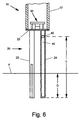
- the fill level sensor 10 can, as shown in FIG. 1 is horizontal at the level to be monitored be fixed in an opening of the container wall 14, it can but also, as shown in Fig. 6, in the vertical position be installed in the container.
- this enables high-frequency Measuring system in this case not only the finding whether the level to be monitored has been reached or not, but also the determination of the exact level, i.e. of the Height of the product surface F, in the area of the section L between the ultrasonic transducer 42 and the end of the through the vibrating rod 24 formed elastic waveguide.
- the ultrasonic waves generated by the ultrasonic transducer 42 propagate along the pipe wall at the speed of sound c determined by the material of the hollow pipe 40.
- the length D of the immersed section can be calculated from this become.
- the fill level sensor 60 has a tubular housing 62, which is at the level of the monitored Level is attached to a container wall 64, that it is complete or at least for the most part its length is inside the container.
- the low frequency Measuring system again contains a mechanical one Vibration system 70 with a membrane 72 that surrounds it Peripheral edge with the edge of the tubular housing 62 is connected, and with two oscillating rods 74, 75, the are each attached at one end to the membrane 72 and at their free ends two opposite each other Wear paddle 76.
- the vibrating rods 74, 75 are made in this embodiment made of flat metal plates.
- the in Inside of the housing side of the membrane 72 is with an electromechanical transducer system 78 connected so is designed to be the mechanical vibration system 70 Can excite vibrations with its natural resonance frequency.
- the converter system 78 is designed in the same way as the transducer system 30 of FIG. 1 and with an excitation and Evaluation circuit of the type shown in Fig. 2 connected.
- the low-frequency measuring system corresponds to the level sensor 60 of FIG. 7 the low-frequency measuring system of the level sensor 10 of Fig. 1, and it has the same Works like this.
- Fig. 8 shows a possible formation on one side of the piezo crystal Detect 82 attached electrodes 84.
- Electrodes 84a, 84b, 84c and 84d consist of four sectors 84a, 84b, 84c and 84d; the electrodes 84a diametrically opposite each other, 84c on the one hand and 84b, 84d on the other hand are each on the the same potential as the plus and minus signs is displayed.
- the one on the opposite side attached electrodes 86 are formed in the same way and wired.
- the piezo crystal is so radial polarized that under the influence of one to the Electrodes 84 and 86 applied an electrical voltage certain polarity to an elliptical cross section deformed, as exaggerated in Fig. 8, while he is applying an electrical voltage the opposite polarity to one rotated by 90 ° deformed elliptical cross section.
- Electrodes 84 and 86 are equipped with an excitation and evaluation circuit in Fig. 2 connected type, so that when creating of an electrical transmission pulse formed by the housing 62 tubular waveguide for ultrasonic vibrations of the vibration mode shown in FIG. 5 is excited. These ultrasonic vibrations plant themselves as elastic Ultrasonic waves in the housing wall up to that with the Membrane 72 connected end where they are reflected and as echo waves to the piezoelectric transducer 80 to return. By measuring the transit time of the ultrasonic pulses can be determined whether the housing 62 in Air or whether it is immersed in the contents.
- FIG. 9 Another embodiment of a level sensor 90 with a low-frequency measuring system and a high-frequency Measuring system is shown in Fig. 9.
- the fill level sensor 90 has, in the same way as the level sensors described above 10 and 60, a tubular housing 91 that carries a mechanical vibration system 92 that consists of a membrane 93 and two vibrating rods 94, 95 and one Transducer system 96 to vibrate at its natural resonant frequency is excited.
- the mechanical vibration system 92 forms in connection with an excitation and evaluation circuit the type shown in Fig. 2, the low-frequency measuring system.
- the level sensor 90 does not have an elastic one Waveguide for transmission of ultrasonic waves; much more the high-frequency measuring system is formed in that the area 97 between the oscillating rods 94 and 95 Membrane 92 is excited to vibrate at a frequency, which is much higher than the natural resonance frequency of the low frequency mechanical vibration system 92 and is preferred the natural resonance frequency of the membrane region 97 corresponds.
- This suggestion is preferably made by the same transducer system 96, which is also used to excite the natural resonance oscillation of the low-frequency mechanical vibration system 92 is used.
- the Monitoring of the fill level using the high-frequency measuring system does not take place in this case by a runtime measurement, but by evaluating the natural resonance frequency of the Membrane area 97, which if the membrane area of Is covered, is lower than if the Membrane region 97 vibrates in air.
Abstract
Description
Die Erfindung betrifft eine Vorrichtung zur Feststellung und/oder Überwachung des Füllstands eines Füllguts in einem Behälter mit Hilfe eines Füllstandssensors, der ein mechanisches Schwingsystem und ein elektromechanisches Wandlersystem aufweist, wobei der Füllstandssensor so am Behälter angebracht ist, daß das mechanische Schwingsystem mit dem Füllgut in Berührung kommt, wenn dieses einen vorbestimmten Füllstand erreicht, und wobei das Wandlersystem mit einer Niederfrequenz-Erregungsschaltung verbunden ist, die so ausgebildet ist, daß sie das mechanische Schwingsystem zu einer niederfrequenten Schwingung erregt, sowie mit einer Niederfrequenz-Auswerteschaltung, die durch Auswertung der Frequenz und/oder der Amplitude eines vom Wandlersystem gelieferten elektrischen Signals ein Ausgangssignal liefert, das anzeigt, ob das mechanische Schwingsystem mit dem Füllgut in Berührung steht oder nicht.The invention relates to a device for detection and / or monitoring the filling level of a filling material in one Container using a level sensor, which is a mechanical Vibration system and an electromechanical transducer system has, the level sensor so on the container is appropriate that the mechanical vibration system with the Filling material comes into contact when this has a predetermined Level reached, and the converter system with a Low frequency excitation circuit is connected, so is designed to the mechanical vibration system excited with a low frequency vibration, as well as with a Low-frequency evaluation circuit, which is evaluated by the Frequency and / or the amplitude of one from the transducer system delivered electrical signal provides an output signal, that indicates whether the mechanical vibration system with the Product is in contact or not.
Eine Vorrichtung dieser Art ist beispielsweise aus der DE 33 36 991 A1 bekannt. Bei dieser bekannten Vorrichtung besteht das mechanische Schwingsystem aus zwei Schwingstäben, die im Abstand nebeneinander an einer Membran befestigt sind, deren Rand mit einem Einschraubstück verbunden ist. Das elektromechanische Wandlersystem umfaßt einen Erregungswandler und einen Empfangswandler. Wenn an den Erregungswandler eine Wechselspannung angelegt wird, wirkt er auf die den Schwingstäben abgewandte Seite der Membran so ein, daß die Schwingstäbe in gegensinnige Schwingungen quer zu ihrer Längsrichtung versetzt werden, und der Empfangswandler setzt die Schwingungen des mechanischen Schwingsystems in eine elektrische Wechselspannung um. Die beiden Wandler sind mit einem Verstärker in einem Selbsterregungskreis verbunden, so daß sich das mechanische Schwingsystem zu Schwingungen mit seiner Eigenresonanzfrequenz erregt. Die Eigenresonanzfrequenz des mechanischen Schwingsystems hängt davon ab, ob die Schwingstäbe in Luft schwingen oder in das Füllgut im Behälter eintauchen; sie ist im eingetauchten Zustand niedriger als beim Schwingen in Luft, liegt aber in allen Fällen im Niederfrequenzbereich unter 1000 Hz. Die Niederfrequenz-Auswerteschaltung vergleicht die Frequenz der im Selbsterregungskreis bestehenden elektrischen Wechselspannung, die mit der Eigenresonanzfrequenz des mechanischen Schwingsystems übereinstimmt, mit einem Schwellenwert, und sie gibt ein Ausgangssignal ab, das anzeigt, ob diese Frequenz über oder unter dem Schwellenwert liegt.A device of this type is for example from the DE 33 36 991 A1 known. In this known device the mechanical vibration system consists of two vibration bars, which are attached next to each other on a membrane are, the edge of which is connected with a screw-in piece is. The electromechanical transducer system includes an excitation transducer and a receive converter. When to the arousal converter an AC voltage is applied, it acts on the side of the membrane facing away from the vibrating rods one that the vibrating rods transversely in opposite vibrations are displaced to their longitudinal direction, and the receiving transducer sets the vibrations of the mechanical vibration system into an electrical alternating voltage. The two Transducers are in a self-excitation circuit with an amplifier connected so that the mechanical vibration system excited to vibrate at its natural resonance frequency. The Natural resonance frequency of the mechanical vibration system depends depends on whether the vibrating rods vibrate in air or in that Immerse the contents in the container; she is immersed in the State lower than when swinging in air, but lies in all cases in the low frequency range below 1000 Hz Low frequency evaluation circuit compares the frequency of the electrical AC voltage existing in the self-excitation circuit, with the natural resonance frequency of the mechanical Vibration system matches, with a threshold, and it emits an output signal which indicates whether this Frequency is above or below the threshold.
Eine aus der DE 32 15 040 C2 bekannte Vorrichtung zur
Feststellung und/oder Überwachung des Füllstands in einem
Behälter hat ein mechanisches Schwingsystem, das durch einen
rohrförmigen Hohlkörper gebildet ist, in dessen Hohlraum ein
Querglied angeordnet ist, das an zwei einander gegenüberliegenden
Befestigungspunkten an der Innenwand des Hohlraumes
befestigt ist. Das Wandlersystem, das einen Erregungswandler
und einen Empfangswandler enthält, wirkt mit dem Querglied
zusammen, das in radiale Schwingungen versetzbar ist, die
auf die Wand des rohrförmigen Hohlkörpers übertragen werden.
Die Eigenresonanzfrequenz dieses mechanischen Schwingsystems
liegt zwischen 20 und 30 kHz. Die Schwingung der Außenwand
des zylindrischen Hohlkörpers wird bei Berührung mit dem
Füllgut gedämpft, und dementsprechend ändert sich die Amplitude
der vom Empfangswandler abgegebenen Wechselspannung.
Die Auswerteschaltung vergleicht die Amplitude dieser Wechselspannung
mit einem Schwellenwert, um anzuzeigen, ob der
rohrförmige Hohlkörper mit dem Füllgut in Berührung steht
oder nicht.A device known from
Es sind andererseits Vorrichtungen zur Feststellung und/oder Überwachung des Füllstands in einem Behälter bekannt, die kein mit seiner Eigenresonanzfrequenz schwingendes mechanisches Schwingsystem enthalten, sondern die Anwesenheit eines Füllguts bei einem vorbestimmten Füllstand mit Hilfe von elastischen Wellen feststellen, deren Frequenz im Bereich der Ultraschallfrequenzen liegt. So beschreibt die EP 0 409 732 B1 bzw. die entsprechende DE 690 08 955 T2 einen Detektor zur Anzeige einer Flüssigkeit mit einem vertikal angeordneten Wellenleiter für elastische Wellen, dessen unteres Ende auf der Höhe des zu überwachenden Füllstands liegt. Der Wellenleiter hat zwei zylindrische Bereiche, von denen der obere Bereich vollzylindrisch ist und der untere Bereich, der einen größeren Außendurchmesser als der obere Bereich hat, vollzylindrisch oder rohrförmig sein kann. Ein am oberen Ende des Wellenleiters angebrachter Wandler sendet impulsförmige elastische Wellen aus, die durch den Wellenleiter zum unteren Ende laufen. Die Frequenz der elastischen Wellen liegt in der Größenordnung von 75 bis 125 kHz. Wenn das untere Ende des Wellenleiters nicht in Kontakt mit der Flüssigkeit steht, wird der ausgesandte Wellenzug am Ende des Wellenleiters reflektiert, so daß er als Echo großer Amplitude zu dem Wandler zurückläuft und von diesem in ein elektrisches Empfangssignal mit entsprechend großer Amplitude umgewandelt wird. Wenn dagegen das untere Ende des Wellenleiters in die Flüssigkeit eintaucht, wird der vom Wandler ausgesandte Wellenzug von der Flüssigkeit absorbiert, was zu einer beträchtlichen Abschwächung des reflektierten Echos führt. Durch Vergleich der Amplituden des elektrischen Empfangssignals mit einem Schwellenwert kann daher festgestellt werden, ob der Füllstand der Flüssigkeit im Behälter über oder unter der Höhe des unteren Endes des Wellenleiters steht. Da die Dämpfung der reflektierten Echos umso größer ist, je weiter der Wellenleiter in die Flüssigkeit eintaucht, kann durch Vergleich der Amplitude des elektrischen Empfangssignals mit verschiedenen Schwellenwerten auch festgestellt werden, auf welcher Höhe der Füllstand innerhalb eines gewissen Abschnitts des unteren Bereichs des Wellenleiters liegt.On the other hand, there are devices for detection and / or Monitoring the level in a container is known no mechanical vibrating with its natural resonance frequency Vibration system included, but the presence a filling material at a predetermined filling level with the help of elastic waves, their frequency in the Range of ultrasound frequencies is. So describes the EP 0 409 732 B1 and the corresponding DE 690 08 955 T2 a detector for displaying a liquid with a vertically arranged waveguide for elastic waves, the lower end of which is at the level to be monitored Level. The waveguide has two cylindrical ones Areas of which the upper area is fully cylindrical and the lower section, which has a larger outer diameter than the upper area has, fully cylindrical or tubular can be. One attached to the top of the waveguide Transducer sends out pulsed elastic waves that run through the waveguide to the lower end. The frequency the elastic waves are in the order of 75 to 125 kHz. If the lower end of the waveguide is not in Is in contact with the liquid, the emitted Wave train reflected at the end of the waveguide so that it returns to the transducer as a large amplitude echo and from this into an electrical reception signal with accordingly large amplitude is converted. If, however, the lower one End of the waveguide is immersed in the liquid the wave train emitted by the transducer from the liquid absorbed, which leads to a considerable weakening of the reflected echoes. By comparing the amplitudes the received electrical signal with a threshold can therefore be determined whether the level of the Liquid in the container above or below the level of the bottom End of the waveguide is. Because the attenuation of the reflected Echoes are greater the further the waveguide is in the liquid can be immersed by comparing the amplitude of the electrical received signal with different Thresholds are also established at what level the level within a certain section of the lower region of the waveguide.
Auf dem Markt gibt es somit niederfrequente und hochfrequente Systeme zur Feststellung und/oder Überwachung des Füllstands in einem Behälter mittels mechanischer Schwingungen. Typische Frequenzen der niederfrequenten Meßsysteme liegen im hörbaren Schallbereich unterhalb von 1000 Hz, während typische Frequenzen der hochfrequenten Meßsysteme im Ultraschallbereich oberhalb von 15 kHz liegen.There are thus low-frequency and high-frequency on the market Systems for determining and / or monitoring the level in a container by means of mechanical vibrations. Typical frequencies of the low-frequency measuring systems are in the audible sound range below 1000 Hz, while typical frequencies of the high-frequency measuring systems in the ultrasonic range are above 15 kHz.
Jedes dieser Prinzipien hat Vor- und Nachteile, je nach dem zu erfassenden Füllgut und den vorherrschenden Umgebungseinflüssen. Beispielsweise haben hochfrequente Meßsysteme Probleme bei ausgasenden Füllgütern, wie Sprudel, da Blasen an dem mechanischen Schwingsystem zu einer starken Verschmierung des Meßsignals führen. Dieses Problem kann nur durch eine aufwendige Auswertung von Mehrfachreflexionen bewältigt werden. Niederfrequente Meßsysteme arbeiten dagegen bei ausgasenden Füllgütern problemlos. Unterschiedlich ist auch das Vehalten im Falle einer Ansatzbildung. Bei weichem Ansatz arbeiten niederfrequente Meßsysteme unzuverlässig, hochfrequente Meßsysteme dagegen zuverlässig, während bei hartem Ansatz das Verhalten umgekehrt ist.Each of these principles has advantages and disadvantages, depending on the medium to be recorded and the prevailing environmental influences. For example, high-frequency measuring systems have problems with outgassing fillings, like sparkling water, because bubbles are on the mechanical vibration system for heavy smearing of the measurement signal. This problem can only be solved by coped with a complex evaluation of multiple reflections become. In contrast, low-frequency measuring systems work outgassing products without problems. It is also different driving in the event of a build-up. With soft Approach, low-frequency measuring systems work unreliably, high-frequency measuring systems, on the other hand, reliable, while at hard approach the behavior is reversed.
Schließlich werden niederfrequente Meßsysteme durch niederfrequente Fremdvibrationen und hochfrequente Meßsysteme durch hochfrequente Fremdvibrationen gestört, während beide Arten von Meßsystemen jeweils durch Fremdvibrationen des anderen Frequenzbereichs nicht beeinträchtigt werden. Finally, low-frequency measuring systems are replaced by low-frequency External vibrations and high-frequency measuring systems disturbed by high frequency external vibrations while both Types of measuring systems each due to external vibrations of the other frequency range are not affected.
Aufgabe der Erfindung ist es, eine kostengünstige Vorrichtung zur Feststellung und/oder Überwachung des Füllstands in einem Behälter zu schaffen, die vielseitig zur Erfassung des Füllstands unterschiedlicher Füllgüter unter verschiedenen Bedingungen einsetzbar ist.The object of the invention is an inexpensive device to determine and / or monitor the level in to create a container that is versatile for capturing the Fill levels of different products under different Conditions can be used.
Ausgehend von einer Vorrichtung der eingangs angegebenen Art wird diese Aufgabe nach der Erfindung dadurch gelöst, daß ein Bestandteil des Füllstandssensors, der mit dem Füllgut in Berührung kommt, wenn dieses den vorbestimmten Füllstand erreicht, mit einem elektromechanischen Wandlersystem zur Anregung einer hochfrequenten elastischen Schwingung in dem Bestandteil verbunden ist, und daß eine Hochfrequenz-Auswerteschaltung vorgesehen ist, die durch Auswertung eines in Abhängigkeit von der hochfrequenten elastischen Schwingung erzeugten elektrischen Signals ein Ausgangssignal erzeugt, das anzeigt, ob der Bestandteil mit dem Füllgut in Berührung steht oder nicht.Starting from a device of the type specified at the outset This object is achieved according to the invention in that a component of the level sensor that with the product comes into contact when it reaches the predetermined level achieved with an electromechanical transducer system Excitation of a high-frequency elastic vibration in the Component is connected, and that a high-frequency evaluation circuit is provided, which by evaluating an in Dependence on the high-frequency elastic vibration generated electrical signal generates an output signal, this indicates whether the component is in contact with the product stands or not.
Die erfindungsgemäße Vorrichtung besteht aus der Vereinigung eines niederfrequenten Meßsystems mit einem hochfrequenten Meßsystem, wobei für das hochfrequente Meßsystem ein Bestandteil des niederfrequenten Meßsystems verwendet wird. Diese Lösung ist einfach und kostensparend, und sie ergibt insbesondere den Vorteil, daß die Einbaubedingungen für das kombinierte System die gleichen sind wie für das niederfrequente System allein. Somit kann das kombinierte System einfach durch Austausch gegen ein vorhandenes niederfrequentes System eingebaut werden, ohne daß hierzu Änderungen am Behälter erforderlich sind. Da praktisch für jeden Anwendungsfall wenigstens eines der beiden Meßsysteme ein brauchbares Ergebnis liefert, kann mit dem kombinierten System der Füllstand in einem breiten Spektrum von Füllgütern und Anwendungsbedingungen festgestellt oder überwacht werden. In den Fällen, in denen beide Meßsysteme brauchbare Ergebnisse liefern, besteht eine Redundanz, die eine erhöhte Sicherheit ergibt und eine wechselseitige Kontrolle der Funktion der beiden Meßsysteme ermöglicht. The device according to the invention consists of the union of a low-frequency measuring system with a high-frequency Measuring system, a component for the high-frequency measuring system of the low-frequency measuring system is used. This solution is simple and economical, and it results in particular the advantage that the installation conditions for the combined system are the same as for the low frequency System alone. Thus the combined system simply by exchanging for an existing low-frequency one System can be installed without changes to the Containers are required. Since practically for every application at least one of the two measuring systems is a usable one The combined system of Level in a wide range of products and Conditions of use are determined or monitored. In the cases where both measurement systems have useful results deliver, there is redundancy, which increases security results and a mutual control of the function of the enables two measuring systems.
Eine Ausführungsform der erfindungsgemäßen Vorrichtung besteht darin, daß der für das hochfrequente Meßsystem verwendete Bestandteil des Füllstandssensors als elastischer Wellenleiter ausgebildet ist, in dem sich die hochfrequente elastische Schwingung als Welle fortpflanzt, und daß die Hochfrequenz-Auswerteschaltung die Laufzeit der elastischen Welle erfaßt und auswertet.An embodiment of the device according to the invention exists in that used for the high-frequency measuring system Part of the level sensor as elastic Waveguide is formed in which the high frequency propagates elastic vibration as a wave, and that the High-frequency evaluation circuit the runtime of the elastic Wave recorded and evaluated.
Eine andere Ausführungsform der erfindungsgemäßen Vorrichtung besteht darin, daß die Hochfrequenz-Auswerteschaltung die Frequenz der hochfrequenten elastischen Schwingung des Bestandteils auswertet.Another embodiment of the device according to the invention is that the high-frequency evaluation circuit the frequency of the high frequency elastic vibration of the Evaluates component.
Vorteilhafte Ausgestaltungen und Weiterbildungen der Erfindung sind in den Unteransprüchen gekennzeichnet.Advantageous refinements and developments of Invention are characterized in the subclaims.
Weitere Merkmale und Vorteile der Erfindung ergeben sich aus der folgenden Beschreibung von Ausführungsbeispielen, die in der Zeichnung dargestellt sind. In der Zeichnung zeigen:
- Fig. 1
- eine Schnittansicht einer Vorrichtung zur Feststellung und/oder Überwachung des Füllstands in einem Behälter gemäß einer ersten Ausführungsform der Erfindung,
- Fig. 2
- das Schaltbild der Erregungs- und Auswerteschaltungen für die Vorrichtung von Fig. 1,
- Fig. 3
- eine perspektivische Ansicht des in der Vorrichtung von Fig. 1 verwendeten Ultraschallwandlers,
- Fig. 4
- eine Querschnittansicht des den Ultraschallwandler enthaltenden Schwingstabs der Vorrichtung von Fig. 1,
- Fig. 5
- eine schematische Darstellung einer bei der Vorrichtung von Fig. 1 angewendeten elastischen Schwingung,
- Fig. 6
- eine andere Anwendung der Vorrichtung von Fig. 1,
- Fig. 7
- eine zweite Ausführungsform der erfindungsgemäßen Vorrichtung,
- Fig. 8
- einen bei der Vorrichtung von Fig. 7 angewendeten piezoelektrischen Wandler und
- Fig. 9
- eine dritte Ausführungsform der erfindungsgemäßen Vorrichtung.
- Fig. 1
- 2 shows a sectional view of a device for determining and / or monitoring the fill level in a container according to a first embodiment of the invention,
- Fig. 2
- the circuit diagram of the excitation and evaluation circuits for the device of Fig. 1,
- Fig. 3
- 2 shows a perspective view of the ultrasonic transducer used in the device of FIG. 1,
- Fig. 4
- 2 shows a cross-sectional view of the vibrating rod of the device from FIG. 1 containing the ultrasonic transducer,
- Fig. 5
- 1 shows a schematic illustration of an elastic oscillation used in the device of FIG. 1,
- Fig. 6
- another application of the device of Fig. 1,
- Fig. 7
- a second embodiment of the device according to the invention,
- Fig. 8
- a piezoelectric transducer used in the device of FIG. 7 and
- Fig. 9
- a third embodiment of the device according to the invention.
Der in Fig. 1 gezeigte Füllstandssensor 10 zur Feststellung
und/oder Überwachung des Füllstands in einem Behälter hat
ein rohrförmiges Gehäuse 12, das in einer Öffnung der Behälterwand
14 auf der Höhe des zu überwachenden Füllstands
befestigt ist. Das dem Inneren des Behälters zugewandte Ende
des Gehäuses 12 trägt ein mechanisches Schwingsystem 20. Das
mechanische Schwingsystem 20 besteht bei dem dargestellten
Beispiel aus einer Membran 22, die rings um ihren Umfangsrand
mit dem Rand des rohrförmigen Gehäuses 12 verbunden ist, und
aus Zwei Schwingstäben 24 und 25, die jeweils mit einem Ende
an der Membran 22 befestigt sind, so daß sie parallel zueinander
von der Membran 22 in das Innere des Behälters ragen.
An jedem Schwingstab sind zwei einander diametral gegenüberliegende
flache Paddel 26 angebracht, die sich vom freien
Ende des Schwingstabes über einen Teil von dessen Länge
erstrecken und quer zu der Ebene liegen, die die Achsen der
beiden Schwingstäbe enthält. Von diesen Paddeln ist in
Fig. 1 nur eines der beiden Paddel 26 des Schwingstabes 25
zu sehen, während in Fig. 4 die beiden Paddel 26 des
Schwingstabes 24 zu erkennen sind.The
Die dem Behälter abgewandte Seite der Membran 22 ist mit
einem elektromechanischen Wandlersystem 30 verbunden, das so
ausgebildet ist, daß es das mechanische Schwingsystem 20 zu
Schwingungen mit seiner Eigenresonanzfrequenz anregen kann.
Zu diesem Zweck enthält das elektromechanische Wandlersystem
30 vorzugsweise einen elektromechanischen Erregungswandler
31 und einen elektromechanischen Empfangswandler 32. Jeder
der beiden elektromechanischen Wandler 31 und 32 ist so
ausgebildet, daß er ein zugeführtes elektrisches Wechselsignal
(Wechselspannung oder Wechselstrom) in eine mechanische
Schwingung und umgekehrt eine auf ihn einwirkende
mechanische Schwingung in ein elektrisches Wechselsignal
umwandeln kann. Als Beispiel ist angenommen, daß jeder
Wandler 31 und 32 ein piezoelektrischer Wandler ist, der
wenigstens ein piezoelektrisches Element enthält. Ein
solches piezoelektrisches Element besteht bekanntlich aus
einem scheibenförmigen Piezokristall, der zwischen zwei
Elektroden angeordnet ist. Die Dicke des Piezokristalls
ändert sich in Abhängigkeit von der an die Elektroden
angelegten elektrischen Spannung und umgekehrt erzeugen
mechanisch erzwungene Dickenänderungen des Piezokristalls
eine elektrische Spannung an den Elektroden. Der Erregungswandler
31 ist so mit der Membran verbunden, daß er aufgrund
der Dickenschwingungen seines Piezokristalls, die beim
Anlegen einer elektrischen Wechselspannung erzeugt werden,
die Membran 22 in Schwingungen versetzt, die auf die beiden
Schwingstäbe 24 und 25 übertragen werden, so daß diese
Schwingstäbe gegensinnige mechanische Schwingungen quer zu
ihrer Längsrichtung ausführen, wobei die Schwingungsebene
die Ebene ist, die die Achsen der beiden Schwingstäbe
enthält und in Fig. 1 mit der Zeichenebene zusammenfällt.
Der Empfangswandler 32 ist so mit der Membran 22 verbunden,
daß er aufgrund der mechanischen Schwingung der Membran 22
eine elektrische Wechselspannung zwischen seinen beiden
Elektroden erzeugt. Die piezoelektrischen Wandler 31 und 32
sind in einem Stapel zwischen der Membran 22 und einer
Brücke 33 eingespannt, die durch Stützen 34 und 35 im
Abstand von der Membran 22 gehalten ist.The side of the
Die piezoelektrischen Wandler 31 und 32 sind in der in
Fig. 2 gezeigten Weise mit einer Niederfrequenz-Erregungs- und
Auswerteschaltung 36 verbunden, die in dem Gehäuse 12
untergebracht sein kann. Jeweils eine Elektrode jedes der
beiden Wandler 31 und 32 ist mit einem Masseanschluß verbunden,
der beispielsweise durch die Membran 22 und das
Gehäuse 12 gebildet sein kann. Die andere Elektrode des
Empfangswandlers 32 ist mit dem Eingang eines Verstärkers 37
verbunden, an dessen Ausgang der Erregungswandler 31 angeschlossen
ist. Somit liegt der Füllstandssensor 10 mit den
beiden Wandlern 31 und 32, die über das mechanische Schwingsystem
20 miteinander gekoppelt sind, im Rückkopplungskreis
des Verstärkers 37, der so ausgebildet ist, daß die Selbsterregungsbedingng
erfüllt ist, so daß das mechanische
Schwingsystem über die beiden Wandler 31 und 32 zu
Schwingungen mit seiner Eigenresonanzfrequenz angeregt wird.
Diese Eigenresonanzfrequenz liegt im Bereich der hörbaren
akustischen Frequenzen, in der Regel unter 1000 Hz; es
handelt sich also um eine Niederfrequenz.The
Zur Überwachung des Füllstands mit dem bisher beschriebenen
Füllstandssensor 10 wird die Tatsache ausgenutzt, daß die
Eigenresonanzfrequenz des mechanischen Schwingsystems 20
davon abhängt, ob die Schwingstäbe 24, 25 in Luft schwingen
oder in ein Füllgut eintauchen. Die Eigenresonanzfrequenz
ist einerseits durch die Federkonstante der als Rückholfeder
wirkenden Membran 22 und andererseits durch die
schwingende Masse bestimmt. Die schwingende Masse besteht
aus der Masse der Schwingstäbe 24, 25 und aus der Masse des
von den Schwingstäben bei der Schwingbewegung mitgenommenen
umgebenden Mediums. Wenn sich die Schwingstäbe 24, 25 in
Luft befinden, ist die mitgeführte Masse der Luft vernachlässigbar,
und es stellt sich eine Eigenresonanzfrequenz
ein, die im wesentlichen durch die Masse der Schwingstäbe
bestimmt ist. Wenn dagegen die Schwingstäbe 24, 25 in ein
Füllgut eintauchen, wird die mitgeführte Masse größer, und
dementsprechend wird die Eigenresonanzfrequenz des mechanischen
Schwingsystems niedriger. Diese Wirkung wird durch
die Paddel 26 verstärkt, da diese Paddel die mitgeführte
Masse des Füllguts vergrößern.To monitor the level with the previously described
Zur Erfassung der Änderung der Eigenresonanzfrequenz des
mechanischen Schwingsystems 20 ist in der Schaltung von
Fig. 2 an den Ausgang des Verstärkers 37 ein Frequenzdiskriminator
38 angeschlossen, der die Frequenz der vom
Verstärker 37 abgegebenen Wechselspannung, die gleich der
Eigenresonanzfrequenz des mechanischen Schwingsystems 20
ist, mit einem Schwellenwert vergleicht. Wenn diese Frequenz
über dem Schwellenwert liegt, hat das Ausgangssignal des
Frequenzdiskriminators 38 einen ersten Signalwert, der anzeigt,
daß die Schwingstäbe 24 und 25 in Luft schwingen und
somit der zu überwachende Füllstand nicht erreicht ist. Wenn
dagegen die Frequenz der vom Verstärker abgegebenen Wechselspannung
unter dem Schwellenwert liegt, hat das Ausgangssignal
des Frequenzdiskriminators 38 einen zweiten Signalwert,
der anzeigt, daß die Schwingstäbe 24, 25 von dem Füllgut
bedeckt sind und somit der zu überwachende Füllstand
erreicht oder überschritten ist.To detect the change in the natural resonance frequency of the
Der Aufbau und die Funktionsweise des bisher beschriebenen
niederfrequenten Meßsystems des Füllstandssensors 20 sind
beispielsweise aus der DE 33 36 991 A1 bekannt. Der in
Fig. 1 dargestellte Füllstandssensor unterscheidet sich aber
von diesem Stand der Technik dadurch, daß er zusätzlich mit
einem hochfrequenten Meßsystem ausgestattet ist.The structure and operation of the previously described
low-frequency measuring system of the
Die Schnittansicht des Schwingstabes 24 in Fig. 1 läßt erkennen,
daß dieser Schwingstab als Hohlrohr 40 ausgebildet
ist. Das Hohlrohr 40 ist an dem der Membran 22 abgewandten
Ende verschlossen. In dem Hohlrohr 40 ist nahe der Membran
22 ein Ultraschallwandler 42 so angebracht, daß er hochfrequente
Ultraschallschwingungen auf das Hohlrohr übertragen
kann, die sich als elastische Wellen in dem Hohlrohr fortpflanzen
können, das als Wellenleiter für die elastischen
Wellen dient. Die elastischen Wellen laufen entlang dem
Hohlrohr 40 zu dem verschlossenen Ende, an dem sie reflektiert
werden und als Echowellen zu dem Ultraschallwandler
42 zurückkehren. Zur Überwachung des Füllstands mit diesem
hochfrequenten Meßsystem wird die Tatsache ausgenutzt, daß
die Ausbreitungsgeschwindigkeit der Ultraschallwellen in dem
Hohlrohr 40 davon abhängt, ob sich das Hohlrohr 40 in Luft
befindet oder in ein Füllgut eingetaucht ist; sie ist bei
eingetauchtem Hohlrohr wegen der zusätzlichen Masse, die mit
der Rohrwand in Verbindung steht, niedriger als in Luft, und
demzufolge ist die Laufzeit der elastischen Wellen bei eingetauchtem
Hohlrohr größer als dann, wenn sich das Hohlrohr
in Luft befindet.The sectional view of the vibrating
Der Ultraschallwandler 42, der als Sendewandler für die Aussendung
der elastischen Wellen und als Empfangswandler für
die reflektierten Echowellen dient, ist vorzugsweise wieder
ein piezoelektrischer Wandler, der für entsprechend hohe
Frequenzen ausgelegt ist. In Fig. 2 ist auch die Erregungs- und
Auswerteschaltung 44 für das hochfrequente Meßsystem des
Füllstandssensors dargestellt. Ein Sendeimpulsgenerator 45
erzeugt in periodischen Abständen kurze Hochfrequenzimpulse,
die über eine Sende-Empfangsweiche 46 an den Ultraschallwandler
42 angelegt werden, der durch jeden Sendeimpuls zur
Aussendung eines Ultraschallimpulses der gleichen Frequenz
angeregt wird. Der nach jeder Aussendung eines Ultraschallimpulses
empfangene Echoimpuls wird vom Ultraschallwandler
42 in einen elektrischen Empfangsimpuls umgewandelt, der
über die Sende-Empfangsweiche 46 einer Laufzeitmeßschaltung
47 zugeführt wird. Die Laufzeitmeßschaltung 47 ermittelt die
Laufzeit zwischen der Aussendung eines Sendeimpulses und dem
Eintreffen des Empfangsimpulses, und sie vergleicht die gemessene
Laufzeit mit einem Schwellenwert. Wenn die gemessene
Laufzeit über dem Schwellenwert liegt, hat das Ausgangssignal
der Laufzeitmeßschaltung 47 einen ersten Signalwert,
der anzeigt, daß sich das Hohlrohr 40 in Luft befindet und
somit der zu überwachende Füllstand nicht erreicht ist. Wenn
dagegen die gemessene Laufzeit unter dem Schwellenwert
liegt, hat das Ausgangssignal der Laufzeitmeßschaltung 47
einen zweiten Signalwert, der anzeigt, daß das Hohlrohr 40
von dem Füllgut bedeckt ist, und somit der zu überwachende
Füllstand erreicht oder überschritten ist.The
Damit eine eindeutige Bestimmung der Laufzeit möglich ist,
muß die Dauer der Ultraschallimpulse kurz im Vergleich zur
Laufzeit sein. Die Laufzeit ihrerseits ist wegen der
begrenzten Länge des Schwingstabs 24 sehr kurz. Dementsprechend
muß die Frequenz der Ultraschallwellen hoch sein;
sie liegt beispielsweise in der Größenordnung von 30 kHz.So that the runtime can be clearly determined,
the duration of the ultrasonic pulses must be short compared to
Term. The term in turn is because of the
limited length of the vibrating
Man erhält auf diese Weise an den Ausgängen des Frequenzdiskriminators 38 und der Laufzeitmeßschaltung 47 zwei Füllstandsanzeigesignale, die unabhängig voneinander unter sehr verschiedenen Bedingungen entstehen, nämlich einerseits ein Signal, das von der vom Füllgut beeinflußten niedrigen Eigenresonanzfrequenz eines mechanischen Schwingsystems abhängt, und andererseits ein Signal, das von der vom Füllgut beeinflußten Ausbreitungsgeschwindigkeit bzw. Laufzeit hochfrequenter elastischer Wellen abhängt. Dadurch bieten sich dem Anwender die folgenden Möglichkeiten zur Verwertung dieser Signale:
- Wenn das zu überwachende Füllgut von solcher Beschaffenheit ist, daß die beiden Meßsysteme gültige Ergebnisse liefern, können die beiden Signale zur gegenseitigen Kontrolle und zur Erhöhung der Sicherheit der Meßanordnung verwendet werden. In diesem Fall ist die Messung mit Sicherheit gültig, wenn beide Signale den gleichen Zustand anzeigen. Wenn dagegen die beiden Signale unterschiedliche Zustände anzeigen, läßt sich gegebenenfalls feststellen, welches der beiden Meßsysteme ausgefallen ist, so daß die Messung mit dem anderen Meßsystem fortgesetzt werden kann.
- Wenn das zu überwachende Füllgut von solcher Beschaffenheit ist, daß nur eines der beiden Meßsysteme für die Überwachung geeignet ist, kann die Überwachung mit diesem Meßsystem durchgeführt werden, während das andere Meßsystem abgeschaltet ist. So kann beispielsweise die Überwachung des Füllstands von ausgasenden Füllgütern mit dem niederfrequenten Meßsystem und die Überwachung von Füllgütern, die zu weichem Ansatz neigen, mit dem hochfrequenten Meßsystem erfolgen. Beim Bestehen von Fremdvibrationen kann jeweils das Meßsystem verwendet werden, das für die Frequenz der Fremdvibrationen nicht empfindlich ist, also bei hochfrequenten Fremdvibrationen das niederfrequente Meßsystem und bei niederfrequenten Fremdvibrationen das hochfrequente Meßsystem.
- If the product to be monitored is of such a nature that the two measuring systems deliver valid results, the two signals can be used for mutual control and for increasing the security of the measuring arrangement. In this case the measurement is definitely valid if both signals indicate the same state. If, on the other hand, the two signals indicate different states, it may be possible to determine which of the two measuring systems has failed, so that the measurement can be continued with the other measuring system.
- If the product to be monitored is of such a nature that only one of the two measuring systems is suitable for monitoring, the monitoring can be carried out with this measuring system while the other measuring system is switched off. For example, the filling level of outgassing filling goods can be monitored using the low-frequency measuring system and the monitoring of filling goods which tend to be soft approach using the high-frequency measuring system. If there are external vibrations, the measuring system can be used which is not sensitive to the frequency of the external vibrations, i.e. the low-frequency measuring system for high-frequency external vibrations and the high-frequency measuring system for low-frequency external vibrations.
Diese Verwertung der Ausgangssignale der beiden Meßsysteme
kann durch eine gemeinsame Signalverarbeitungsschaltung
erfolgen, die beispielsweise durch einen Mikrocomputer 49
gebildet ist.This utilization of the output signals of the two measuring systems
can by a common signal processing circuit
take place, for example, by a
Natürlich muß bei der in Fig. 1 dargestellten Ausführungsform
der Schwingstab 25 so ausgebildet sein, daß er genau
das gleiche Schwingungsverhalten wie der Schwingstab 24
zeigt. Er ist also ebenfalls als Hohlrohr mit den gleichen
Abmessungen wie das Hohlrohr 40 des Schwingstabes 24 ausgebildet,
und an der Stelle, an der sich im Hohlrohr 40 der
Ultraschallwandler 42 befindet, ist im Schwingstab 25 eine
entsprechende Ersatzmasse angebracht. Wahlweise ist es auch
möglich, im Schwingstab 25 einen weiteren Ultraschallwandler
anzubringen und mit einer zugehörigen Erregungs- und Auswerteschaltung
zu verbinden, so daß zusätzlich zu dem
niederfrequenten Meßsystem zwei hochfrequente Meßsysteme
vorhanden sind. Die beiden hochfrequenten Meßsysteme können
in diesem Fall zur gegenseitigen Kontrolle verwendet werden,
wodurch die Sicherheit der Vorrichtung noch weiter erhöht
wird.Of course, in the embodiment shown in Fig. 1
the vibrating
Fig. 3 zeigt in perspektivischer Darstellung einen piezoelektrischen
Ultraschallwandler 50, der zur Verwendung als
Ultraschallwandler 42 in der Vorrichtung von Fig. 1 geeignet
ist, und Fig. 4 zeigt einen Querschnitt durch den den Ultraschallwandler
50 enthaltenden Abschnitt des Hohlrohres 40.
Der piezoelektrische Ultraschallwandler 50 besteht aus einem
quaderförmigen Piezokristall 52, der so bemessen ist, daß er
in das Hohlrohr 40 eingesetzt werden kann und an einander
diametral gegenüberliegenden Stellen an der Wand des Hohlrohres
anliegt. Auf den der Wand des Hohlrohres zugewandten
Schmalseiten des Piezokristalls 52 sind Elektroden 54, 56
angebracht, an die die elektrischen Erregungsimpulse angelegt
werden, so daß der Piezokristall 52 in diametral
gerichtete Dickenschwingungen versetzt wird, wie in Fig. 4
durch den Doppelpfeil angedeutet ist. Diese Schwingungen
werden auf die Wand des Hohlrohres 40 übertragen und
pflanzen sich darin als elastische Wellen fort.Fig. 3 shows a perspective view of a piezoelectric
Der piezoelektrische Wandler 50 kann in dem Hohlrohr 40
durch Kleben befestigt werden, wobei ein Klebstoff verwendet
wird, der die kreissegmentförmigen Hohlräume 58 zwischen den
Elektroden 54, 56 und der Innenfläche der Wand des Hohlrohres
40 ausfüllt und nach dem Aushärten eine starre
Verbindung ergibt, die die Schwingungen des piezoelektrischen
Wandlers 50 auf die Wand des Hohlrohres 40
überträgt. Wahlweise kann der Piezokristall 52 auch so
geformt sein, daß die die Elektroden 54, 56 tragenden
Flächen die gleiche Krümmung wie die Innenfläche der Wand
des Hohlrohres 40 haben und somit nach dem Einbau flächig an
dieser Innenfläche anliegen. Dies kann beispielsweise
dadurch erreicht werden, daß der Piezokristall 52 aus einer
kreisrunden Scheibe geschnitten wird, deren Durchmesser
gleich dem Innendurchmesser des Hohlrohres 40 ist.The
Der piezoelektrische Wandler 50 regt den vom Hohlrohr 40
gebildeten rohrförmigen elastischen Wellenleiter zu dem in
Fig. 5 dargestellten Schwingungsmodus an. Die durch die
Pfeile F(t) dargestellten Dickenschwingungen des
Piezokristalls 52 verursachen in einem Zeitpunkt t0 den
elliptischen Rohrquerschnitt Q0, der nach einer halben
Periodendauer im Zeitpunkt t1 in einen um 90° verdrehten
elliptischen Querschnitt Q1 und nach einer vollen Periodendauer
im Zeitpunkt t2 in den um 180° verdrehten elliptischen
Querschnitt Q2 übergeht, der wieder mit dem Querschnitt Q0
übereinstimmt. Diese Querschnittsverformung pflanzt sich mit
der Ausbreitungsgeschwindigkeit c der Ultraschallwellen
entlang dem rohrförmigen Wellenleiter fort, so daß die
elliptischen Querschnitte jeweils in Abständen der halben
Wellenlänge λ/2 gegeneinander um 90° verdreht sind. The
Damit bei dem Ausführungsbeispiel von Fig. 1 die hochfrequente
Schwingung des rohrförmigen Schwingstabes 24 einen
möglichst geringen Einfluß auf die niederfrequente Biegeschwingung
des Schwingstabes ausübt, ist es vorteilhaft, das
Hohlrohr 40 in diesem Schwingungsmodus derart anzuregen, daß
jedes Paddel 26 radial entlang einer Knotenlinie der hochfrequenten
Schwingung liegt. Aus diesem Grund ist gemäß
Fig. 4 der piezoelektrische Wandler 50 im Winkel von 45° zu
der die Paddel 26 enthaltenden Ebene eingebaut.So that in the embodiment of FIG. 1, the high frequency
Vibration of the tubular vibrating
Der Füllstandssensor 10 kann, wie in Fig. 1 dargestellt
ist, auf der Höhe des zu überwachenden Füllstands horizontal
in einer Öffnung der Behälterwand 14 befestigt sein, er kann
aber auch, wie in Fig. 6 gezeigt ist, in vertikaler Position
im Behälter eingebaut werden. Für die Überwachung des
Füllstands durch das niederfrequente Meßsystem ergibt sich
dadurch kein Unterschied. Dagegen ermöglicht das hochfrequente
Meßsystem in diesem Fall nicht nur die Feststellung,
ob der zu überwachende Füllstand erreicht ist oder nicht,
sondern auch die Bestimmung des genauen Füllstands, d.h. der
Höhe der Füllgutoberfläche F, im Bereich der Strecke L
zwischen dem Ultraschallwandler 42 und dem Ende des durch
den Schwingstab 24 gebildeten elastischen Wellenleiters.The
Wenn der Wellenleiter nicht in das Füllgut eintaucht,
breiten sich die vom Ultraschallwandler 42 erzeugten Ultraschallwellen
mit der durch das Material des Hohlrohres 40
bestimmten Schallgeschwindigkeit c entlang der Rohrwand aus.
Die zwischen der Aussendung eines Ultraschallimpulses und
dem Empfang des Echoimpulses gemessene Laufzeit beträgt
daher für den Hin- und Rückweg
Wenn dagegen der Schwingstab 24, wie in Fig. 6 gezeigt ist,
über eine Strecke D in das Füllgut eintaucht, besteht die
Schallgeschwindigkeit c nur in dem nicht eingetauchten Abschnitt
der Länge L-D. Der auf diesen Abschnitt entfallende
Teil der Laufzeit beträgt
In dem eingetauchten Abschnitt der Länge D besteht dagegen
wegen der zusätzlichen Masse, die mit der Rohrwand in Berührung
steht, eine geringere Schallgeschwindigkeit c*. Der
auf diesen Abschnitt entfallende Teil der Laufzeit beträgt
somit
Die gemessene Gesamtlaufzeit TM setzt sich somit wie folgt
zusammen
Daraus kann die Länge D des eingetauchten Abschnitts berechnet werden.The length D of the immersed section can be calculated from this become.
Fig. 7 zeigt eine zweite Ausführungsform eines Füllstandssensors
60 mit einem niederfrequenten Meßsystem und einem
hochfrequenten Meßsystem. Der Füllstandssensor 60 hat ein
rohrförmiges Gehäuse 62, das auf der Höhe des zu überwachenden
Füllstands so an einer Behälterwand 64 befestigt ist,
daß es vollständig oder zumindest über den größten Teil
seiner Länge im Inneren des Behälters liegt. Das niederfrequente
Meßsystem enthält wieder ein mechanisches
Schwingsystem 70 mit einer Membran 72, die rings um ihren
Umfangsrand mit dem Rand des rohrförmigen Gehäuses 62
verbunden ist, und mit zwei Schwingstäben 74, 75, die
jeweils mit einem Ende an der Membran 72 befestigt sind und
an ihren freien Enden jeweils zwei einander gegenüberliegende
Paddel 76 tragen. Die Schwingstäbe 74, 75 bestehen
bei dieser Ausführungsform aus flachen Metallplatten. Die im
Inneren des Gehäuses liegende Seite der Membran 72 ist mit
einem elektromechanischen Wandlersystem 78 verbunden, das so
ausgebildet ist, daß es das mechanische Schwingsystem 70 zu
Schwingungen mit seiner Eigenresonanzfrequenz anregen kann.
Das Wandlersystem 78 ist in gleicher Weise ausgebildet wie
das Wandlersystem 30 von Fig. 1 und mit einer Erregungs- und
Auswerteschaltung der in Fig. 2 dargestellten Art verbunden.
Insoweit entspricht das niederfrequente Meßsystem des Füllstandssensors
60 von Fig. 7 dem niederfrequenten Meßsystem
des Füllstandssensors 10 von Fig. 1, und es hat die gleiche
Funktionsweise wie dieses.7 shows a second embodiment of a
Im Unterschied zu der Ausführungsform von Fig. 1 wird bei
dem Füllstandssensor 60 von Fig. 7 nicht einer der beiden
Schwingstäbe 74, 75, sondern das rohrförmige Gehäuse 62 als
elastischer Wellenleiter für das hochfrequente Meßsystem
verwendet. Zu diesem Zweck ist in dem Gehäuse 62 ein piezoelektrischer
Wandler 80 angebracht, der aus einem ringförmigen
Piezokristall 82 besteht, auf dessen Stirnflächen
Elektroden 84 und 86 angebracht sind. Der Außendurchmesser
des Piezokristalls 82 entspricht dem Innendurchmesser des
rohrförmigen Gehäuses, so daß er mit seiner Umfangsfläche an
der Innenfläche der Gehäusewand anliegt, an der er beispielsweise
durch Kleben befestigt sein kann. Fig. 8 läßt
eine mögliche Ausbildung der auf der einen Seite des Piezokristalls
82 angebrachten Elektroden 84 erkennen. Sie
bestehen aus vier Sektoren 84a, 84b, 84c und 84d; die
jeweils einander diametral entgegengesetzten Elektroden 84a,
84c einerseits und 84b, 84d andrerseits sind jeweils an des
gleiche Potential gelegt, wie durch die Plus- und Minuszeichen
angezeigt ist. Die auf der entgegengesetzten Seite
angebrachten Elektroden 86 sind in gleicher Weise ausgebildet
und beschaltet. Der Piezokristall ist derart radial
polarisiert, daß er sich unter dem Einfluß einer an die
Elektroden 84 und 86 angelegten elektrischen Spannung einer
bestimmten Polarität zu einem elliptischen Querschnitt
verformt, wie er in Fig. 8 übertrieben dargestellt ist,
während er sich beim Anlegen einer elektrischen Spannung
der entgegengesetzten Polarität zu einem um 90° verdrehten
elliptischen Querschnitt verformt. Die Elektroden 84 und 86
sind mit einer Erregungs- und Auswerteschaltung der in
Fig. 2 dargestellten Art verbunden, so daß beim Anlegen
eines elektrischen Sendeimpulses der vom Gehäuse 62 gebildete
rohrförmige Wellenleiter zu Ultraschallschwingungen
des in Fig. 5 dargestellten Schwingungsmodus angeregt wird.
Diese Ultraschallschwingungen pflanzen sich als elastische
Ultraschallwellen in der Gehäusewand bis zu dem mit der
Membran 72 verbundenen Ende fort, wo sie reflektiert werden
und als Echowellen zu dem piezoelektrischen Wandler 80
zurückkehren. Durch Messung der Laufzeit der Ultraschallimpulse
kann festgestellt werden, ob sich das Gehäuse 62 in
Luft befindet oder ob es in das Füllgut eingetaucht ist.In contrast to the embodiment of Fig. 1 is at
the
Eine andere Ausführungsform eines Füllstandssensors 90 mit
einem niederfrequenten Meßsystem und einem hochfrequenten
Meßsystem ist in Fig. 9 dargestellt. Der Füllstandssensor 90
hat, in gleicher Weise wie die zuvor beschriebenen Füllstandssensoren
10 und 60, ein rohrförmiges Gehäuse 91, das
ein mechanisches Schwingsystem 92 trägt, das aus einer Membran
93 und zwei Schwingstäben 94, 95 besteht und durch ein
Wandlersystem 96 zu Schwingungen mit seiner Eigenresonanzfrequenz
angeregt wird. Das mechanische Schwingsystem 92
bildet in Verbindung mit einer Erregungs- und Auswerteschaltung
der in Fig. 2 gezeigten Art das niederfrequente Meßsystem.
Im Gegensatz zu den zuvor beschriebenen Ausführungsformen
hat jedoch der Füllstandssensor 90 keinen elastischen
Wellenleiter zur Übertragung von Ultraschallwellen; vielmehr
ist das hochfrequente Meßsystem dadurch gebildet, daß der
zwischen den Schwingstäben 94 und 95 liegende Bereich 97 der
Membran 92 zu Schwingungen mit einer Frequenz angeregt wird,
die wesentlich höher als die Eigenresonanzfrequenz des
niederfrequenten mechanischen Schwingsystems 92 ist und vorzugsweise
der Eigenresonanzfrequenz des Membranbereiches 97
entspricht. Diese Anregung erfolgt vorzugsweise durch das
gleiche Wandlersystem 96, das auch zur Anregung der Eigenresonanzschwingung
des niederfrequenten mechanischen Schwingsystems
92 verwendet wird. Dies kann beispielsweise dadurch
geschehen, daß das Wandlersystem 96 durch Umschaltung
abwechselnd in einen Selbsterregungskreis für die niederfrequente
Schwingung des mechanischen Schwingsystems 92 und
in einen Selbsterregungskreis für die hochfrequenten
Schwingungen des Membranbereiches 97 eingefügt wird. Die
Überwachung des Füllstands durch das hochfrequente Meßsystem
erfolgt in diesem Fall nicht durch eine Laufzeitmessung,
sondern durch Auswertung der Eigenresonanzfrequenz des
Membranbereiches 97, die dann, wenn der Membranbereich von
Füllgut bedeckt ist, niedriger ist als dann, wenn der
Membranbereich 97 in Luft schwingt.Another embodiment of a
An den beschriebenen Ausführungsformen können verschiedene Abänderungen vorgenommen werden, die dem Fachmann offensichtlich sind. So können für das niederfrequente Meßsystem anstelle eines mechanischen Schwingsystems mit zwei gegensinnig schwingenden Schwingstäben andere bekannte mechanische Schwingsysteme verwendet werden, beispielsweise Schwingsysteme mit nur einem Schwingstab. Desgleichen kann das Wandlersystem für das niederfrequente Meßsystem in jeder an sich bekannten Weise ausgebildet sein; beispielsweise können die beiden elektromechanischen Wandler nebeneinander an der Membran angeordnet sein, oder sie können nach dem aus der DE 195 23 461 A1 bekannten Prinzip des sogenannten Bimorph-Antriebs auf einer zusätzlichen Membran angebracht sein, die parallel zu der die Schwingstäbe tragenden Membran angeordnet und mit dieser mechanisch gekoppelt ist.Various can be in the described embodiments Changes are made that are obvious to the person skilled in the art are. So for the low-frequency measuring system instead of a mechanical vibration system with two opposite directions vibrating vibrating rods other known mechanical Vibration systems are used, for example Vibration systems with only one vibrating rod. The same can the converter system for the low frequency measuring system in everyone be formed in a manner known per se; for example can the two electromechanical transducers side by side be arranged on the membrane, or they can be made after the principle of the so-called known from DE 195 23 461 A1 Bimorph drive attached to an additional membrane be parallel to the membrane carrying the vibrating rods arranged and mechanically coupled with this.
Claims (11)
Priority Applications (6)
| Application Number | Priority Date | Filing Date | Title |
|---|---|---|---|
| EP97116486A EP0903563B1 (en) | 1997-09-22 | 1997-09-22 | Device for the detection and/or monitoring of a predetermined level in a container |
| DE59712760T DE59712760D1 (en) | 1997-09-22 | 1997-09-22 | Device for detecting and / or monitoring a predetermined level in a container |
| US09/156,726 US5966983A (en) | 1997-09-22 | 1998-09-17 | Assembly for sensing and/or monitoring a predetermined level in a vessel |
| JP10264938A JP2960726B2 (en) | 1997-09-22 | 1998-09-18 | Device for measuring and / or monitoring the filling level |
| HU9802125A HU220827B1 (en) | 1997-09-22 | 1998-09-21 | Equipment for measuring and/or monitoring predetermined filling level of a tank |
| CA002247485A CA2247485C (en) | 1997-09-22 | 1998-09-21 | Assembly for sensing and/or monitoring a predetermined level in a vessel |
Applications Claiming Priority (1)
| Application Number | Priority Date | Filing Date | Title |
|---|---|---|---|
| EP97116486A EP0903563B1 (en) | 1997-09-22 | 1997-09-22 | Device for the detection and/or monitoring of a predetermined level in a container |
Publications (2)
| Publication Number | Publication Date |
|---|---|
| EP0903563A1 true EP0903563A1 (en) | 1999-03-24 |
| EP0903563B1 EP0903563B1 (en) | 2006-11-02 |
Family
ID=8227388
Family Applications (1)
| Application Number | Title | Priority Date | Filing Date |
|---|---|---|---|
| EP97116486A Expired - Lifetime EP0903563B1 (en) | 1997-09-22 | 1997-09-22 | Device for the detection and/or monitoring of a predetermined level in a container |
Country Status (6)
| Country | Link |
|---|---|
| US (1) | US5966983A (en) |
| EP (1) | EP0903563B1 (en) |
| JP (1) | JP2960726B2 (en) |
| CA (1) | CA2247485C (en) |
| DE (1) | DE59712760D1 (en) |
| HU (1) | HU220827B1 (en) |
Cited By (7)
| Publication number | Priority date | Publication date | Assignee | Title |
|---|---|---|---|---|
| DE10022891A1 (en) * | 2000-05-10 | 2001-11-15 | Endress Hauser Gmbh Co | Appliance for determining and/or monitoring filling level of liquids in container based on oscillating prongs induced to oscillate by piezoelectric membrane |
| EP1373841A1 (en) * | 2001-03-28 | 2004-01-02 | Endress + Hauser GmbH + Co. | Device for determining and/or monitoring a predetermined filling level in a container |
| DE102016118445A1 (en) | 2016-09-29 | 2018-03-29 | Vega Grieshaber Kg | Vibration sensor and method for operating a vibration sensor |
| DE102005009580B4 (en) * | 2005-02-28 | 2021-02-04 | Endress+Hauser SE+Co. KG | Method and corresponding device for determining and / or monitoring a process variable |
| WO2021165011A1 (en) * | 2020-02-17 | 2021-08-26 | Endress+Hauser SE+Co. KG | Vibronic sensor |
| WO2021170339A1 (en) * | 2020-02-27 | 2021-09-02 | Endress+Hauser SE+Co. KG | Vibronic multisensor |
| WO2023030754A1 (en) * | 2021-08-31 | 2023-03-09 | Endress+Hauser SE+Co. KG | Vibronic multisensor |
Families Citing this family (16)
| Publication number | Priority date | Publication date | Assignee | Title |
|---|---|---|---|---|
| US6138507A (en) * | 1997-04-30 | 2000-10-31 | Endress + Hauser Gmbh + Co. | Apparatus for establishing and/or monitoring a predetermined filling level in a container through controlled transducer phase and impedance |
| DE10203461A1 (en) * | 2002-01-28 | 2003-08-14 | Grieshaber Vega Kg | Vibration level sensor |
| US6931929B2 (en) * | 2002-04-10 | 2005-08-23 | Akebono Brake Industry Co., Ltd. | Filler detection method and filler detection device |
| DE10250065A1 (en) * | 2002-10-25 | 2004-05-06 | Endress + Hauser Flowtec Ag, Reinach | Process measuring device |
| DE102010003734B4 (en) * | 2010-04-08 | 2021-06-17 | Endress+Hauser SE+Co. KG | Method for the detection of gas bubbles in a liquid medium |
| DE102010003733B4 (en) * | 2010-04-08 | 2020-08-13 | Endress+Hauser SE+Co. KG | Method for the detection of gas bubbles in a liquid medium |
| DE102010038535A1 (en) * | 2010-07-28 | 2012-02-02 | Endress + Hauser Gmbh + Co. Kg | Device for determining and / or monitoring a predetermined fill level |
| DE102012100728A1 (en) | 2012-01-30 | 2013-08-01 | Endress + Hauser Gmbh + Co. Kg | Device for determining and / or monitoring at least one process variable |
| JP2013156194A (en) * | 2012-01-31 | 2013-08-15 | Toshiba Corp | Liquid level measuring device and method |
| DE102012102589A1 (en) * | 2012-03-26 | 2013-09-26 | Endress + Hauser Gmbh + Co. Kg | Device for monitoring a predetermined level |
| DE102015114286A1 (en) * | 2015-08-27 | 2017-03-02 | Endress + Hauser Flowtec Ag | Vibronic device for determining or monitoring a process variable |
| CN107796929A (en) * | 2017-11-06 | 2018-03-13 | 华侨大学 | Elastic wave aids in cement ejection for water plugging model test apparatus |
| RU2700038C2 (en) * | 2018-02-14 | 2019-09-12 | Александр Петрович Демченко | Acoustic waveguide |
| DE102019116150A1 (en) * | 2019-06-13 | 2020-12-17 | Endress+Hauser SE+Co. KG | Vibronic multi-sensor |
| CN112525291A (en) | 2020-12-16 | 2021-03-19 | 深圳市纵维立方科技有限公司 | Printing apparatus and liquid level depth detection method |
| US20230189652A1 (en) * | 2021-12-10 | 2023-06-15 | Measurement Specialities, Inc. | Sensor Having A Piezoelectric Element |
Citations (5)
| Publication number | Priority date | Publication date | Assignee | Title |
|---|---|---|---|---|
| EP0070334A1 (en) * | 1981-07-17 | 1983-01-26 | The Marconi Company Limited | Liquid-level measurement |
| DE3336991A1 (en) * | 1983-10-11 | 1985-05-02 | Endress U. Hauser Gmbh U. Co, 7867 Maulburg | DEVICE FOR DETECTING AND / OR MONITORING A PREDICTED LEVEL IN A CONTAINER |
| EP0409732A1 (en) * | 1989-07-20 | 1991-01-23 | Auxitrol S.A. | Detector for the presence of a liquid using a composite elastic wave guide |
| WO1995016190A1 (en) * | 1993-12-09 | 1995-06-15 | Kay-Ray/Sensall, Inc. | Ultrasonic level instrument with dual frequency operation |
| GB2290142A (en) * | 1994-06-08 | 1995-12-13 | Bindicator Co | Ultrasonic material level measurement |
Family Cites Families (3)
| Publication number | Priority date | Publication date | Assignee | Title |
|---|---|---|---|---|
| US5155472A (en) * | 1983-07-29 | 1992-10-13 | Introtek International, Inc. | Contact type liquid level sensing system |
| US4901245A (en) * | 1987-12-01 | 1990-02-13 | Moore Technologies, Inc. | Nonintrusive acoustic liquid level sensor |
| US5608164A (en) * | 1995-07-27 | 1997-03-04 | The Babcock & Wilcox Company | Electromagnetic acoustic transducer (EMAT) for ultrasonic inspection of liquids in containers |
-
1997
- 1997-09-22 EP EP97116486A patent/EP0903563B1/en not_active Expired - Lifetime
- 1997-09-22 DE DE59712760T patent/DE59712760D1/en not_active Expired - Fee Related
-
1998
- 1998-09-17 US US09/156,726 patent/US5966983A/en not_active Expired - Fee Related
- 1998-09-18 JP JP10264938A patent/JP2960726B2/en not_active Expired - Fee Related
- 1998-09-21 CA CA002247485A patent/CA2247485C/en not_active Expired - Fee Related
- 1998-09-21 HU HU9802125A patent/HU220827B1/en not_active IP Right Cessation
Patent Citations (5)
| Publication number | Priority date | Publication date | Assignee | Title |
|---|---|---|---|---|
| EP0070334A1 (en) * | 1981-07-17 | 1983-01-26 | The Marconi Company Limited | Liquid-level measurement |
| DE3336991A1 (en) * | 1983-10-11 | 1985-05-02 | Endress U. Hauser Gmbh U. Co, 7867 Maulburg | DEVICE FOR DETECTING AND / OR MONITORING A PREDICTED LEVEL IN A CONTAINER |
| EP0409732A1 (en) * | 1989-07-20 | 1991-01-23 | Auxitrol S.A. | Detector for the presence of a liquid using a composite elastic wave guide |
| WO1995016190A1 (en) * | 1993-12-09 | 1995-06-15 | Kay-Ray/Sensall, Inc. | Ultrasonic level instrument with dual frequency operation |
| GB2290142A (en) * | 1994-06-08 | 1995-12-13 | Bindicator Co | Ultrasonic material level measurement |
Cited By (7)
| Publication number | Priority date | Publication date | Assignee | Title |
|---|---|---|---|---|
| DE10022891A1 (en) * | 2000-05-10 | 2001-11-15 | Endress Hauser Gmbh Co | Appliance for determining and/or monitoring filling level of liquids in container based on oscillating prongs induced to oscillate by piezoelectric membrane |
| EP1373841A1 (en) * | 2001-03-28 | 2004-01-02 | Endress + Hauser GmbH + Co. | Device for determining and/or monitoring a predetermined filling level in a container |
| DE102005009580B4 (en) * | 2005-02-28 | 2021-02-04 | Endress+Hauser SE+Co. KG | Method and corresponding device for determining and / or monitoring a process variable |
| DE102016118445A1 (en) | 2016-09-29 | 2018-03-29 | Vega Grieshaber Kg | Vibration sensor and method for operating a vibration sensor |
| WO2021165011A1 (en) * | 2020-02-17 | 2021-08-26 | Endress+Hauser SE+Co. KG | Vibronic sensor |
| WO2021170339A1 (en) * | 2020-02-27 | 2021-09-02 | Endress+Hauser SE+Co. KG | Vibronic multisensor |
| WO2023030754A1 (en) * | 2021-08-31 | 2023-03-09 | Endress+Hauser SE+Co. KG | Vibronic multisensor |
Also Published As
| Publication number | Publication date |
|---|---|
| DE59712760D1 (en) | 2006-12-14 |
| HUP9802125A3 (en) | 2000-03-28 |
| CA2247485A1 (en) | 1999-03-22 |
| CA2247485C (en) | 2001-07-31 |
| HU9802125D0 (en) | 1998-11-30 |
| JP2960726B2 (en) | 1999-10-12 |
| HUP9802125A2 (en) | 1999-04-28 |
| JPH11153472A (en) | 1999-06-08 |
| US5966983A (en) | 1999-10-19 |
| HU220827B1 (en) | 2002-05-28 |
| EP0903563B1 (en) | 2006-11-02 |
Similar Documents
| Publication | Publication Date | Title |
|---|---|---|
| EP0903563B1 (en) | Device for the detection and/or monitoring of a predetermined level in a container | |
| EP0644999B1 (en) | Fill-level indicator | |
| EP0871019B1 (en) | Method and device for detecting overflow in a measuring device of a level in a container according to the pulse transit time method | |
| DE10045375C2 (en) | Medical instrument | |
| EP3577427B1 (en) | Ultrasonic meter and method for sensing a flow variable | |
| DE1773815B2 (en) | Device for determining when a predetermined fill level has been reached in a container | |
| DE2906704A1 (en) | ULTRASONIC TRANSPONDER | |
| EP0449023A1 (en) | Device for determining and/or monitoring a predetermined filling level in a container | |
| DE3602351C1 (en) | Sound converter system | |
| DE3411446A1 (en) | METHOD AND SENSOR FOR DETERMINING A PARTITION OF A LIQUID IN A CONTAINER | |
| EP2440888B1 (en) | Method for measuring a measurement variable | |
| EP1800093B1 (en) | Device for determining and/or monitoring a process variable of a medium | |
| DE19720519C2 (en) | Device for determining and / or monitoring a fill level of a medium in a container | |
| WO1983001307A1 (en) | Measurement of the filling level | |
| EP3910296B1 (en) | Method for operating a measuring device and measuring device | |
| DE3625779A1 (en) | Apparatus for determining a specific level in a container | |
| DE102005053331A1 (en) | Tank level or fluid density measurement unit for process control has mechanical oscillator with driver receiver exciting two disc shaped paddles on column mount | |
| EP0875739B1 (en) | Device for determining and/or monitoring of a predefined liquid level in a container | |
| EP0882958A1 (en) | Method and device for monitoring a predetermined filling level in a container | |
| EP0875742B1 (en) | Device for determining/monitoring of a predefined liquid level in a container | |
| DE3912038C2 (en) | ||
| EP0875740B1 (en) | Device for determining and/or monitoring of a predefined liquid level in a container | |
| DE102008050326A1 (en) | Device for determining and / or monitoring a process variable of a medium | |
| DE102010003733A1 (en) | Method for detecting gas bubble in liquid medium, involves comparing electrical reception signals indicating vibration of liquid medium to determine whether gas bubbles are present in liquid medium | |
| DE3219626C2 (en) | Device for determining when a predetermined fill level has been reached in a container |
Legal Events
| Date | Code | Title | Description |
|---|---|---|---|
| PUAI | Public reference made under article 153(3) epc to a published international application that has entered the european phase |
Free format text: ORIGINAL CODE: 0009012 |
|
| AK | Designated contracting states |
Kind code of ref document: A1 Designated state(s): DE FR GB IT NL |
|
| 17P | Request for examination filed |
Effective date: 19990729 |
|
| AKX | Designation fees paid |
Free format text: DE FR GB IT NL |
|
| RAP1 | Party data changed (applicant data changed or rights of an application transferred) |
Owner name: ENDRESS + HAUSER GMBH + CO.KG. |
|
| GRAP | Despatch of communication of intention to grant a patent |
Free format text: ORIGINAL CODE: EPIDOSNIGR1 |
|
| GRAS | Grant fee paid |
Free format text: ORIGINAL CODE: EPIDOSNIGR3 |
|
| GRAA | (expected) grant |
Free format text: ORIGINAL CODE: 0009210 |
|
| AK | Designated contracting states |
Kind code of ref document: B1 Designated state(s): DE FR GB IT NL |
|
| PG25 | Lapsed in a contracting state [announced via postgrant information from national office to epo] |
Ref country code: NL Free format text: LAPSE BECAUSE OF FAILURE TO SUBMIT A TRANSLATION OF THE DESCRIPTION OR TO PAY THE FEE WITHIN THE PRESCRIBED TIME-LIMIT Effective date: 20061102 Ref country code: IT Free format text: LAPSE BECAUSE OF FAILURE TO SUBMIT A TRANSLATION OF THE DESCRIPTION OR TO PAY THE FEE WITHIN THE PRESCRIBED TIME-LIMIT;WARNING: LAPSES OF ITALIAN PATENTS WITH EFFECTIVE DATE BEFORE 2007 MAY HAVE OCCURRED AT ANY TIME BEFORE 2007. THE CORRECT EFFECTIVE DATE MAY BE DIFFERENT FROM THE ONE RECORDED. Effective date: 20061102 |
|
| REG | Reference to a national code |
Ref country code: GB Ref legal event code: FG4D Free format text: NOT ENGLISH |
|
| REF | Corresponds to: |
Ref document number: 59712760 Country of ref document: DE Date of ref document: 20061214 Kind code of ref document: P |
|
| NLV1 | Nl: lapsed or annulled due to failure to fulfill the requirements of art. 29p and 29m of the patents act | ||
| GBV | Gb: ep patent (uk) treated as always having been void in accordance with gb section 77(7)/1977 [no translation filed] |
Effective date: 20061102 |
|
| EN | Fr: translation not filed | ||
| PLBE | No opposition filed within time limit |
Free format text: ORIGINAL CODE: 0009261 |
|
| STAA | Information on the status of an ep patent application or granted ep patent |
Free format text: STATUS: NO OPPOSITION FILED WITHIN TIME LIMIT |
|
| 26N | No opposition filed |
Effective date: 20070803 |
|
| PG25 | Lapsed in a contracting state [announced via postgrant information from national office to epo] |
Ref country code: GB Free format text: LAPSE BECAUSE OF FAILURE TO SUBMIT A TRANSLATION OF THE DESCRIPTION OR TO PAY THE FEE WITHIN THE PRESCRIBED TIME-LIMIT Effective date: 20061102 |
|
| PG25 | Lapsed in a contracting state [announced via postgrant information from national office to epo] |
Ref country code: FR Free format text: LAPSE BECAUSE OF FAILURE TO SUBMIT A TRANSLATION OF THE DESCRIPTION OR TO PAY THE FEE WITHIN THE PRESCRIBED TIME-LIMIT Effective date: 20070615 |
|
| PG25 | Lapsed in a contracting state [announced via postgrant information from national office to epo] |
Ref country code: DE Free format text: LAPSE BECAUSE OF NON-PAYMENT OF DUE FEES Effective date: 20080401 |
|
| PG25 | Lapsed in a contracting state [announced via postgrant information from national office to epo] |
Ref country code: FR Free format text: LAPSE BECAUSE OF FAILURE TO SUBMIT A TRANSLATION OF THE DESCRIPTION OR TO PAY THE FEE WITHIN THE PRESCRIBED TIME-LIMIT Effective date: 20061102 |