EP0903487A2 - Système intégré de propulsion impulsionnelle pour microsatellite - Google Patents
Système intégré de propulsion impulsionnelle pour microsatellite Download PDFInfo
- Publication number
- EP0903487A2 EP0903487A2 EP19980113282 EP98113282A EP0903487A2 EP 0903487 A2 EP0903487 A2 EP 0903487A2 EP 19980113282 EP19980113282 EP 19980113282 EP 98113282 A EP98113282 A EP 98113282A EP 0903487 A2 EP0903487 A2 EP 0903487A2
- Authority
- EP
- European Patent Office
- Prior art keywords
- chamber
- microthruster
- recited
- generally
- fluid
- Prior art date
- Legal status (The legal status is an assumption and is not a legal conclusion. Google has not performed a legal analysis and makes no representation as to the accuracy of the status listed.)
- Withdrawn
Links
Images

Classifications
-
- F—MECHANICAL ENGINEERING; LIGHTING; HEATING; WEAPONS; BLASTING
- F02—COMBUSTION ENGINES; HOT-GAS OR COMBUSTION-PRODUCT ENGINE PLANTS
- F02K—JET-PROPULSION PLANTS
- F02K9/00—Rocket-engine plants, i.e. plants carrying both fuel and oxidant therefor; Control thereof
- F02K9/94—Re-ignitable or restartable rocket- engine plants; Intermittently operated rocket-engine plants
-
- F—MECHANICAL ENGINEERING; LIGHTING; HEATING; WEAPONS; BLASTING
- F15—FLUID-PRESSURE ACTUATORS; HYDRAULICS OR PNEUMATICS IN GENERAL
- F15B—SYSTEMS ACTING BY MEANS OF FLUIDS IN GENERAL; FLUID-PRESSURE ACTUATORS, e.g. SERVOMOTORS; DETAILS OF FLUID-PRESSURE SYSTEMS, NOT OTHERWISE PROVIDED FOR
- F15B15/00—Fluid-actuated devices for displacing a member from one position to another; Gearing associated therewith
- F15B15/08—Characterised by the construction of the motor unit
- F15B15/14—Characterised by the construction of the motor unit of the straight-cylinder type
- F15B15/1423—Component parts; Constructional details
- F15B15/1471—Guiding means other than in the end cap
-
- Y—GENERAL TAGGING OF NEW TECHNOLOGICAL DEVELOPMENTS; GENERAL TAGGING OF CROSS-SECTIONAL TECHNOLOGIES SPANNING OVER SEVERAL SECTIONS OF THE IPC; TECHNICAL SUBJECTS COVERED BY FORMER USPC CROSS-REFERENCE ART COLLECTIONS [XRACs] AND DIGESTS
- Y10—TECHNICAL SUBJECTS COVERED BY FORMER USPC
- Y10T—TECHNICAL SUBJECTS COVERED BY FORMER US CLASSIFICATION
- Y10T137/00—Fluid handling
- Y10T137/1624—Destructible or deformable element controlled
- Y10T137/1632—Destructible element
- Y10T137/1692—Rupture disc
Definitions
- the present invention relates to a propulsion system for a microsatellite, and, more particularly, to a micro-machined propulsion system formed with a small chamber closed by a diaphragm, which holds a small volume fluid or gas, such as an inert gas. Heating of the fluid causes the fluid pressure to increase until the blow-out disk or diaphragm ruptures, which, in turn, causes the fluid to flow out of the chamber, acting as a propellant.
- a small volume fluid or gas such as an inert gas
- Microsatellites are satellites with masses ranging from 1 kilogram (kg) to about 10 kg. Nanosatellites are satellites with masses less than 1 kg. As used hereafter, all such satellites are identified as microsatellites. Microsatellites are used in a myriad of applications, including: sensor modules flying in formation with larger spacecraft, incorporating; radiation monitors; spectrometers; surface-charging monitors; CCD camera for imaging boom deployments and/or surface contamination monitors; constellations of satellites for communication systems; constellations of earth-observing satellites; distributed sensing the properties in the thermosphere; distributed weather satellites; surveillance satellites, for weapon system interceptors, and other applications.
- microsatellites are known in the art. Examples of such microsatellites are disclosed in "Chemical and Electric Micropropulsion Concepts for Nanosatellites", by S.W. Janson, Copyright 1994, American Institute of Aeronautics and Astronautics, Inc.; "Batch-Fabricated Mlcrothrusters: Initial Results”, by S.W. Janson and H.Helvajian, Copyright 1996, American Institute of Aeronautics and Astronautics, Inc.
- propulsion systems deliver too great a force and are too heavy for use with such microsatellites.
- alternate propulsion systems are known to be used in such applications.
- one known propulsion system for use in such an application used primarily for orbit adjustment and satellite attitude control, provides a motive force to the satellite by introducing a propellant into a thrust chamber, reacting it and expelling it through the nozzle.
- Such a system consists of a minimum of 12 thrusters and a multitude of valves, tanks, lines and sensors. Such a configuration is relatively complicated and relatively expensive to make.
- microthrusters as discussed above, have been developed, that are adapted to be fabricated on a batch basis in a similar manner to microelectronics. Both chemical microthrusters and electric microthrusters are known. Chemical microthrusters include cold gas thrusters and hydrazine monopropellant thrusters. Cold gas thrusters include a converging/diverging nozzle that is used to expand the propellant, such as hydrogen, nitrogen or helium to develop an impulsive force. Unfortunately, the storage density of hydrogen at practical pressures and temperatures for use in a microsatellite is impractical.
- Hydrazine monopropellant microthrusters are also known. Such hydrazine monopropellant thrusters are relatively complicated and include a large number of moving parts such as a nozzle, and a microvalve array. Such monopropellant type microthrusters also require a microcontroller.
- electric microthrusters are also known. Such electric microthrusters include resistojets as well as electrostatic thrusters. As generally described in “Chemically and Electrically Micropropulsion Concepts for Satellites", supra , resisto-jets use electric heaters to expand the pressure of a propellant which, in turn, is expelled through an exhaust nozzle, creating a motive force. The problem with known resisto-jet type microthrusters is the volume of storage space required for the propellant. Electrostatic microthrusters, on the other hand, require metal in a molten state.
- the present invention relates to a propulsion system and in particular to a microthruster for a microsatellite.
- the microthruster may be formed as a resistojet type thruster formed with a chamber, closed by a diaphragm which acts as a blow-out disk.
- a fluid such as an inert gas, is disposed within the chamber. Heating of the gas causes the gas pressure to increase until the blow-out disk ruptures, which, in turn, causes the gas to flow out of the chamber, acting as a propellant, and providing a small force equivalent to an impulse bit.
- the microthruster is adapted to be formed by batch processing in a similar manner as an integrated circuit with 10 4 -10 6 (or more) microthrusters per wafer. As such, the impulse force can be scaled relatively easily to suit the microsatellite application.
- the present invention relates to a microthruster for a microsatellite.
- the microthruster is generally illustrated in FIG. 1 and identified with the reference numeral 20.
- the microthruster 20 in accordance with the present invention provides many advantages over known microthrusters.
- the microthruster 20 is formed with no moving parts and can be easily modified by altering the geometric configuration.
- the microthruster 20 is adapted to be fabricated by laser machining techniques, as well as batch processing techniques normally used for microelectronics.
- An important aspect of the invention is that the microthruster 20 can provide to relatively precise control.
- each microthruster 20 is adapted to provide a unit of force analogous to a bit in a digital logic system and, thus, may be considered as a digital propulsion system.
- the magnitude of the unit of force may be controlled by the geometry of the chamber 22, as well as the number of microthrusters 20 used in a particular application.
- the microthruster 20 is adapted to be fabricated using known batch processing techniques, for example, as used for microelectronics. As such, arrays of microthrusters 20, can be formed with, for example, 10 4 -10 6 (or more), microthrusters per wafer.
- the magnitude of the force can be relatively precisely controlled by various factors, including the size of the chamber 22, as well as the number of microthrusters 20 in an array. Also, as will be discussed below, other factors, such as the type of gas used in the chamber, affect the magnitude of the unit of force.
- the microthruster 20 is formed with a chamber 22, for example, formed in a generally cube or other, for example, hexagonal, octagonal, pyramidal, cylindrical, hemispherical, spherical, conical, etc. shape, for carrying a fluid or gas, such as an inert gas, that is closed by a diaphragm 24 or is formed with a portion less resistant to rupture from elevated fluid pressure than other portions of said chamber 22.
- the diaphragm 24 acts as a blow-out disk.
- the diaphragm 24 may be centered on top of the chamber 22, and may be the same size as the top of the chamber, or smaller as shown in FIG. 1.
- An electric resistance element 26 is disposed adjacent to or inside the chamber 22.
- the electric resistance element 26 may be disposed adjacent (or inside) a side of the chamber 22, opposite the diaphragm 24.
- thermal energy added to the fluid by way of the electrical resistance element 26 causes the fluid to expand.
- the electrical resistance element 26 may be centered on the bottom portion of, or inside the chamber 22 as shown.
- the diaphragm 24 ruptures, which, in turn, causes the fluid to flow out of the chamber 22, acting as a propellant in the same sense as a punctured balloon.
- a diverging nozzle as shown in FIG. 1 may be present, but is not necessary.
- the chamber 22 may be formed by top and bottom silicon wafers 28 and 30 or other suitable materials.
- the sidewalls of the chamber 22 may be formed by way of silicon or glass spacers 32 and 34 or other suitable materials.
- address and sensor electronics can be integrated into the microthruster 20, as generally shown in FIG. 1.
- the amount of thrust can be relatively accurately controlled electronically in order to control the amount of force.
- the electrical resistance element 26 expands the fluid within the chamber 22 to cause the diaphragm 24 to rupture.
- a metal trace 38 may be disposed adjacent the top layer of silicon 30.
- FIG. 2 illustrates the performance of helium and carbon dioxide.
- the vertical axis indicates the total force for a microthruster array in nano-Newton-seconds, as a function of the elemental size of the microthrusters and the number of microthrusters in the array for both helium and carbon dioxide gases.
- the carbon dioxide gas provides more force than the helium.
- the amount of force for either of the gases decreases as a function of the elemental size of each microthruster 20.
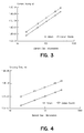
- FIG. 3 is a graphical illustration of the amount of heat required to heat the microthruster from 300° Kelvin at 10 atmospheres to 1500° at 50 atmospheres for both helium and carbon dioxide gases.
- the vertical axis represents the elemental heating in nano Joules to the heat element, while the horizontal axis illustrates the size of the element in micrometers, varying from 10 to 1,000 micrometers. As illustrated in FIG. 3, more heating is required for carbon dioxide gas than for helium gas. Moreover, as expected, the amount of heating varies as a function of the size of the microthruster.
- FIG. 4 is a graphical illustration of the predicted blow-down time for microthrusters using helium gas and carbon dioxide gas as a function of the size of the microthruster 20.
- the vertical axis represents the emptying time in milliseconds, while the horizontal axis represents the size of the microthruster in micrometers.
- the helium gas empties more quickly than the carbon dioxide, and, as expected, the emptying time is greater for larger size microthrusters 20.
- the microthruster 20 may be fabricated using various micromachining techniques, including laser micromachining techniques, as well as batch processing techniques normally used for microelectronics.
- the microthruster 20 is adapted to be fabricated using microelectromechnical system (MEMS) techniques, such as bulk anisotropic etching of mono-crystalline silicon (or other substrates), or plasma etching, or reactive ion etching, a deposition, patterning and removal of layers applied to a substrate, or laser machining.
- MEMS microelectromechnical system
Landscapes
- Engineering & Computer Science (AREA)
- Mechanical Engineering (AREA)
- General Engineering & Computer Science (AREA)
- Chemical & Material Sciences (AREA)
- Combustion & Propulsion (AREA)
- Physics & Mathematics (AREA)
- Fluid Mechanics (AREA)
- Micromachines (AREA)
- Reciprocating Pumps (AREA)
Applications Claiming Priority (2)
| Application Number | Priority Date | Filing Date | Title |
|---|---|---|---|
| US912709 | 1997-08-18 | ||
| US08/912,709 US6131385A (en) | 1997-08-18 | 1997-08-18 | Integrated pulsed propulsion system for microsatellite |
Publications (2)
| Publication Number | Publication Date |
|---|---|
| EP0903487A2 true EP0903487A2 (fr) | 1999-03-24 |
| EP0903487A3 EP0903487A3 (fr) | 1999-11-03 |
Family
ID=25432310
Family Applications (1)
| Application Number | Title | Priority Date | Filing Date |
|---|---|---|---|
| EP19980113282 Withdrawn EP0903487A3 (fr) | 1997-08-18 | 1998-07-16 | Système intégré de propulsion impulsionnelle pour microsatellite |
Country Status (3)
| Country | Link |
|---|---|
| US (1) | US6131385A (fr) |
| EP (1) | EP0903487A3 (fr) |
| JP (1) | JP3172140B2 (fr) |
Cited By (16)
| Publication number | Priority date | Publication date | Assignee | Title |
|---|---|---|---|---|
| WO2002001078A1 (fr) * | 2000-06-30 | 2002-01-03 | Etienne Lacroix Tous Artifices S.A. | Actionneur a base de micro-impulseurs pyrotechniques |
| US6431594B1 (en) | 2001-01-05 | 2002-08-13 | Trw Vehicle Safety Systems Inc. | Air bag inflator with mechanism for deactivation of second stage and autoignition |
| DE10161955A1 (de) * | 2001-01-08 | 2003-05-28 | Trw Inc | Sitzgurtband-Vorspannvorrichtung, die MEMS-Einrichtungen verwendet |
| US6584911B2 (en) | 2001-04-26 | 2003-07-01 | Trw Inc. | Initiators for air bag inflators |
| US6598899B2 (en) | 2001-08-21 | 2003-07-29 | Trw Inc. | Inflatable seat belt using MEMS devices |
| US6619692B2 (en) | 2001-03-27 | 2003-09-16 | Trw Inc. | Air bag inflators |
| US6983955B2 (en) | 2001-01-05 | 2006-01-10 | Trw Inc. | Air bag inflators |
| WO2010068174A1 (fr) * | 2008-12-10 | 2010-06-17 | Guilio Manzoni | Microsatellite comprenant un module de propulsion et un dispositif d'imagerie |
| US7793592B2 (en) | 2002-02-06 | 2010-09-14 | Trw Airbag Systems Gmbh | Microelectronic pyrotechnical component |
| CN104358663A (zh) * | 2014-09-19 | 2015-02-18 | 浙江大学 | 一种用于皮纳卫星的液氨推进系统 |
| US9228570B2 (en) | 2010-02-16 | 2016-01-05 | University Of Florida Research Foundation, Inc. | Method and apparatus for small satellite propulsion |
| CN105888884A (zh) * | 2016-04-15 | 2016-08-24 | 上海微小卫星工程中心 | 一种微小卫星的微推进器芯片 |
| US9820369B2 (en) | 2013-02-25 | 2017-11-14 | University Of Florida Research Foundation, Incorporated | Method and apparatus for providing high control authority atmospheric plasma |
| DE102017102481A1 (de) | 2017-02-08 | 2018-08-09 | Klaus Schilling | Formationsfähiger Kleinstsatellit und Formation aus mehreren Kleinstsatelliten |
| US10219364B2 (en) | 2017-05-04 | 2019-02-26 | Nxp Usa, Inc. | Electrostatic microthruster |
| US10236163B1 (en) | 2017-12-04 | 2019-03-19 | Nxp Usa, Inc. | Microplasma generator with field emitting electrode |
Families Citing this family (16)
| Publication number | Priority date | Publication date | Assignee | Title |
|---|---|---|---|---|
| US6398490B1 (en) | 1999-01-04 | 2002-06-04 | California Institute Of Technology | Oscillating microturbine |
| US6487844B1 (en) * | 1999-11-24 | 2002-12-03 | Trw Inc. | Aerospike augmentation of microthruster impulse |
| RU2193100C2 (ru) * | 2000-06-21 | 2002-11-20 | Федеральное государственное унитарное предприятие "Конструкторское бюро "Арсенал" им. М.В.Фрунзе | Электровзрывной ракетный двигатель |
| EP1347390A4 (fr) | 2000-12-28 | 2009-04-08 | Future System Consulting Corp | Systeme de structure |
| US6539703B1 (en) | 2001-09-05 | 2003-04-01 | Trw Inc. | Spacecraft component with microthruster actuation and operation thereof |
| US6622629B2 (en) | 2001-10-17 | 2003-09-23 | Northrop Grumman Corporation | Submunition fuzing and self-destruct using MEMS arm fire and safe and arm devices |
| US6774337B2 (en) * | 2002-10-21 | 2004-08-10 | Lockheed Martin Corporation | Method for protecting the diaphragm and extending the life of SiC and/or Si MEMS microvalves |
| US6892525B2 (en) | 2003-06-06 | 2005-05-17 | Honeywell International Inc. | Micropump-based microthruster |
| US20050232817A1 (en) * | 2003-09-26 | 2005-10-20 | The University Of Cincinnati | Functional on-chip pressure generator using solid chemical propellant |
| US7958823B2 (en) * | 2004-12-17 | 2011-06-14 | Sawka Wayne N | Controllable digital solid state cluster thrusters for rocket propulsion and gas generation |
| US8613188B2 (en) | 2008-05-14 | 2013-12-24 | Purdue Research Foundation | Method of enhancing microthruster performance |
| US20110226148A1 (en) * | 2008-05-16 | 2011-09-22 | Sawka Wayne N | Physical destruction of electrical device and methods for triggering same |
| KR101165303B1 (ko) | 2011-01-31 | 2012-07-19 | 국방과학연구소 | 마이크로 코일 및 그 제조 방법 |
| US9334068B2 (en) | 2014-04-04 | 2016-05-10 | NOA Inc. | Unified orbit and attitude control for nanosatellites using pulsed ablative thrusters |
| CN107975462B (zh) * | 2016-10-21 | 2020-06-19 | 南京理工大学 | 电热微推力器 |
| CN115419518A (zh) * | 2022-08-16 | 2022-12-02 | 西北工业大学 | 一种基于3d打印的尼龙壳体与金属喷管的微推进器 |
Family Cites Families (8)
| Publication number | Priority date | Publication date | Assignee | Title |
|---|---|---|---|---|
| US3316719A (en) * | 1965-03-11 | 1967-05-02 | Curtiss Wright Corp | Expansible rocket engines |
| DE3034257C2 (de) * | 1980-09-11 | 1983-07-07 | Repa Feinstanzwerk Gmbh, 7071 Alfdorf | Pyrotechnische Antriebseinrichtung insbesondere für eine Rückstrammvorrichtung eines Sicherheitsgurtsystems |
| USH795H (en) * | 1989-12-04 | 1990-07-03 | The United States Of America As Represented By The Secretary Of The Army | Reduced temperature sensitivity launch motor |
| DE4415259C1 (de) * | 1994-04-30 | 1995-06-08 | Daimler Benz Aerospace Ag | Schuberzeugungsvorrichtung |
| JPH08226790A (ja) * | 1995-02-20 | 1996-09-03 | Japan Steel Works Ltd:The | 電熱化学ロケット砲 |
| DE19524094A1 (de) * | 1995-07-01 | 1997-01-02 | Temic Bayern Chem Airbag Gmbh | Pyrotechnikfreier Gasgenerator |
| JPH09209916A (ja) * | 1996-01-29 | 1997-08-12 | Toshiba Corp | 移動装置 |
| WO1998022719A1 (fr) * | 1996-11-21 | 1998-05-28 | Laboratoires D'hygiene Et De Dietetique (L.H.D.) | Vanne miniature pour le remplissage du reservoir d'un appareil d'administration transdermique de medicament |
-
1997
- 1997-08-18 US US08/912,709 patent/US6131385A/en not_active Expired - Fee Related
-
1998
- 1998-07-16 EP EP19980113282 patent/EP0903487A3/fr not_active Withdrawn
- 1998-08-11 JP JP22670398A patent/JP3172140B2/ja not_active Expired - Fee Related
Non-Patent Citations (2)
| Title |
|---|
| S.W JANSON, H.HELVAJIAN: "Batch-Fabricated Microthrusters: Initial Results", AMERICAN INSTITUTE OF AREONAUTICS AND ASTRONAUTICS,INC., 1 January 1996 (1996-01-01) |
| S.W JANSON: "Chemical and Electric Micropropultion Concepts For Nanosatellites", AMERICAN INSTITUTE OF AERONAUTICS AND ASTRONAUTICS, INC, 1 January 1994 (1994-01-01) |
Cited By (23)
| Publication number | Priority date | Publication date | Assignee | Title |
|---|---|---|---|---|
| FR2811036A1 (fr) * | 2000-06-30 | 2002-01-04 | Lacroix Soc E | Actionneur a base de micro-impulseurs pyrotechniques |
| WO2002001078A1 (fr) * | 2000-06-30 | 2002-01-03 | Etienne Lacroix Tous Artifices S.A. | Actionneur a base de micro-impulseurs pyrotechniques |
| US6431594B1 (en) | 2001-01-05 | 2002-08-13 | Trw Vehicle Safety Systems Inc. | Air bag inflator with mechanism for deactivation of second stage and autoignition |
| US6983955B2 (en) | 2001-01-05 | 2006-01-10 | Trw Inc. | Air bag inflators |
| DE10161955A1 (de) * | 2001-01-08 | 2003-05-28 | Trw Inc | Sitzgurtband-Vorspannvorrichtung, die MEMS-Einrichtungen verwendet |
| US6641074B2 (en) | 2001-01-08 | 2003-11-04 | Trw Inc. | Seat belt webbing pretensioner using MEMS devices |
| US6619692B2 (en) | 2001-03-27 | 2003-09-16 | Trw Inc. | Air bag inflators |
| DE10210587B4 (de) * | 2001-03-27 | 2006-05-04 | Trw Inc., Lyndhurst | Airbagaufblasvorrichtungen |
| US6584911B2 (en) | 2001-04-26 | 2003-07-01 | Trw Inc. | Initiators for air bag inflators |
| US6598899B2 (en) | 2001-08-21 | 2003-07-29 | Trw Inc. | Inflatable seat belt using MEMS devices |
| US7793592B2 (en) | 2002-02-06 | 2010-09-14 | Trw Airbag Systems Gmbh | Microelectronic pyrotechnical component |
| WO2010068174A1 (fr) * | 2008-12-10 | 2010-06-17 | Guilio Manzoni | Microsatellite comprenant un module de propulsion et un dispositif d'imagerie |
| US8967545B2 (en) | 2008-12-10 | 2015-03-03 | Giulio Manzoni | Microsatellite comprising a propulsion module and an imaging device |
| US9228570B2 (en) | 2010-02-16 | 2016-01-05 | University Of Florida Research Foundation, Inc. | Method and apparatus for small satellite propulsion |
| US9820369B2 (en) | 2013-02-25 | 2017-11-14 | University Of Florida Research Foundation, Incorporated | Method and apparatus for providing high control authority atmospheric plasma |
| CN104358663A (zh) * | 2014-09-19 | 2015-02-18 | 浙江大学 | 一种用于皮纳卫星的液氨推进系统 |
| CN104358663B (zh) * | 2014-09-19 | 2017-03-22 | 浙江大学 | 一种用于皮纳卫星的液氨推进系统 |
| CN105888884A (zh) * | 2016-04-15 | 2016-08-24 | 上海微小卫星工程中心 | 一种微小卫星的微推进器芯片 |
| DE102017102481A1 (de) | 2017-02-08 | 2018-08-09 | Klaus Schilling | Formationsfähiger Kleinstsatellit und Formation aus mehreren Kleinstsatelliten |
| WO2018146220A1 (fr) | 2017-02-08 | 2018-08-16 | Klaus Schilling | Petit satellite pouvant être mis en formation et formation constituée de plusieurs petits satellites |
| US11104456B2 (en) | 2017-02-08 | 2021-08-31 | Klaus Schilling | Small satellite capable of formation flying, and formation of multiple small satellites |
| US10219364B2 (en) | 2017-05-04 | 2019-02-26 | Nxp Usa, Inc. | Electrostatic microthruster |
| US10236163B1 (en) | 2017-12-04 | 2019-03-19 | Nxp Usa, Inc. | Microplasma generator with field emitting electrode |
Also Published As
| Publication number | Publication date |
|---|---|
| EP0903487A3 (fr) | 1999-11-03 |
| US6131385A (en) | 2000-10-17 |
| JP3172140B2 (ja) | 2001-06-04 |
| JPH11105796A (ja) | 1999-04-20 |
Similar Documents
| Publication | Publication Date | Title |
|---|---|---|
| US6131385A (en) | Integrated pulsed propulsion system for microsatellite | |
| Rossi et al. | Design, fabrication and modelling of MEMS-based microthrusters for space application | |
| Köhler et al. | A hybrid cold gas microthruster system for spacecraft | |
| Tanaka et al. | MEMS-based solid propellant rocket array thruster | |
| US12578035B2 (en) | Microelectronic thermal valve | |
| Rossi | Micropropulsion for space—a survey of MEMS‐based micro thrusters and their solid propellant technology | |
| Ketsdever et al. | Performance testing of a microfabricated propulsion system for nanosatellite applications | |
| EP3831725B1 (fr) | Propulseur de gaz à froid à propergol solide | |
| Huh et al. | Fabrication of a liquid monopropellant microthruster with built-in regenerative micro-cooling channels | |
| Janson et al. | Microtechnology for space systems | |
| Nguyen et al. | The merits of cold gas micropropulsion in state-of-the-art space missions | |
| US6487844B1 (en) | Aerospike augmentation of microthruster impulse | |
| US6539703B1 (en) | Spacecraft component with microthruster actuation and operation thereof | |
| CN1282823C (zh) | 带压力传感器的微型化学推进器 | |
| Rangsten et al. | Closed-loop thrust control in a MEMS-based micro propulsion module for CubeSats | |
| Wilburn | Advancing Asteroid Surface Exploration Using Sublimate-Based Regenerative Micropropulsion and 3D Path Planning | |
| Janson et al. | Development of an Inspector Satellite Propulsion Module Using Photostructurable Glass/Ceramic Materials | |
| Rangsten et al. | MEMS micropropulsion components for small spacecraft | |
| Ye et al. | A vaporizing water micro-thruster | |
| Grönland et al. | MEMS technology to achieve miniaturization, redundancy, and new functionality in space | |
| Kim | A New Era of Space Shuttle | |
| Eriksson et al. | Cold gas micro thrusters | |
| Rangsten et al. | Advanced MEMS components in closed-loop micro propulsion applications | |
| Fujita et al. | Preliminary Study of Venus Exploration with Aerocapture System | |
| Rezkallah et al. | Recent Development in the Studies of Annular Two-Phase Flow at Microgravity |
Legal Events
| Date | Code | Title | Description |
|---|---|---|---|
| PUAI | Public reference made under article 153(3) epc to a published international application that has entered the european phase |
Free format text: ORIGINAL CODE: 0009012 |
|
| AK | Designated contracting states |
Kind code of ref document: A2 Designated state(s): DE FR GB IT |
|
| AX | Request for extension of the european patent |
Free format text: AL;LT;LV;MK;RO;SI |
|
| PUAL | Search report despatched |
Free format text: ORIGINAL CODE: 0009013 |
|
| AK | Designated contracting states |
Kind code of ref document: A3 Designated state(s): AT BE CH CY DE DK ES FI FR GB GR IE IT LI LU MC NL PT SE |
|
| AX | Request for extension of the european patent |
Free format text: AL;LT;LV;MK;RO;SI |
|
| 17P | Request for examination filed |
Effective date: 19991125 |
|
| AKX | Designation fees paid |
Free format text: DE FR GB IT |
|
| 17Q | First examination report despatched |
Effective date: 20020325 |
|
| STAA | Information on the status of an ep patent application or granted ep patent |
Free format text: STATUS: THE APPLICATION IS DEEMED TO BE WITHDRAWN |
|
| 18D | Application deemed to be withdrawn |
Effective date: 20020806 |