EP0902998B1 - Transformer with protection device - Google Patents
Transformer with protection device Download PDFInfo
- Publication number
- EP0902998B1 EP0902998B1 EP97924159A EP97924159A EP0902998B1 EP 0902998 B1 EP0902998 B1 EP 0902998B1 EP 97924159 A EP97924159 A EP 97924159A EP 97924159 A EP97924159 A EP 97924159A EP 0902998 B1 EP0902998 B1 EP 0902998B1
- Authority
- EP
- European Patent Office
- Prior art keywords
- transformer
- voltage
- ground
- transient
- neutral
- Prior art date
- Legal status (The legal status is an assumption and is not a legal conclusion. Google has not performed a legal analysis and makes no representation as to the accuracy of the status listed.)
- Expired - Lifetime
Links
- 238000004804 winding Methods 0.000 claims description 41
- 230000007935 neutral effect Effects 0.000 claims description 26
- 230000001052 transient effect Effects 0.000 claims description 26
- 229910044991 metal oxide Inorganic materials 0.000 claims description 5
- 150000004706 metal oxides Chemical class 0.000 claims description 5
- 239000004020 conductor Substances 0.000 claims description 4
- 230000000694 effects Effects 0.000 claims description 4
- 230000001131 transforming effect Effects 0.000 claims description 4
- 238000000034 method Methods 0.000 claims description 3
- 230000008878 coupling Effects 0.000 claims 1
- 238000010168 coupling process Methods 0.000 claims 1
- 238000005859 coupling reaction Methods 0.000 claims 1
- 238000009434 installation Methods 0.000 description 10
- 239000002184 metal Substances 0.000 description 5
- 230000015556 catabolic process Effects 0.000 description 4
- 230000005611 electricity Effects 0.000 description 4
- 230000007246 mechanism Effects 0.000 description 4
- 238000009413 insulation Methods 0.000 description 3
- 230000005540 biological transmission Effects 0.000 description 2
- 238000011835 investigation Methods 0.000 description 2
- 238000010791 quenching Methods 0.000 description 2
- 241000555745 Sciuridae Species 0.000 description 1
- 206010042255 Struck by lightning Diseases 0.000 description 1
- 230000009471 action Effects 0.000 description 1
- 230000002411 adverse Effects 0.000 description 1
- 238000010276 construction Methods 0.000 description 1
- 230000007423 decrease Effects 0.000 description 1
- 238000010891 electric arc Methods 0.000 description 1
- 238000012986 modification Methods 0.000 description 1
- 230000004048 modification Effects 0.000 description 1
- 238000010587 phase diagram Methods 0.000 description 1
- 230000002028 premature Effects 0.000 description 1
- 230000000171 quenching effect Effects 0.000 description 1
- 230000004044 response Effects 0.000 description 1
- 230000000630 rising effect Effects 0.000 description 1
Images
Classifications
-
- H—ELECTRICITY
- H02—GENERATION; CONVERSION OR DISTRIBUTION OF ELECTRIC POWER
- H02H—EMERGENCY PROTECTIVE CIRCUIT ARRANGEMENTS
- H02H7/00—Emergency protective circuit arrangements specially adapted for specific types of electric machines or apparatus or for sectionalised protection of cable or line systems, and effecting automatic switching in the event of an undesired change from normal working conditions
- H02H7/04—Emergency protective circuit arrangements specially adapted for specific types of electric machines or apparatus or for sectionalised protection of cable or line systems, and effecting automatic switching in the event of an undesired change from normal working conditions for transformers
-
- H—ELECTRICITY
- H02—GENERATION; CONVERSION OR DISTRIBUTION OF ELECTRIC POWER
- H02B—BOARDS, SUBSTATIONS OR SWITCHING ARRANGEMENTS FOR THE SUPPLY OR DISTRIBUTION OF ELECTRIC POWER
- H02B5/00—Non-enclosed substations; Substations with enclosed and non-enclosed equipment
- H02B5/01—Earthing arrangements, e.g. earthing rods
Definitions
- This invention relates generally to improvements in or relating to electrical power distribution and more particularly concerns the protection of power distribution transformers, as are used in the UK and elsewhere for transforming the high voltages employed for power transmission to the low voltages utilized at domestic and industrial installations, against the adverse effects of lightning strikes.
- the invention is particularly, but not exclusively, concerned with pole mounted electrical power distribution transformers.
- a surge diverter is a device such as an arc gap for example which is normally very high resistance but which provides a low resistance through path under high voltage.
- transformers can suffer damage by lightning strikes despite the provision of high voltage surge diverter protection has not been understood and has been the subject of much discussion over a considerable number of years.
- Transformers are relatively expensive devices and their failure gives rise to significant expense not only in replacement costs, but also arising out of the disruption that is caused to electricity users by the failure of their electricity supply.
- GB-A-390 102 describes a number of measures for protecting distribution transformers from lightning strikes.
- a discharge gap having a breakdown voltage less than the breakdown strength of the transformer insulation is placed in the circuit to protect the transformer and drain off surge voltages, the arrangement for distribution transformers comprising the provision of a flashover point, in the form of stud type bushings, between the transformer winding and the transformer casing.
- this arrangement which necessitates that the transformer casing be connected to ground, is said in GB-A-390 102 to be undesirable since it exposes workmen to hazard and does not provide for quenching of the arc when flashover does occur.
- the invention of GB-A-390 102 provides for high tension electrical discharge devices to be connected between each of the terminals on the high tension winding of the transformer and the transformer tank, and a low tension electrical discharge device to be connected between the tank and the grounded neutral of the low tension winding.
- Resistance elements are proposed to be provided in series with each discharge device for limiting follow current, and a self-quenching arc gap type discharge device combined with a resistor element is described.
- the high-tension discharge devices are said to have a breakdown voltage sufficiently high that an arc discharge will not be initiated by the customary dynamic voltage applied to the high tension line, and the low tension discharge device is said to have a cut-off voltage higher than the normal crest voltage of the low tension winding.
- a conventional distribution transformer installation in the UK will typically be pole mounted with a casing earth connected to the metal transformer casing and running down the pole to where it is connected to a number of metal ground rods which are knocked into the ground at the base of the pole.
- Each high voltage transformer termination there being one such termination for each phase of a 3-phase transformer and there being two such terminations for a single phase transformer, has connected thereto a respective surge diverter or surge arrester device providing a path to ground via the transformer casing and the casing earth for lightning strike transients.
- a neutral termination On the low voltage side of the transformer there are corresponding terminations and there is additionally a neutral termination, and the neutral termination is connected to a neutral earth conductor which runs down the pole and is connected to a neutral ground constituted by one or more metal rods knocked into the ground.
- this neutral earth should be located between 3 and 5 metres distance from the transformer casing earth.
- the resistance to ground of the transformer casing earth is typically of the order of 10 ohms.
- the associated surge diverter(s) operate(s) to protect the high voltage winding of the transformer. This results in, typically, a 10KAmp 8/20 ⁇ secs current flowing through the surge diverter(s) to ground via the typically 10 ohms transformer casing earth.
- An 8/20 ⁇ secs transient current is one which peaks after 8 ⁇ secs and decreases to half its peak value in 20 ⁇ secs.
- the solution to the problem of how to avoid such failures clearly is to provide overvoltage protection for the low voltage winding and this can be achieved by provision of a transient voltage clamping device, for example a suitably high voltage rated surge arrester device as described in GB-B-2 188 199, connected between the low voltage neutral and the transformer casing.
- a transient voltage clamping device for example a suitably high voltage rated surge arrester device as described in GB-B-2 188 199, connected between the low voltage neutral and the transformer casing.
- the surge arrester device must have a high voltage rating because the use of a surge arrester with a continuous operating voltage equal to or not substantially greater than the low voltage supply, this being the teaching of GB-A-390 102, would not be satisfactory as premature failure of the arrester would occur in the event of a phase-to-earth fault arising on the high voltage side of the transformer.
- Electric power distribution systems incorporate auto-reclosing circuit breaker devices which, in response to a sensed ground (earth) fault current on a power line caused for example by a squirrel shorting out a termination on the high voltage side of a transformer, will initially break the respective circuit for a period of typically 10 seconds (dead time) and will then automatically re-close and re-energize the circuit. Should the circuit still have a permanent earth fault on it the protection may take up to 10 seconds before opening the circuit breaker.
- the transient voltage clamping device that is provided for protection of the low voltage winding must be able to withstand, without failure, the voltage to which it would be subjected in such an event.
- the device in order for a transient voltage clamping device coupled between the low voltage neutral termination of the transformer winding and the transformer casing to be capable of providing the requisite protection, the device must fulfil the following requirements, namely:
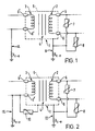
- this represents a single phase of a typical 3-phase transformer installation as presently employed in the UK for transforming the 11kV power transmission voltage to a phase-to-phase service voltage of 400V.
- Other phases of the installation have an equivalent structure.
- the three phase windings on the high voltage side of the transformer will conventionally be connected in delta configuration, and the three phase windings on the low voltage side will conventionally be star connected with the neutral point grounded.
- the transformer 1 consists of high voltage and low voltage windings 2 and 3, respectively, upon a core structure 4, these being contained in an oil-filled or otherwise insulated metal casing or tank 5 which carries shedded insulating terminations 6 and 6' for the respective windings.
- Transformers of this kind are manufactured to British Electrical Supply Standards Institute Standard 35-1 and are available from South Wales Transformers, Treforest, Mid Glamorgan, Wales for example.
- High voltage surge arresters or diverters 7 and 8 are conventionally coupled between the high voltage terminations of the transformer and the transformer casing and may for example comprise duplex arc gaps.
- the transformer casing is grounded as aforementioned at ground connection II and a ground resistance R c-e of the order of 10 ohms is typical. It is conventional furthermore to provide a separate ground 12 for the neutral termination of the low voltage transformer winding and this gives rise to a resistance R n-e of the same order of magnitude as R c-e .
- the surge arrester 7 In the event of a lightning strike on a power line connected to the high voltage side of the transformer, the surge arrester 7 for example will operate to pass the lightning transient to.ground.
- a current typically of 10KA flows through the surge arrester 7 for a period of 8 to 20 ⁇ secs and, given the ground resistance R c-e of 10 ohms, the transformer casing transiently is elevated to a voltage of 100kV.
- This 100kV casing voltage appears between the transformer casing and the grounded low voltage winding 3 of the transformer and, as mentioned hereinbefore, exceeds the typically 25kV withstand voltage of the low voltage windings. Transformer failure then results as a flashover occurs between the transformer casing and the low voltage winding.
- the high voltage winding of the transformer can also be damaged as the step-up ratio of the transformer causes a much higher voltage transient to be imposed on the high voltage windings as a result of the 100kV transient on the low voltage winding.
- FIG 2 which otherwise is the same as Figure 1, shows the provision of a transient voltage clamping device constituted by a high voltage surge arrester 10 coupled between the neutral termination of the low voltage winding 3 of the transformer and the transformer casing 5.
- the high voltage surge arrester 10 will provide a preferred discharge path as compared for example to a path from the transformer casing through the insulating medium or over the low voltage terminations of the transformer to the grounded low voltage winding. Provision of the high voltage surge arrester 10 thus protects the low voltage side of the transformer.
- the high voltage surge arrester 10 must clamp the transformer casing to a voltage not exceeding the voltage withstand of the low voltage winding.
- the low voltage winding of an E.S.I. Standard 35-1 distribution class transformer has a voltage withstanding rating of 25kV, which means that the surge arrester 10 should preferably be selected to clamp the transformer casing to no greater than say 20kV under lightning strike conditions.
- the arrester 10 should be able to withstand without failure a ground fault condition on the high voltage side of the transformer for a predetermined time period, eg. 10 seconds.
- Such a ground fault condition caused for example by shorting out of one of the transformer high voltage terminations to the transformer casing, puts the high tension line voltage onto the transformer casing and gives rise to a corresponding voltage across the surge arrester 10.
- Circuit breakers in the distribution system will not permit this condition to prevail for more than a predetermined time period, 10 seconds in the case of the 11kV power distribution system utilized in the UK, and the surge arrester 10 must be able to withstand the corresponding voltage loading of 7kV (11kV ⁇ ⁇ 3) for this period.
- a standard 6kV rated surge arrester Type No. EGA6 manufactured by Bowthorpe EMP Limited of Brighton, London, England in accordance with the teachings of GB-B-2 188 199 meets these requirements.
- the surge diverters 7 and 8 are constituted by metal oxide surge arresters such as are described in GB-B-2 188 199 for example.
- spark gaps may be provided in parallel with the high voltage surge arresters 7, 8 for the purpose of ensuring that a path to ground remains for fault current in the event of surge arrester failure. The provision of such spark gaps has substantially no affect upon the present invention.
- the Bowthorpe EMP Limited surge arrester Type No. EGA6 may be considered to be "over engineered” for the application of the present invention and an alternative, more simple surge arrester configuration may be preferred for the surge arrester 10 shown in Figure 2.
- the surge arresters 7 and 8 shown in Figure 2 are of the metal oxide varistor type exemplified by the surge arrester described in GB-B-2 188 199, they could simply be constituted by arc gap devices, for example duplex gaps.
Landscapes
- Engineering & Computer Science (AREA)
- Power Engineering (AREA)
- Emergency Protection Circuit Devices (AREA)
- Gas-Insulated Switchgears (AREA)
- Regulation Of General Use Transformers (AREA)
Description
Claims (14)
- A transformer (1) in or for an electrical power distribution system for transforming the high distribution voltage of the system into a low service voltage, the transformer having a ground connection (11) and the high voltage side (2) of the transformer including a surge diverter (7,8) connected between each high voltage termination (6) of the transformer and said ground connection (11), and the transformer having a neutral termination (6') on its low voltage side (3), whereby a transient voltage clamping device (10) is coupled between said neutral termination (6') and said ground connection (11), characterized in that said transient voltage clamping device (10) being selected so as to be capable of clamping the voltage at said neutral termination (6') to below the withstand voltage of the low voltage transformer winding (3) when, in use of the transformer, a lightning strike on the high voltage side (2) of the transformer causes one or more of said surge diverters (7,8) to operate so as to discharge the lightning strike to ground and thereby subject the transformer ground connection (11) to a transient high voltage.
- A transformer as claimed in claim 1 wherein the withstand voltage of the low voltage transformer winding (3) is of the order of 25kV, and the transient voltage clamping device (10) that is coupled between said neutral termination (6') and said ground connection (11) is adapted to clamp the voltage at said neutral termination (6') to a voltage of the order of 20kV.
- A transformer as claimed in claim 1 or 2 wherein the transient voltage clamping device (10) that is coupled between said neutral termination (6') and said ground connection (11) is selected so as to be capable of withstanding for a predetermined time period the voltage to which it would be subjected under a ground fault condition on the high voltage side (2) of the transformer.
- A transformer as claimed in claim 3 wherein the high distribution voltage of the system is of the order of 11kV and the transient voltage clamping device (10) that is coupled between said neutral termination (6') and said ground connection (11) is selected so as to be capable of withstanding a voltage of the order of 7kV.
- A transformer as claimed in claim 3 or 4 wherein said predetermined time period is about 10 seconds.
- A single-phase transformer as claimed in any of the preceding claims.
- A three-phase transformer as claimed in any of claims 1 to 5.
- A transformer as claimed in any of the preceding claims wherein said neutral terminal (6') is connected to ground potential.
- A transformer as claimed in claim 8 wherein the connection of said neutral terminal (6') to ground is by way of a conductor separate from the connection of said ground connection (11) of the transformer to ground.
- A transformer as claimed in any of the preceding claims wherein said surge diverters (7,8) comprise arc gap devices.
- A transformer as claimed in any of claims 1 to 9 wherein said surge diverters (7,8) comprise metal oxide varistor surge arresters.
- A transformer as claimed in any of the preceding claims wherein said transient voltage clamping device (10) comprises a metal oxide varistor surge arrester.
- An electrical power distribution system comprising a pole mounted transformer (1) according to any of the preceding claims and wherein low voltage surge arresters are provided on a next adjacent pole downstream of the low voltage side (3) of the transformer, said low voltage surge arresters coupling the low voltage lines to ground.
- A method of protecting a distribution transformer in an electric power distribution system against the effect of a lightning strike, said electric power distribution system incorporating auto-reclosing circuit breaker devices responsive to a sensed ground fault current on a power line connected to the high voltage side of the transformer to temporarily break the respective circuit for a period of time before automatically reclosing and re-energizing the circuit to test for continuance of said ground fault whereupon, after a certain period of time and if the ground fault continues, the circuit breaker devices will again be opened, said distribution transformer having a grounded casing (4) and said method including connecting a transient voltage clamping device (10) between the neutral (6') of the low voltage winding (3) of the transformer and the grounded transformer casing (4), and being characterized by said transient voltage clamping device (10) being selected (a) to limit the transient voltage at the transformer casing (4) to below the withstand voltage of the low voltage transformer winding (3) in the event of a lightning strike and (b) to be capable of withstanding for said period of time a ground fault condition at the high voltage side (2) of the transformer.
Priority Applications (1)
| Application Number | Priority Date | Filing Date | Title |
|---|---|---|---|
| DK97924159T DK0902998T3 (en) | 1996-06-04 | 1997-06-03 | Transformer with protective device |
Applications Claiming Priority (3)
| Application Number | Priority Date | Filing Date | Title |
|---|---|---|---|
| GB9611623 | 1996-06-04 | ||
| GBGB9611623.1A GB9611623D0 (en) | 1996-06-04 | 1996-06-04 | Improvements relating to electrical power distribution |
| PCT/GB1997/001494 WO1997047064A1 (en) | 1996-06-04 | 1997-06-03 | Transformer with protection device |
Publications (2)
| Publication Number | Publication Date |
|---|---|
| EP0902998A1 EP0902998A1 (en) | 1999-03-24 |
| EP0902998B1 true EP0902998B1 (en) | 2004-10-27 |
Family
ID=10794720
Family Applications (1)
| Application Number | Title | Priority Date | Filing Date |
|---|---|---|---|
| EP97924159A Expired - Lifetime EP0902998B1 (en) | 1996-06-04 | 1997-06-03 | Transformer with protection device |
Country Status (12)
| Country | Link |
|---|---|
| EP (1) | EP0902998B1 (en) |
| AU (1) | AU728048B2 (en) |
| DE (1) | DE69731381T2 (en) |
| DK (1) | DK0902998T3 (en) |
| ES (1) | ES2231869T3 (en) |
| GB (3) | GB9611623D0 (en) |
| MY (1) | MY125543A (en) |
| NO (1) | NO319911B1 (en) |
| NZ (1) | NZ333449A (en) |
| PT (1) | PT902998E (en) |
| WO (1) | WO1997047064A1 (en) |
| ZA (1) | ZA974865B (en) |
Cited By (2)
| Publication number | Priority date | Publication date | Assignee | Title |
|---|---|---|---|---|
| WO2014071479A1 (en) * | 2012-11-12 | 2014-05-15 | Evoluções Energia Ltda | Electromagnetic earth-electron pickup device for generating electricity |
| CN106610444A (en) * | 2015-10-21 | 2017-05-03 | 新巨企业股份有限公司 | surge current recording module |
Families Citing this family (3)
| Publication number | Priority date | Publication date | Assignee | Title |
|---|---|---|---|---|
| CN103368164B (en) * | 2012-04-01 | 2016-08-17 | 华为终端有限公司 | A kind of lightning protection circuit, Switching Power Supply and lightening arresting method |
| US9882373B2 (en) | 2014-11-21 | 2018-01-30 | Abb Schweiz Ag | System for protection of dry type transformers |
| US11355925B2 (en) * | 2018-01-30 | 2022-06-07 | Hitachi Energy Switzerland Ag | System design solution for DC grid cost reduction and risk minimization |
Family Cites Families (10)
| Publication number | Priority date | Publication date | Assignee | Title |
|---|---|---|---|---|
| GB309102A (en) * | 1927-12-31 | 1929-04-02 | Ig Farbenindustrie Ag | Process for the manufacture of condensation products of the benzo-diazine series |
| GB390102A (en) * | 1931-12-01 | 1933-03-30 | Westinghouse Electric & Mfg Co | Improvements in or relating to surge-proof electrical transformers |
| GB441987A (en) * | 1934-08-17 | 1936-01-30 | British Thomson Houston Co Ltd | Improvements in and relating to protective devices for electric circuits |
| US3825866A (en) * | 1972-06-29 | 1974-07-23 | N Piccione | System and apparatus for underground transformer installation |
| DE2934235A1 (en) * | 1979-08-24 | 1981-03-26 | Ant Nachrichtentechnik Gmbh, 71522 Backnang | MAINS CONNECTION WITH SURGE PROTECTORS |
| US4604673A (en) * | 1984-05-14 | 1986-08-05 | General Electric Company | Distribution transformer with surge protection device |
| DK173921B1 (en) * | 1986-01-29 | 2002-02-18 | Bowthorpe Ind Ltd | Electric surge arrester, method and apparatus for making and using such a device |
| US4881147A (en) * | 1987-03-02 | 1989-11-14 | Schaff Jean Paul | Protection of sensitive electrical installations against the effects of lightning, and devices proposed for such arrangement |
| GB8820953D0 (en) * | 1988-09-07 | 1988-10-05 | Furse W J & Co Ltd | Apparatus suitable for use in protecting electrical installations from transients |
| US5184270A (en) * | 1990-06-13 | 1993-02-02 | Abb Power T&D Company, Inc. | Internal arc gap for secondary side surge protection and dissipation of a generated arc |
-
1996
- 1996-06-04 GB GBGB9611623.1A patent/GB9611623D0/en active Pending
-
1997
- 1997-06-03 ZA ZA9704865A patent/ZA974865B/en unknown
- 1997-06-03 GB GB9928806A patent/GB2342516B/en not_active Expired - Lifetime
- 1997-06-03 DE DE69731381T patent/DE69731381T2/en not_active Expired - Fee Related
- 1997-06-03 AU AU29723/97A patent/AU728048B2/en not_active Expired
- 1997-06-03 PT PT97924159T patent/PT902998E/en unknown
- 1997-06-03 WO PCT/GB1997/001494 patent/WO1997047064A1/en not_active Ceased
- 1997-06-03 ES ES97924159T patent/ES2231869T3/en not_active Expired - Lifetime
- 1997-06-03 DK DK97924159T patent/DK0902998T3/en active
- 1997-06-03 NZ NZ333449A patent/NZ333449A/en not_active IP Right Cessation
- 1997-06-03 EP EP97924159A patent/EP0902998B1/en not_active Expired - Lifetime
- 1997-06-03 GB GB9711449A patent/GB2314219B/en not_active Expired - Lifetime
- 1997-06-04 MY MYPI97002482A patent/MY125543A/en unknown
-
1998
- 1998-12-03 NO NO985634A patent/NO319911B1/en unknown
Cited By (2)
| Publication number | Priority date | Publication date | Assignee | Title |
|---|---|---|---|---|
| WO2014071479A1 (en) * | 2012-11-12 | 2014-05-15 | Evoluções Energia Ltda | Electromagnetic earth-electron pickup device for generating electricity |
| CN106610444A (en) * | 2015-10-21 | 2017-05-03 | 新巨企业股份有限公司 | surge current recording module |
Also Published As
| Publication number | Publication date |
|---|---|
| WO1997047064A1 (en) | 1997-12-11 |
| GB9611623D0 (en) | 1996-08-07 |
| ZA974865B (en) | 1998-01-14 |
| NO319911B1 (en) | 2005-10-03 |
| NZ333449A (en) | 1999-07-29 |
| GB2314219A (en) | 1997-12-17 |
| PT902998E (en) | 2005-01-31 |
| EP0902998A1 (en) | 1999-03-24 |
| GB2342516B (en) | 2000-07-05 |
| ES2231869T3 (en) | 2005-05-16 |
| MY125543A (en) | 2006-08-30 |
| AU2972397A (en) | 1998-01-05 |
| GB2342516A (en) | 2000-04-12 |
| DK0902998T3 (en) | 2005-01-03 |
| DE69731381D1 (en) | 2004-12-02 |
| AU728048B2 (en) | 2001-01-04 |
| NO985634L (en) | 1999-02-04 |
| NO985634D0 (en) | 1998-12-03 |
| GB9928806D0 (en) | 2000-02-02 |
| GB9711449D0 (en) | 1997-07-30 |
| GB2314219B (en) | 2000-03-15 |
| DE69731381T2 (en) | 2005-11-03 |
Similar Documents
| Publication | Publication Date | Title |
|---|---|---|
| EA006836B1 (en) | Protecting medium voltage inductive coupler device from electric transients | |
| EP0902998B1 (en) | Transformer with protection device | |
| Paul et al. | Power distribution system equipment overvoltage protection | |
| Walsh | A review of lightning protection and grounding practices | |
| US11705713B1 (en) | Network primary feeder self protected transient limiting device | |
| Hoerauf et al. | Avoiding potential transformer ferroresonant problems in industrial power systems | |
| Das | Surge transference through transformers | |
| Thallam et al. | Design studies for the Mead-Phoenix 500 kV AC transmission project | |
| Shirkovets et al. | Schemes, Neutral Grounding Treatment and Organization of Ground Fault Relay Protection in 20 kV Networks of Megalopolises | |
| Peelo | Current interrupting capability of air break disconnect switches | |
| US12444926B2 (en) | System and method for eliminating nuisance fuse operation associated with medium voltage distribution transformers | |
| Cliff | The co-ordination of insulation of high-voltage electrical installations | |
| Shores et al. | Switching of Extra-High-Voltage Circuits III-Design of Air Blast Circuit Breakers | |
| Gatta et al. | Large Temporary Overvoltages in MV Network due to a Series Fault in the HV Subtransmission System | |
| Zalar | A guide to the application of surge arresters for transformer protection | |
| Farnham et al. | An analysis of transient and sustained voltages in ground-fault neutralizer systems | |
| Clement et al. | Overvoltages on the low voltage distribution networks. Origins and characteristics. Consequences upon the construction of Electricite de France networks | |
| Sutherland | Surge protection of a large medium voltage motor-a case study | |
| Few et al. | Insulation coordination for 38 KV circuit breakers | |
| Stutterheim | Reply to discussion on arc-suppression coils and their application on the systems operated by the victoria falls and transvaal power company, limited | |
| Sanders et al. | Insulation co-ordination aspects for power stations with generator circuit-breakers | |
| Clerici et al. | Influence on switching surges of the switched line zero sequence impedance | |
| JP3156875B2 (en) | Gas insulated switchgear | |
| Pryor et al. | Overvoltage protection in open air terminal and GIS in the 145 kV distribution system | |
| Marsh et al. | High-voltage fusing of transformer banks |
Legal Events
| Date | Code | Title | Description |
|---|---|---|---|
| PUAI | Public reference made under article 153(3) epc to a published international application that has entered the european phase |
Free format text: ORIGINAL CODE: 0009012 |
|
| 17P | Request for examination filed |
Effective date: 19981229 |
|
| AK | Designated contracting states |
Kind code of ref document: A1 Designated state(s): DE DK ES FI FR GB GR IT PT SE |
|
| 17Q | First examination report despatched |
Effective date: 20030818 |
|
| GRAP | Despatch of communication of intention to grant a patent |
Free format text: ORIGINAL CODE: EPIDOSNIGR1 |
|
| RBV | Designated contracting states (corrected) |
Designated state(s): DE DK ES FI FR GB IE IT PT SE |
|
| GRAS | Grant fee paid |
Free format text: ORIGINAL CODE: EPIDOSNIGR3 |
|
| RAP1 | Party data changed (applicant data changed or rights of an application transferred) |
Owner name: TYCO ELECTRONICS UK LIMITED |
|
| GRAA | (expected) grant |
Free format text: ORIGINAL CODE: 0009210 |
|
| AK | Designated contracting states |
Kind code of ref document: B1 Designated state(s): DE DK ES FI FR GB IE IT PT SE |
|
| REG | Reference to a national code |
Ref country code: GB Ref legal event code: FG4D |
|
| REG | Reference to a national code |
Ref country code: SE Ref legal event code: TRGR |
|
| REG | Reference to a national code |
Ref country code: IE Ref legal event code: FG4D |
|
| REF | Corresponds to: |
Ref document number: 69731381 Country of ref document: DE Date of ref document: 20041202 Kind code of ref document: P |
|
| REG | Reference to a national code |
Ref country code: DK Ref legal event code: T3 |
|
| REG | Reference to a national code |
Ref country code: PT Ref legal event code: SC4A Effective date: 20041118 |
|
| REG | Reference to a national code |
Ref country code: ES Ref legal event code: FG2A Ref document number: 2231869 Country of ref document: ES Kind code of ref document: T3 |
|
| PG25 | Lapsed in a contracting state [announced via postgrant information from national office to epo] |
Ref country code: GB Free format text: LAPSE BECAUSE OF NON-PAYMENT OF DUE FEES Effective date: 20050603 |
|
| PLBE | No opposition filed within time limit |
Free format text: ORIGINAL CODE: 0009261 |
|
| STAA | Information on the status of an ep patent application or granted ep patent |
Free format text: STATUS: NO OPPOSITION FILED WITHIN TIME LIMIT |
|
| ET | Fr: translation filed | ||
| 26N | No opposition filed |
Effective date: 20050728 |
|
| GBPC | Gb: european patent ceased through non-payment of renewal fee |
Effective date: 20050603 |
|
| PGFP | Annual fee paid to national office [announced via postgrant information from national office to epo] |
Ref country code: ES Payment date: 20080626 Year of fee payment: 12 |
|
| PGFP | Annual fee paid to national office [announced via postgrant information from national office to epo] |
Ref country code: IT Payment date: 20080626 Year of fee payment: 12 Ref country code: FI Payment date: 20080630 Year of fee payment: 12 |
|
| PGFP | Annual fee paid to national office [announced via postgrant information from national office to epo] |
Ref country code: DK Payment date: 20080626 Year of fee payment: 12 Ref country code: DE Payment date: 20080731 Year of fee payment: 12 |
|
| PGFP | Annual fee paid to national office [announced via postgrant information from national office to epo] |
Ref country code: FR Payment date: 20080617 Year of fee payment: 12 |
|
| PGFP | Annual fee paid to national office [announced via postgrant information from national office to epo] |
Ref country code: SE Payment date: 20080627 Year of fee payment: 12 |
|
| PG25 | Lapsed in a contracting state [announced via postgrant information from national office to epo] |
Ref country code: FI Free format text: LAPSE BECAUSE OF NON-PAYMENT OF DUE FEES Effective date: 20090603 |
|
| REG | Reference to a national code |
Ref country code: DK Ref legal event code: EBP |
|
| REG | Reference to a national code |
Ref country code: FR Ref legal event code: ST Effective date: 20100226 |
|
| PG25 | Lapsed in a contracting state [announced via postgrant information from national office to epo] |
Ref country code: FR Free format text: LAPSE BECAUSE OF NON-PAYMENT OF DUE FEES Effective date: 20090630 |
|
| PG25 | Lapsed in a contracting state [announced via postgrant information from national office to epo] |
Ref country code: DE Free format text: LAPSE BECAUSE OF NON-PAYMENT OF DUE FEES Effective date: 20100101 |
|
| PG25 | Lapsed in a contracting state [announced via postgrant information from national office to epo] |
Ref country code: DK Free format text: LAPSE BECAUSE OF NON-PAYMENT OF DUE FEES Effective date: 20090630 |
|
| PGFP | Annual fee paid to national office [announced via postgrant information from national office to epo] |
Ref country code: IE Payment date: 20100625 Year of fee payment: 14 |
|
| REG | Reference to a national code |
Ref country code: ES Ref legal event code: FD2A Effective date: 20090604 |
|
| PG25 | Lapsed in a contracting state [announced via postgrant information from national office to epo] |
Ref country code: ES Free format text: LAPSE BECAUSE OF NON-PAYMENT OF DUE FEES Effective date: 20090604 |
|
| PG25 | Lapsed in a contracting state [announced via postgrant information from national office to epo] |
Ref country code: IT Free format text: LAPSE BECAUSE OF NON-PAYMENT OF DUE FEES Effective date: 20090603 |
|
| PG25 | Lapsed in a contracting state [announced via postgrant information from national office to epo] |
Ref country code: SE Free format text: LAPSE BECAUSE OF NON-PAYMENT OF DUE FEES Effective date: 20090604 |
|
| REG | Reference to a national code |
Ref country code: IE Ref legal event code: MM4A |
|
| PG25 | Lapsed in a contracting state [announced via postgrant information from national office to epo] |
Ref country code: IE Free format text: LAPSE BECAUSE OF NON-PAYMENT OF DUE FEES Effective date: 20110603 |
|
| PGFP | Annual fee paid to national office [announced via postgrant information from national office to epo] |
Ref country code: PT Payment date: 20160520 Year of fee payment: 20 |
|
| PG25 | Lapsed in a contracting state [announced via postgrant information from national office to epo] |
Ref country code: PT Free format text: LAPSE BECAUSE OF EXPIRATION OF PROTECTION Effective date: 20170614 |