EP0902886B1 - Mounting a torque sensor in a recess of a crankshaft - Google Patents
Mounting a torque sensor in a recess of a crankshaft Download PDFInfo
- Publication number
- EP0902886B1 EP0902886B1 EP97918468A EP97918468A EP0902886B1 EP 0902886 B1 EP0902886 B1 EP 0902886B1 EP 97918468 A EP97918468 A EP 97918468A EP 97918468 A EP97918468 A EP 97918468A EP 0902886 B1 EP0902886 B1 EP 0902886B1
- Authority
- EP
- European Patent Office
- Prior art keywords
- recess
- zone
- coil
- shaft
- measuring
- Prior art date
- Legal status (The legal status is an assumption and is not a legal conclusion. Google has not performed a legal analysis and makes no representation as to the accuracy of the status listed.)
- Expired - Lifetime
Links
Images

Classifications
-
- G—PHYSICS
- G01—MEASURING; TESTING
- G01L—MEASURING FORCE, STRESS, TORQUE, WORK, MECHANICAL POWER, MECHANICAL EFFICIENCY, OR FLUID PRESSURE
- G01L3/00—Measuring torque, work, mechanical power, or mechanical efficiency, in general
- G01L3/02—Rotary-transmission dynamometers
- G01L3/04—Rotary-transmission dynamometers wherein the torque-transmitting element comprises a torsionally-flexible shaft
- G01L3/10—Rotary-transmission dynamometers wherein the torque-transmitting element comprises a torsionally-flexible shaft involving electric or magnetic means for indicating
- G01L3/101—Rotary-transmission dynamometers wherein the torque-transmitting element comprises a torsionally-flexible shaft involving electric or magnetic means for indicating involving magnetic or electromagnetic means
- G01L3/102—Rotary-transmission dynamometers wherein the torque-transmitting element comprises a torsionally-flexible shaft involving electric or magnetic means for indicating involving magnetic or electromagnetic means involving magnetostrictive means
Definitions
- the present invention relates to methods and devices for mounting a torque sensor in engines.
- the torque sensor may provide a contactless measurement by means of, for instance, utilizing a transductor of a magneto-elastic type which is symmetrically shaped around a shaft, i.e. an inductive measurement.
- Other ways of measuring torsional moments may, for instance, be through strain sensors (for instance through trailing contacts and telemetry, i.e. resistively, capacitive measurement, optical measurement, transformer technique (transfer from primary to secondary winding), telemetry or a torductor (measure the change in the magnetic properties of a shaft).
- Another object is to obtain better accessibility and easier mounting of a torque sensor in engines.
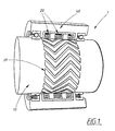
- a magneto-elastic torque sensor 1 is shown, which is arranged substantially concentrically in connection to a rotatable measuring shaft 10. Furthermore, the torque sensor is provided with at least one coil 20, preferably three coils, and at least one zone 30, preferably three zones.
- the zones may be constituted of parallel lines of, for instance, a suitable material on the shaft 10, e.g. a conductive material such as copper, and are displaced substantially 45° in relation to the length direction of the shaft.
- said coil is provided with an enclosing cover 40, for instance, of a magnetic material, and connections to the coils in order to measure a signal, for instance, voltage or current.
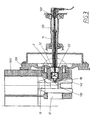
- a torque sensor 1 is shown, for instance the one which was shown in Fig. 1, which is mounted on or in connection to a rotatable shaft 12, for instance a crankshaft with appurtenant crank 16, which is provided with a substantially cylindrical recess 50, where at least one zone 30 (not shown in Fig. 2) on the sensor, preferably three zones, may be placed on an external envelope surface of a measuring shaft 10, attached in the recess 50.
- the zones may either be pressed into, plated, glued onto or in another way be mounted to an outer envelope surface of the measuring shaft.
- a transfer shaft 14, preferably a transmission shaft may further be combined in connection to said rotating shaft 12.
- the zones may be constituted of parallel lines of a conductive material on the shaft 10, preferably copper.
- the measuring shaft 10 is further concentrically surrounded by at least one, preferably three, stationary coils 20.
- One way of attaching the measuring shaft 10 to the rotatable shaft 12 is via a mechanical joint 60, for instance splines, and/or to provide a concentric aperture 70 through the measuring shaft 10 and the rotatable shaft 12 and to fix/lock these with a bolt 90 or a screw through the concentric aperture 70.
- the measuring shaft 10 may, for instance, be constituted of a magneto-elastic material.
- the rotating measuring shaft 10 may be enclosed by a yoke 80, whereby the construction of the yoke enables axial adjustment both before and after mounting, i.e. the yoke 80 may be trimmed in about the measuring shaft 10 and in this way the accuracy may be improved. If, furthermore, the measuring shaft 10 is fixed/locked axially to the rotating shaft 12, by means of said bolt 90 or screw, play and movement in the sensor are minimized.
- the rotating shaft passes through an engine block 100 with a parting line, i.e. cylinder block and bottom.
- the yoke 80 may be constituted by an inner and an outer cylindrical member, which are joined by a thin disc-shaped member.
- the coil may accordingly be attached to the inner cylindrical member of the yoke by means of press fitting, gluing etc. (see Fig. 2a).
- the yoke 80 may be mounted in a recess, which may be cylindrically designed in the engine block 100, at the same time as the yoke 80 is mounted about the rotating shaft 12.
- the outer cylindrical member of the yoke 80 is conveniently provided with a pair of circumferential cutting edges 110, as shown in Fig. 2a. When mounting, these edges 110 cut into the engine block 100 at the same time as they are partially deformed, which brings about effective centering and locking without transferring tensions to the bearing on the rotating shaft 12.
- bearings than plain bearings may, for instance, be constituted by ball bearings, roller bearings or self-aligning roller bearings. These other types of bearings may provide a more stable rotating shaft than when a plain bearing is used.
- the sealing between the yoke 80 and the engine block 100 may be constituted by sealing liquid, for instance Loctite (registered trademark), around the outer periphery of the outer cylinder and also a seal ring 200 around its inner periphery.
- sealing liquid for instance Loctite (registered trademark)
- Loctite registered trademark
- the measuring shaft 10 may be mounted in a similar way as described earlier, i.e. at the end of the crankshaft 12 via a splined coupling 60, locked with a bolt 90 and at the same time sealed with sealing liquid, for instance Loctite (registered trademark).
- the outer portion of the measuring shaft 10 is, for instance through welding, attached to a flywheel 120, preferably an easy-to-bend flywheel which allows certain movement of the flywheel 120 in an axial direction.
- the measuring shaft 10 is coated with magnetic material, and different zones 30 also possibly heat treated.
- crankshaft 12 may be coated directly with magnetic material and different zones 30, in which case the coil is divided in order to enable mounting.
- the purpose of the sealings is to prevent oil leakage from the engine into a transmission.
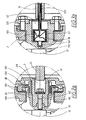
- a torque sensor 2 which is mounted on or in connection to a rotatable shaft 12, for instance a crankshaft, which is provided with a recess 52 which is substantially cylindrical, where at least one zone (not shown in Fig. 3), preferably three zones, on the sensor 2 are placed on the inner envelope surface of the recess 52, where said zone concentrically encloses at least one, preferably three stationary coils 22 which are journalled in the recess 52.
- the zones may either be pressed onto, glued, plated or mounted in another way on an outer envelope surface of a measuring shaft 18 fixed in the recess.
- a transfer shaft 14, preferably a transmission shaft, may furthermore be combined in connection to said rotating shaft 12.
- the zones may be constituted by parallel lines of a conductive material, preferably copper.
- a suitable material preferably a magneto-elastic material
- the zone is, furthermore, mounted inside a substantially cylindrical measuring body 18, which is situated in a recess in the end of the rotating shaft 12 and wherein said measuring body 18 is mounted essentially concentrically enclosing said coil/s 22 (see Fig. 3a).
- the connections to the journalled coil may be lead through a tube 150, which runs freely through a rotating transmission shaft, which is coaxial with the crankshaft 12. This tube 150 will be described in detail below.
- the coiling may be divided into a number of zones, which in themselves consist of previously known separate groups of coiling or coils 22 (see e.g. U.S. Patent No. 4,873,874), but for reasons of simplicity these are designated as a unit (“the coil”) in the following.
- the measuring body 18 may be connected to the recess 52 in the crankshaft 12 by means of being pressed or glued into position. It is also possible to plate the magneto-elastic material directly on the cylindrical surface of the recess 52.
- the position may, for instance, be chosen somewhere between the flywheel 120 and the last crank 16, for instance radially inside the crank bearing.
- the stationary coil 22 is provided with a pin 130 in the end facing the crankshaft, and is journalled by e.g. a flanged bearing 140 in the interior of the recess 52.
- the bearing may receive radial forces, but it is an advantage if it also can tolerate axial forces. It should, for instance, be possible to spring-load the coil 22 so that it follows axial movements of the crankshaft 12.
- the coil 22 may be built up by means of winding the wire around a cylindrical body, whereby the wires are placed in tracks and/or are moulded into or coated with a suitable material in order to fixate them.
- a tube 150 is mounted in the other end of the coil.
- the tube 150 may be mounted firmly or elastically in the end of the coil, or optionally be a through tube. In order to facilitate the mounting of the gearbox, the tube may also be mounted afterwards, with the aid of a press joint or some kind of quick-coupling.
- the coil 22 is journalled in the transfer shaft 14 in one end, and in the other end connected firmly or elastically to one end of the tube 150 which runs in a through hole in the transfer shaft 14, for instance a transmission shaft, which is coaxial with the crankshaft and is connected to this via a flywheel 120.
- the other end of the tube may be located inside a transmission casing 160 with an expander roll or the like and be sealed with e.g. an O-ring.
- the tube 150 may also be provided with an outer sealing gasket which contacts the hollow transfer shaft 14. If the gasket is placed close to the middle of the tube, it functions as a support and a bearing, so that any sudden jerks in the shaft do not affect the tube, i.e. so that the shaft and the tube do not come into contact with each other.
- the electrical connections run from the coil, through the tube 150, to sensor electronics, for instance driver and evaluation unit (see U.S. Patent No, 4,873,874).
- Still another way of mounting the coil 20 in the case when the rotating shaft 12 has a circumferential recess (not shown) with a certain extension in a radial direction, may be directly onto the shaft instead of a cylindrical recess.
- the coil 20 may, for instance, be placed in connection to a bearing.
- the zones on the measuring shaft may in that case be arranged directly on the rotating shaft.
Landscapes
- Physics & Mathematics (AREA)
- Electromagnetism (AREA)
- General Physics & Mathematics (AREA)
- Force Measurement Appropriate To Specific Purposes (AREA)
Description
- Fig. 1
- shows an embodiment of a magneto-elastic torque sensor;
- Fig. 2
- shows a first preferred embodiment of a torque sensor in accordance with the present invention;
- Fig. 2a
- shows an enlarged view of Fig. 2;
- Fig. 3
- shows a second preferred embodiment of a torque sensor in accordance with the present invention; and
- Fig. 3a
- shows an enlarged view of Fig. 3.
Claims (14)
- Method for mounting a torque sensor (1) in engines and driving transmissions, which is mounted substantially concentrically in connection to a rotatable shaft (12), where said torque sensor (1) is constituted by at least one stationary coil (20) and at least one zone (30) which is provided with parallel lines of a suitable material, preferably a conductive material such as copper, and where said at least one coil is placed in connection to said at least one zone and is provided with connections for measuring signals, where the rotatable shaft (12) is constituted by a crankshaft which is provided with a recess (50), whereby said at least one zone (30) is placed on an outer envelope surface of a measuring shaft (10), attached in the recess (50) and enclosed by said at least one stationary coil (20),
characterized in that said measuring shaft (10) and said recess (50) each is provided with an aperture (70), which jointly accept a bolt (90) or a screw through said apertures (70), in order to attach/lock the recess and the measuring shaft. - A method according to claim 1,
characterized in that the number of zones (30) is at least two and alternatingly displaced by substantially 45° in relation to the longitudinal direction of the measuring shaft (10). - Method for mounting a torque sensor (2) in engines and driving transmissions, which is mounted substantially concentrically in connection to a rotatable shaft (12), whereby the rotatable shaft (12) is constituted by a crankshaft which is provided with a peripheral recess (52), where said torque sensor (2) is constituted by at least one stationary coil (22) and at least one zone which is provided with parallel lines of a suitable material, preferably a conductive material such as copper, and where said at least one coil (22) is placed in said recess and in connection to said zone and is provided with connections for measuring signals, whereby said at least one zone is placed concentrically around said at least one stationary coil (22) inside the recess (52), characterized in that said at least one coil (22) is journalled in the interior of said recess and that the connections of said sensor are led through a tube (150), which runs freely through a rotating transfer shaft.
- A method according to claim 3,
characterized in that the number of zones is at least two, said zones being alternatingly displaced by substantially 45° in relation to the longitudinal direction of the recess. - A method according to claim 3 or 4,
characterized in that said zone is placed on the inner envelope surface of the recess (52), where said zone encloses the stationary coil (22) in the recess (52). - A method according to claim 3 or 4,
characterized in that a substantially cylindrical measuring body (18) is placed inside said recess and encloses said coil (22), whereby said zone is placed on the outer or inner envelope surface of the measuring body (18), where said zone encloses the stationary coil (22) in the recess (52). - Device for mounting a sensor (1) in engines and driving transmissions, which is arranged substantially concentrically in connection to a rotatable shaft (12), where said torque sensor (1) is constituted by at least one coil (20) and at least one zone (30) provided with parallel lines of a suitable material, preferably a conductive material such as copper, where said at least one coil (20) is provided with connections for measuring signals, whereby the rotatable shaft is constituted by a crankshaft which is provided with a recess (50), whereby said at least one zone (30) is arranged at an outer envelope surface of a measuring shaft (10) which is attached in the recess (50) and enclosed by said at least one stationary coil (20),
characterized in that said measuring shaft (10) and said recess (50) each is provided with an aperture (70), which accomodates a bolt (90) or a screw passing through said apertures (70), in order to attach/lock the recess and the measuring shaft. - A device according to claim 7,
characterized in that the recess (50) is substantially cylindrical. - A device according to claim 7 or 8,
characterized in that the number of zones (30) is at least two, said zones being displaced substantially 45° in relation to the longitudinal direction of the measuring shaft (10). - Device for mounting a sensor (2) in engines and driving transmissions, which is arranged substantially concentrically in connection to a rotatable shaft (12), whereby the rotatable shaft is constituted by a crankshaft and is provided with a peripheral recess (52), where said torque sensor (2) is constituted by at least one stationary coil (22), and at least one zone provided with parallel lines of a suitable material, preferably a conductive material such as copper, where said at least one coil (22) is arranged in said recess and in connection to said zone and provided with connections for measuring signals, whereby said at least one zone is placed concentrically around the at least one stationary coil (22) in the recess (52),
characterized in that said at least one coil (22) is journalled in the interior of said recess and that a tube (150) is arranged inside a transfer shaft (14), intended for the connections of said sensor (2). - A device according to claim 10,
characterized in that the recess (52) is substantially cylindrical. - A device according to claim 10 or 11,
characterized in that the number of zones is at least two, said zones being displaced substantially 45° in relation to the longitudinal direction of the recess. - A device according to claim 10, 11 or 12,
characterized in that said zone is arranged on the inner envelope surface of the recess (52), where said zone encloses the stationary coil (22) in the recess (52). - A device according to claim 10, 11 or 12,
characterized in that a substantially cylindrical measuring body (18) is arranged inside said recess and enclosing said coil (22), whereby said zone is arranged at the inner or outer envelope surface of the measuring body (18), where said zone encloses the stationary coil (22) in the recess (52).
Applications Claiming Priority (3)
| Application Number | Priority Date | Filing Date | Title |
|---|---|---|---|
| SE9601510A SE508383C2 (en) | 1996-04-19 | 1996-04-19 | Method and device for mounting a torque sensor in motors and drivelines. |
| SE9601510 | 1996-04-19 | ||
| PCT/SE1997/000647 WO1997040354A1 (en) | 1996-04-19 | 1997-04-17 | Torque transmitter |
Publications (2)
| Publication Number | Publication Date |
|---|---|
| EP0902886A1 EP0902886A1 (en) | 1999-03-24 |
| EP0902886B1 true EP0902886B1 (en) | 2005-01-26 |
Family
ID=20402278
Family Applications (1)
| Application Number | Title | Priority Date | Filing Date |
|---|---|---|---|
| EP97918468A Expired - Lifetime EP0902886B1 (en) | 1996-04-19 | 1997-04-17 | Mounting a torque sensor in a recess of a crankshaft |
Country Status (5)
| Country | Link |
|---|---|
| US (1) | US6260421B1 (en) |
| EP (1) | EP0902886B1 (en) |
| DE (1) | DE69732355T2 (en) |
| SE (1) | SE508383C2 (en) |
| WO (1) | WO1997040354A1 (en) |
Families Citing this family (19)
| Publication number | Priority date | Publication date | Assignee | Title |
|---|---|---|---|---|
| SE517710C2 (en) | 1999-12-14 | 2002-07-09 | Abb Ab | Magnetostrictive sensor for measuring torque and use of the sensor |
| US6698299B2 (en) * | 2001-05-05 | 2004-03-02 | Methode Electronics, Inc. | Magnetoelastic torque sensor |
| JP2003172430A (en) * | 2001-12-07 | 2003-06-20 | Jatco Ltd | Automatic transmission |
| KR100683927B1 (en) * | 2004-12-31 | 2007-02-15 | 재단법인서울대학교산학협력재단 | Magnetostrictive transducer using tail patch and elastic wave measuring device using the same |
| DE102009008074A1 (en) * | 2009-02-10 | 2010-08-12 | Siemens Aktiengesellschaft | Measuring arrangement and use for detecting the torque |
| EP2420803A1 (en) | 2010-08-13 | 2012-02-22 | BALLUFF GmbH | Device for recording the torsion angle of a shaft and/or the torque of a shaft and method for operating the device |
| WO2012107006A1 (en) | 2011-02-09 | 2012-08-16 | Balluff Gmbh | Method for detecting the torsion angle of a shaft and/or of a torque occurring on the shaft and implementation of the method |
| US9383273B2 (en) | 2011-05-24 | 2016-07-05 | Ford Global Technologies, Llc | Magnetic torque sensor packaging for automatic transmissions |
| US8844379B2 (en) | 2011-05-24 | 2014-09-30 | Ford Global Technologies, Llc | Transmissions with electronics interface assembly for torque sensor |
| US9285282B2 (en) | 2013-02-20 | 2016-03-15 | Ford Global Technologies, Llc | Magnetic sensor packaging for transmissions |
| US9382840B2 (en) | 2013-03-11 | 2016-07-05 | Teledyne Instruments, Inc. | Engine crankshaft torque sensor |
| US9074953B2 (en) * | 2013-04-29 | 2015-07-07 | Ford Global Technologies, Llc | Sensor packaging at output side of front wheel drive (FWD) transmissions |
| DE102013019955A1 (en) | 2013-11-27 | 2015-06-11 | Avl List Gmbh | Internal combustion engine |
| DE202014002597U1 (en) | 2014-03-26 | 2014-06-12 | Balluff Gmbh | Magnetic ring and position sensor |
| WO2016057263A1 (en) * | 2014-10-09 | 2016-04-14 | Borgwarner Inc. | Clutch with integrated temperature sensor |
| US9791034B1 (en) * | 2016-04-14 | 2017-10-17 | Ford Global Technologies, Llc | Torque sensor packaging for automatic transmissions |
| GB2565305A (en) * | 2017-08-08 | 2019-02-13 | Cambridge Touch Tech Ltd | Device for processing signals from a pressure-sensing touch panel |
| US10371199B2 (en) | 2017-11-22 | 2019-08-06 | Teledyne Lecroy, Inc. | Engine crankshaft torque sensor cartridge |
| JP2020197496A (en) * | 2019-06-05 | 2020-12-10 | 日本精工株式会社 | Torque sensor |
Family Cites Families (11)
| Publication number | Priority date | Publication date | Assignee | Title |
|---|---|---|---|---|
| US3740999A (en) * | 1972-04-13 | 1973-06-26 | Stanley Works | Power tool having stall torque calibrating unit |
| SE452509B (en) * | 1983-05-26 | 1987-11-30 | Asea Ab | Magnetoelastic torque-sensing transducer |
| US4712433A (en) * | 1985-10-18 | 1987-12-15 | Aisin Seiki Kabushiki Kaisha | Torque sensor for automotive power steering systems |
| JPS63210740A (en) * | 1987-02-27 | 1988-09-01 | Honda Motor Co Ltd | torque sensor |
| US4887461A (en) | 1987-06-26 | 1989-12-19 | Nissan Motor Co., Ltd | Magnetostriction type torque sensor |
| SE460154B (en) | 1987-09-28 | 1989-09-11 | Asea Ab | MAGNETOELASTIC Torque Sensor |
| DE3918862A1 (en) * | 1989-06-09 | 1991-01-10 | Danfoss As | TORQUE MEASURING DEVICE |
| SE9200477L (en) * | 1992-02-18 | 1993-08-16 | Asea Brown Boveri | MECHANICAL CONNECTION BETWEEN A DRIVE CELL AND A LOAD OBJECTED FOR APPLICATION OF A TORQUE MEASURING DEVICE |
| US5375476A (en) * | 1993-09-30 | 1994-12-27 | Wetherford U.S., Inc. | Stuck pipe locator system |
| SE508734C2 (en) * | 1994-03-30 | 1998-11-02 | Asea Brown Boveri | Magnetoelastic non-contact torque sensor |
| SE9402158L (en) * | 1994-06-20 | 1995-12-21 | Asea Brown Boveri | Mechanical connection between drive source and load objects designed for application of torque, speed or angular position sensors or a combination of these |
-
1996
- 1996-04-19 SE SE9601510A patent/SE508383C2/en not_active IP Right Cessation
-
1997
- 1997-04-17 US US09/171,436 patent/US6260421B1/en not_active Expired - Fee Related
- 1997-04-17 WO PCT/SE1997/000647 patent/WO1997040354A1/en not_active Ceased
- 1997-04-17 DE DE69732355T patent/DE69732355T2/en not_active Expired - Fee Related
- 1997-04-17 EP EP97918468A patent/EP0902886B1/en not_active Expired - Lifetime
Also Published As
| Publication number | Publication date |
|---|---|
| DE69732355T2 (en) | 2006-01-12 |
| EP0902886A1 (en) | 1999-03-24 |
| SE9601510D0 (en) | 1996-04-19 |
| US6260421B1 (en) | 2001-07-17 |
| DE69732355D1 (en) | 2005-03-03 |
| SE9601510L (en) | 1997-10-20 |
| WO1997040354A1 (en) | 1997-10-30 |
| SE508383C2 (en) | 1998-09-28 |
Similar Documents
| Publication | Publication Date | Title |
|---|---|---|
| EP0902886B1 (en) | Mounting a torque sensor in a recess of a crankshaft | |
| US6516508B1 (en) | Magnetoelastic non-compliant torque sensor and method of producing same | |
| WO2006122269A1 (en) | Bearing assembly with integrated sensor system | |
| US4589290A (en) | Torque sensor | |
| US4977782A (en) | Device for measuring the torque of a valve moved by an actuator | |
| US6003872A (en) | Method of monitoring a seal for correct operation, and monitoring device for carrying out the method | |
| US9618407B2 (en) | Magnetic sensor packaging for transmissions | |
| US3377849A (en) | Torque sensing apparatus | |
| CN101046419B (en) | Torque detecting apparatus, and method for assembling torque detecting apparatus | |
| US20090293642A1 (en) | Arrangement for the non-contact measurement of torque | |
| CN102607748B (en) | There is the torque sensor system of integrated electric connector | |
| US3823608A (en) | Torque transducer | |
| EP1875183A1 (en) | Torqueshaft magnetic field measurement system | |
| US5018393A (en) | Device for determining torque transmitted in a shaft | |
| EP0814328B1 (en) | A device for measuring compressive forces | |
| JP7647328B2 (en) | Torque Measuring Device | |
| US5913251A (en) | Rotating shaft incorporating a device for measuring torque | |
| US20220337118A1 (en) | Electric actuator | |
| US5374134A (en) | Mechanical coupling for torque transducer | |
| US2353814A (en) | Torque indicator | |
| US6705761B1 (en) | Bearing with integral transformer | |
| KR20210142181A (en) | Transmission housing and differential | |
| US4951502A (en) | Pressure probe | |
| EP1937989B1 (en) | Bearing assembly with a strain sensor | |
| SE514894C2 (en) | Engine shaft torque sensor and mounting method |
Legal Events
| Date | Code | Title | Description |
|---|---|---|---|
| PUAI | Public reference made under article 153(3) epc to a published international application that has entered the european phase |
Free format text: ORIGINAL CODE: 0009012 |
|
| 17P | Request for examination filed |
Effective date: 19981001 |
|
| AK | Designated contracting states |
Kind code of ref document: A1 Designated state(s): DE FR GB IT |
|
| 17Q | First examination report despatched |
Effective date: 20030429 |
|
| GRAP | Despatch of communication of intention to grant a patent |
Free format text: ORIGINAL CODE: EPIDOSNIGR1 |
|
| RTI1 | Title (correction) |
Free format text: MOUNTING A TORQUE SENSOR IN A RECESS OF A CRANKSHAFT |
|
| GRAS | Grant fee paid |
Free format text: ORIGINAL CODE: EPIDOSNIGR3 |
|
| GRAA | (expected) grant |
Free format text: ORIGINAL CODE: 0009210 |
|
| RAP1 | Party data changed (applicant data changed or rights of an application transferred) |
Owner name: VOLVO CAR CORPORATION |
|
| AK | Designated contracting states |
Kind code of ref document: B1 Designated state(s): DE FR GB IT |
|
| PG25 | Lapsed in a contracting state [announced via postgrant information from national office to epo] |
Ref country code: IT Free format text: LAPSE BECAUSE OF FAILURE TO SUBMIT A TRANSLATION OF THE DESCRIPTION OR TO PAY THE FEE WITHIN THE PRE;WARNING: LAPSES OF ITALIAN PATENTS WITH EFFECTIVE DATE BEFORE 2007 MAY HAVE OCCURRED AT ANY TIME BEFORE 2007. THE CORRECT EFFECTIVE DATE MAY BE DIFFERENT FROM THE ONE RECORDED.SCRIBED TIME-LIMIT Effective date: 20050126 Ref country code: FR Free format text: LAPSE BECAUSE OF FAILURE TO SUBMIT A TRANSLATION OF THE DESCRIPTION OR TO PAY THE FEE WITHIN THE PRESCRIBED TIME-LIMIT Effective date: 20050126 |
|
| REG | Reference to a national code |
Ref country code: GB Ref legal event code: FG4D |
|
| REF | Corresponds to: |
Ref document number: 69732355 Country of ref document: DE Date of ref document: 20050303 Kind code of ref document: P |
|
| PLBE | No opposition filed within time limit |
Free format text: ORIGINAL CODE: 0009261 |
|
| STAA | Information on the status of an ep patent application or granted ep patent |
Free format text: STATUS: NO OPPOSITION FILED WITHIN TIME LIMIT |
|
| 26N | No opposition filed |
Effective date: 20051027 |
|
| EN | Fr: translation not filed | ||
| PGFP | Annual fee paid to national office [announced via postgrant information from national office to epo] |
Ref country code: GB Payment date: 20080317 Year of fee payment: 12 |
|
| PGFP | Annual fee paid to national office [announced via postgrant information from national office to epo] |
Ref country code: DE Payment date: 20080430 Year of fee payment: 12 |
|
| GBPC | Gb: european patent ceased through non-payment of renewal fee |
Effective date: 20090417 |
|
| PG25 | Lapsed in a contracting state [announced via postgrant information from national office to epo] |
Ref country code: DE Free format text: LAPSE BECAUSE OF NON-PAYMENT OF DUE FEES Effective date: 20091103 |
|
| PG25 | Lapsed in a contracting state [announced via postgrant information from national office to epo] |
Ref country code: GB Free format text: LAPSE BECAUSE OF NON-PAYMENT OF DUE FEES Effective date: 20090417 |