EP0902447A2 - Auxiliary switch assembly - Google Patents
Auxiliary switch assembly Download PDFInfo
- Publication number
- EP0902447A2 EP0902447A2 EP98108571A EP98108571A EP0902447A2 EP 0902447 A2 EP0902447 A2 EP 0902447A2 EP 98108571 A EP98108571 A EP 98108571A EP 98108571 A EP98108571 A EP 98108571A EP 0902447 A2 EP0902447 A2 EP 0902447A2
- Authority
- EP
- European Patent Office
- Prior art keywords
- contact
- leaf spring
- auxiliary switch
- slide
- spring band
- Prior art date
- Legal status (The legal status is an assumption and is not a legal conclusion. Google has not performed a legal analysis and makes no representation as to the accuracy of the status listed.)
- Granted
Links
- 238000006073 displacement reaction Methods 0.000 claims 1
- 239000000969 carrier Substances 0.000 abstract 1
- 230000015572 biosynthetic process Effects 0.000 description 1
- 230000006835 compression Effects 0.000 description 1
- 238000007906 compression Methods 0.000 description 1
- 230000008878 coupling Effects 0.000 description 1
- 238000010168 coupling process Methods 0.000 description 1
- 238000005859 coupling reaction Methods 0.000 description 1
- 230000005520 electrodynamics Effects 0.000 description 1
- 238000009434 installation Methods 0.000 description 1
- 230000036316 preload Effects 0.000 description 1
- 238000000926 separation method Methods 0.000 description 1
Images

Classifications
-
- H—ELECTRICITY
- H01—ELECTRIC ELEMENTS
- H01H—ELECTRIC SWITCHES; RELAYS; SELECTORS; EMERGENCY PROTECTIVE DEVICES
- H01H9/00—Details of switching devices, not covered by groups H01H1/00 - H01H7/00
- H01H9/0066—Auxiliary contact devices
-
- H—ELECTRICITY
- H01—ELECTRIC ELEMENTS
- H01H—ELECTRIC SWITCHES; RELAYS; SELECTORS; EMERGENCY PROTECTIVE DEVICES
- H01H1/00—Contacts
- H01H1/12—Contacts characterised by the manner in which co-operating contacts engage
- H01H1/14—Contacts characterised by the manner in which co-operating contacts engage by abutting
- H01H1/20—Bridging contacts
-
- H—ELECTRICITY
- H01—ELECTRIC ELEMENTS
- H01H—ELECTRIC SWITCHES; RELAYS; SELECTORS; EMERGENCY PROTECTIVE DEVICES
- H01H11/00—Apparatus or processes specially adapted for the manufacture of electric switches
- H01H11/0006—Apparatus or processes specially adapted for the manufacture of electric switches for converting electric switches
- H01H11/0012—Apparatus or processes specially adapted for the manufacture of electric switches for converting electric switches for converting normally open to normally closed switches and vice versa
-
- H—ELECTRICITY
- H01—ELECTRIC ELEMENTS
- H01H—ELECTRIC SWITCHES; RELAYS; SELECTORS; EMERGENCY PROTECTIVE DEVICES
- H01H15/00—Switches having rectilinearly-movable operating part or parts adapted for actuation in opposite directions, e.g. slide switch
- H01H15/02—Details
- H01H15/06—Movable parts; Contacts mounted thereon
- H01H15/10—Operating parts
- H01H15/102—Operating parts comprising cam devices
- H01H15/105—Adjustable cams
Definitions
- the present invention relates to an auxiliary switch arrangement with at least two fixed contact pieces fastened in a housing and with at least one with the fixed contact pieces by moving one with linear cams provided, operated by a switching device slide in and out of engagement bringable, in the closing direction spring-loaded contact bridge, which is in the disconnected position lifted off the fixed contact pieces by the cams of the slide is.
- EP-B1-0347999 is an auxiliary switch arrangement of the type mentioned above.
- This auxiliary switch arrangement at least two fixed contact pieces are arranged in a housing.
- Each two fixed contact pieces are connected by a movable contact bridge connected to each other in the switch-on position.
- the contact bridge is as a bar at one end of a T-shaped, with the other end pivotable in the housing mounted pivot lever attached.
- the swivel lever is in the closing direction the contact pieces are spring-loaded by a coil spring.
- In the housing is a slider provided with linear cams slidably mounted. The slide is usually coupled to an electrical switching device and moved with the movable contact pieces of the switching device.
- the object of the present invention is to provide an auxiliary switch arrangement create that has relatively few items for an automatic Installation is suitable and therefore economically advantageous and for all existing electrical loads maintain their functionality.
- the task is solved in that the contact bridge at one end a U-shaped leaf spring band transverse to the longitudinal direction of the leaf spring band molded in one piece and the other, free end of the U-shaped curved leaf spring band is fixed in the housing, the leaf spring band in the contacting closing position of the contact bridge by the amount of the contact pressure is biased.
- This arrangement there is the movable one Contact bridge and that the contact pressure for the moving contact pieces
- One-piece leaf spring band attached to the case is.
- This arrangement is suitable for automatic assembly and economically advantageous.
- the fact that the leaf spring band is not live the current passed through the auxiliary switch affects the properties the auxiliary switch arrangement is not.
- the leaf spring band advantageously projects between the two on the two End areas of the contact bridge attached movable contact pieces the contact bridge, with the protruding part becoming one with the cams the slide interacting slide bracket is shaped.
- the one from the material The leaf spring band shaped slide bracket completes the functions of the one-piece leaf spring band.
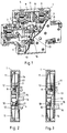
- the auxiliary switch arrangement has a housing 1 which the arrangement closes to the outside. In the housing 1 are visible in Fig.1 Fixed contact pieces 2, 3, 4 attached. The fixed contact pieces 2, 3, 4 are with the terminals 5, 6, 7, 8 of the auxiliary switch in an electrically conductive connection. The fixed contact pieces 2 and 3 and 4 and not in Fig.1 visible, are in the switched-on position with the contact bridges 9, 10 with each other connected.
- the contact bridges 9, 10 are U-shaped at one end bent leaf spring bands 11 are formed, as in Figures 4, 5 and 6th can be seen. The other ends 12 of the leaf spring bands 11 are in the housing 1 attached.
- the leaf spring strips 11 bring in the contact-making closed position the contact bridges 9, 10 on the contact pressure, because they by the amount of Contact pressure are biased.
- the leaf spring strips 11 protrude between the two end regions of the contact bridges 9, 10 beyond the contact bridges 9, 10, the outstanding ones Parts are formed into sliding brackets 13.
- This slide bracket 13 serve the Contact bridges 9, 10 to lift off the fixed contact pieces 2, 3, 4 and the Bring the auxiliary switch to the off position.
- the auxiliary switch assembly is equipped with a slide 14 which in Housing 1 is held and guided longitudinally.
- This slider 14 is provided with a linear cam 15. 2 shows the slide 14 in the upper position. In this position it is clearly visible that the cam 15 underneath the slide bracket 13 of the upper contact bridge 9 is pushed. This contact bridge 9 is thus lifted off the fixed contact pieces 2 and 3, the connection between terminals 5 and 6 is interrupted.
- the lower Slide bracket 13 is free, the contact bridge 10 is with the fixed contact pieces 4th in connection, the connection terminals 7 and 8 are electrically connected.
- the one-piece leaf spring band 11 is alone in FIGS. 4, 5 and 6 shown. In Figure 4 and also in Figure 6 are attached to the leaf spring band 11 movable contact pieces 17 particularly visible.
- FIG. 7 shows the slide 14 with differently arranged Cams 15, 18, 19, 20, 21. Due to the different designs of the cams 15, 18, 19, 20, 21, the closing and / or opening contacts as required to get voted.
- the cams 18, 19 shown in FIG. 7 actuate two Opener contacts, the cams 20, 21 visible in FIG. 8 have two make contacts.
- the cams 15 shown in FIG. 9 serve to actuate an opener and a make contact.
Landscapes
- Physics & Mathematics (AREA)
- Electromagnetism (AREA)
- Slide Switches (AREA)
- Push-Button Switches (AREA)
- Oscillators With Electromechanical Resonators (AREA)
- Supplying Of Containers To The Packaging Station (AREA)
- Control Of Motors That Do Not Use Commutators (AREA)
- Control Of Eletrric Generators (AREA)
- Vehicle Body Suspensions (AREA)
- Coupling Device And Connection With Printed Circuit (AREA)
- Measurement And Recording Of Electrical Phenomena And Electrical Characteristics Of The Living Body (AREA)
- Contacts (AREA)
Abstract
Description
Die vorliegende Erfindung betrifft eine Hilfsschalteranordnung mit mindestens zwei in einem Gehäuse befestigten Festkontaktstücken und mit mindestens einer mit den Festkontaktstücken durch Verschiebung eines mit linearen Nocken versehenen, durch ein Schaltgerät betätigbaren Schiebers in und ausser Eingriff bringbaren, in Schliessrichtung federbelasteten Kontaktbrücke, die in der Trennstellung durch die Nocken des Schiebers von den Festkontaktstücken abgehoben ist.The present invention relates to an auxiliary switch arrangement with at least two fixed contact pieces fastened in a housing and with at least one with the fixed contact pieces by moving one with linear cams provided, operated by a switching device slide in and out of engagement bringable, in the closing direction spring-loaded contact bridge, which is in the disconnected position lifted off the fixed contact pieces by the cams of the slide is.
Aus der europäischen Patentschrift, EP-B1-0347999 ist eine Hilfschalteranordnung der eingangs erwähnten Art bekannt. Bei dieser Hilfsschalteranordnung sind mindestens zwei Festkontaktstücke in einem Gehäuse angeordnet. Jeweils zwei Festkontaktstücke werden dabei durch eine bewegliche Kontaktbrücke in der Einschaltstellung miteinander verbunden. Die Kontaktbrücke ist als Balken am einen Ende eines T-förmigen, mit dem Anderen Ende im Gehäuse schwenkbar gelagerten Schwenkhebels angebracht. Der Schwenkhebel ist in Schliessrichtung der Kontaktstücke durch eine Schraubenfeder federbelastet. Im Gehäuse ist ein mit linearen Nocken versehener Schieber verschiebbar gelagert. Der Schieber wird in der Regel an einem elektrischen Schaltgerät angekoppelt und mit den beweglichen Kontaktstücken des Schaltgerätes mitbewegt. Die am Schieber vorhandenen linearen Nocken greifen an den Schwenkhebeln an und bewegen diese mit den Kontaktbrücken gegen die Federwirkung. In der Ausschaltstellung des Hilfsschalters heben die Nocken die Kontaktbrücken von den Festkontaktstücken ab. In der Einschaltstellung bringt die Schraubenfeder den Kontaktdruck auf die Kontaktbrücke auf. Ein erster Nachteil dieser Hilfsschalteranordnung besteht darin, dass der Schwenkhebel im Gehäuse schwenkbar gelagert werden muss, was mit der Ausbildung von Lagerstellen verbunden ist. Die Montage der Schwenkhebel in Verbindung mit der Schraubenfeder sind für eine automatische Montage nicht geeignet. In einer weiteren, ähnlich aufgebauten Hilfsschalteranordnung nach der Patentschrift, US-A-3016440 erhöht eine zusätzliche Druckfeder die Teilenzahl, den Montageaufwand und die Betätigungskraft, die von den Betätigungsorganen des elektrischen Schaltgerätes aufgebracht werden muss. Ausserdem kann es zu Anpassungsproblemen bei der Kopplung an unterschiedliche Schaltgeräte mit verschiedenen Hüben kommen. From the European patent specification, EP-B1-0347999 is an auxiliary switch arrangement of the type mentioned above. With this auxiliary switch arrangement at least two fixed contact pieces are arranged in a housing. Each two fixed contact pieces are connected by a movable contact bridge connected to each other in the switch-on position. The contact bridge is as a bar at one end of a T-shaped, with the other end pivotable in the housing mounted pivot lever attached. The swivel lever is in the closing direction the contact pieces are spring-loaded by a coil spring. In the housing is a slider provided with linear cams slidably mounted. The slide is usually coupled to an electrical switching device and moved with the movable contact pieces of the switching device. The most Linear cams of sliders engage the swivel levers and move them with the contact bridges against the spring action. In the off position of the auxiliary switch, the cams lift the contact bridges from the Fixed contact pieces. In the on position, the coil spring brings the Contact pressure on the contact bridge. A first disadvantage of this auxiliary switch arrangement is that the pivot lever in the housing can be pivoted must be stored, which is associated with the formation of storage locations. The assembly of the swivel levers in connection with the coil spring are for automatic assembly is not suitable. In another, similar one Auxiliary switch assembly according to the patent, US-A-3016440 increases one additional compression spring the number of parts, the assembly effort and the actuation force, applied by the actuators of the electrical switching device must become. In addition, there may be adjustment problems with the Coupling to different switchgear come with different strokes.
Aus der US-A-3675168 ist ein Schaltgerät mit einem in einem Gehäuse untergebrachten Festkontaktstück und mit einem am einen Ende eines U-förmig gegebogenen Blattfederbandes angebrachten beweglichen Kontaktstück bekannt. Das andere, freie Ende des Blattfederbandes ist am Gehäuse befestigt und dient als elektrische Anschlusstelle. Das am einen Ende des Blattfederbandes liegende bewegliche Kontaktstück wird durch einen Schieber über einen von der Kontaktstelle entfernten Nockenanordnung mit dem Festkontaktstück in und ausser Eingriff gebracht. Insbesondere bei Ueberstrom können die zwischen den parallelen Teilen des U-förmigen Blattfederbandes auftretenden elektrodynamischen Kräfte zu Schwingungen und als Folge zu Kontakttrennungen führen. Ausserdem wird das stromführende U-förmige Blattfederband durch den durchfliessenden Stom geheizt, was insbesondere bei Ueberströmen zu Beeinflussung der Federcharakteristik des Blattfederbandes führen kann.From US-A-3675168 is a switching device with a housed in a housing Fixed contact piece and with one bent at one end of a U-shape Leaf spring band attached movable contact piece known. The other, free end of the leaf spring band is attached to the housing and serves as an electrical connection point. The one lying at one end of the leaf spring band Movable contact piece is moved by a slide via one of the contact point removed cam arrangement with the fixed contact piece in and out Brought in. In the event of overcurrent in particular, those between the parallel Parts of the U-shaped leaf spring band occurring electrodynamic Forces cause vibrations and, as a result, contact separation. Furthermore is the current-carrying U-shaped leaf spring band through the flowing Electrically heated, which affects the spring characteristic, particularly in the case of overcurrents of the leaf spring band can lead.
Aufgabe der vorliegenden Erfindung ist es, eine Hilfsschalteranordnung zu schaffen, die verhältnismässig wenige Einzelteile aufweist, für eine automatische Montage geeignet und somit wirtschaftlich vorteilhaft ist und bei allen vorkommanden Strombelastungen ihre Funktionstüchtigkeit beibehält.The object of the present invention is to provide an auxiliary switch arrangement create that has relatively few items for an automatic Installation is suitable and therefore economically advantageous and for all existing electrical loads maintain their functionality.
Die gestellte Aufgabe ist dadurch gelöst, dass die Kontaktbrücke am einen Ende eines U-förmig gebogenen Blattfederbandes quer zur Längsrichtung des Blattfederbandes einstückig angeformt und das andere, freie Ende des U-förmig gebogenen Blattfederbandes im Gehäuse befestigt ist, wobei das Blattfederband in kontaktgebender Schliesstellung der Kontaktbrücke um den Betrag des Kontaktdruckes vorgespannt ist. Bei dieser Anordnung besteht die bewegliche Kontaktbrücke und das den Kontaktdruck für die beweglichen Kontaktstücke aufbringende Blattfederband aus einem einzigen Stück, das am Gehäuse befestigt ist. Diese Anordnung ist für eine automatische Montage geeignet und wirtschaftlich vorteilhaft. Dadurch, dass das Blattfederband nicht stromführend ist, beeinflusst der durch den Hilfsschalter geführte Strom die Eigenschaften der Hilfsschalteranordnung nicht.The task is solved in that the contact bridge at one end a U-shaped leaf spring band transverse to the longitudinal direction of the leaf spring band molded in one piece and the other, free end of the U-shaped curved leaf spring band is fixed in the housing, the leaf spring band in the contacting closing position of the contact bridge by the amount of the contact pressure is biased. With this arrangement there is the movable one Contact bridge and that the contact pressure for the moving contact pieces One-piece leaf spring band attached to the case is. This arrangement is suitable for automatic assembly and economically advantageous. The fact that the leaf spring band is not live the current passed through the auxiliary switch affects the properties the auxiliary switch arrangement is not.
Das Blattfederband ragt vorteilhafterweise zwischen den beiden auf den beiden Endbereichen der Kontaktbrücke angebrachten beweglichen Kontaktstücken über die Kontaktbrücke hinaus, wobei der überragende Teil zu einem mit den Nocken des Schiebers zusammenwirkenden Gleitbügel geformt ist. Der aus dem Material des Blattfederbandes geformte Gleitbügel vervollständigt die Funktionen des einstückigen Blattfederbandes. The leaf spring band advantageously projects between the two on the two End areas of the contact bridge attached movable contact pieces the contact bridge, with the protruding part becoming one with the cams the slide interacting slide bracket is shaped. The one from the material The leaf spring band shaped slide bracket completes the functions of the one-piece leaf spring band.
Mit Vorteil sind mehrere Kontaktbrücken und ein gemeinsamer Schieber mit mehreren zu jeder Kontaktbrücke zugeordneten Nocken vorgesehen. Mit mehreren Kontaktbrücken und mit einem mit entsprechend angeordneten Nocken versehenen Schieber können nach Bedarf beliebige Oeffner- und/oder Schliesskontakte zur Verfügung gestellt werden.It is advantageous to have several contact bridges and a common slide several cams assigned to each contact bridge are provided. With several Contact bridges and with one with appropriately arranged cams provided slider can open and / or make contacts as required to provide.
Im folgenden wird anhand der beiliegenden Zeichnungen ein Ausführungsbeispiel der Erfindung näher beschrieben. Es zeigen:
- Fig.1
- eine Hilfsschalteranordnung in perspektivischen Darstellung, teilweise im Schnitt,
- Fig.2
- von der Seite im Schnitt mit einem Schieber in der oberen Stellung,
- Fig.3
- in der unteren Stellung,
- Fig.4
- ein Blattfederband in perspektivischer Darstellung,
- Fig.5
- in Seitenriss,
- Fig.6
- in Aufriss,
- Fig.7 bis 9
- einen Schieber mit unterschiedlich angeordneten Nocken, in perspektivischer Darstellung.
- Fig. 1
- an auxiliary switch arrangement in perspective, partially in section,
- Fig. 2
- cut from the side with a slider in the upper position,
- Fig. 3
- in the lower position,
- Fig. 4
- a leaf spring band in perspective,
- Fig. 5
- in side view,
- Fig. 6
- in elevation,
- Fig. 7 to 9
- a slide with differently arranged cams, in perspective.
Die Fig.1 zeigt eine Hilfsschalteranordnung in perspektivischer Darstellung,
teilweise im Schnitt. Die Hilfsschalteranordnung weist ein Gehäuse 1 auf, das
die Anordnung nach aussen abschliesst. Im Gehäuse 1 sind in Fig.1 sichtbare
Festkontaktstücke 2, 3, 4 befestigt. Die Festkontaktstücke 2, 3, 4 stehen mit
den Anschlussklemmen 5, 6, 7, 8 des Hilfsschalters in elektrisch leitender
verbindung. Die Festkontaktstücke 2 und 3 sowie 4 und das in Fig.1 nicht
sichtbare, werden in der Einschaltstellung mit den Kontaktbrücken 9, 10 miteinander
verbunden. Die Kontaktbrücken 9, 10 sind am einen Ende von U-förmig
gebogenen Blattfederbändern 11 angeformt, wie in den Figuren 4, 5 und 6
ersichtlich ist. Die anderen Enden 12 der Blattfederbändern 11 sind im Gehäuse
1 befestigt. Die Blattfederbänder 11 bringen in kontaktgebender Schliesstellung
der Kontaktbrücken 9, 10 den Kontaktdruck auf, weil sie um den Betrag des
Kontaktdruckes vorgespannt sind.1 shows a perspective view of an auxiliary switch arrangement,
partly in the cut. The auxiliary switch arrangement has a
Die Blattfederbänder 11 ragen zwischen den beiden Endbereichen der Kontaktbrücken
9, 10 über die Kontaktbrücken 9, 10 hinaus, wobei die überragenden
Teile zu Gleitbügeln 13 geformt sind. Diese Gleitbügel 13 dienen dazu, die
Kontaktbrücken 9, 10 von den Festkontaktstücken 2, 3, 4 abzuheben und den
Hilfsschalter so in die Ausschaltstellung zu bringen. The leaf spring strips 11 protrude between the two end regions of the contact bridges
9, 10 beyond the contact bridges 9, 10, the outstanding ones
Parts are formed into sliding
Die Hilfsschalteranordnung ist mit einem Schieber 14 ausgerüstet, der im
Gehäuse 1 längsverschiebbar gehalten und geführt ist. Dieser Schieber 14 ist
mit einem linearen Nocken 15 versehen. Fig.2 zeigt den Schieber 14 in der
oberen Stellung. In dieser Stellung ist gut sichtbar, dass der Nocken 15 unter
den Gleitbügel 13 der oberen Kontaktbrücke 9 geschoben ist. Diese Kontaktbrücke
9 ist somit von den Festkontaktstücken 2 und 3 abgehoben, die Verbindung
zwischen den Anschlussklemmen 5 und 6 ist unterbrochen. Der untere
Gleitbügel 13 ist frei, die Kontaktbrücke 10 steht mit den Festkontaktstücken 4
in Verbindung, die Anschlussklemmen 7 und 8 sind elektrisch verbunden.The auxiliary switch assembly is equipped with a
Fig.3 zeigt die Hilfsschalteranordnung mit nach unten geschobenem Schieber 14.
In dieser Stellung sind die Festkontaktstücke 2, 3 verbunden, weil der Gleitbügel
13 des oberen Blattfederbandes 11 frei ist und die Kontaktbrücke 9 auf die
Festkontakstücke 2, 3 aufliegen kann. Der Kontaktdruck ergibt sich aus der
Vorspannung des Blattfederbandes 11. Der Schieber 14 ist mit einem Fortsatz
16 versehen, der durch ein nicht dargestelltes elektrisches Schaltgerät verschoben
werden kann.3 shows the auxiliary switch arrangement with the
Das einstückige Blattfederband 11 ist in den Figuren 4, 5 und 6 allein
dargestellt. In Fig.4 und auch in Fig.6 sind die am Blattfederband 11 befestigten
beweglichen Kontaktstücke 17 besonders gut sichbar.The one-piece
Die Figuren 7, 8 und 9 zeigen den Schieber 14 mit unterschiedlich angeordneten
Nocken 15, 18, 19, 20, 21. Durch die unterschiedlichen Ausbildungen der Nocken
15, 18, 19, 20, 21 können die Schliess- und/oder Oeffnerkontakte nach Bedarf
gewählt werden. Die in Fig.7 dargestellten Nocken 18, 19 betätigen zwei
Oeffnerkontakte, die in Fig.8 sichtbaren Nocken 20, 21 zwei Schliesskontakte.
Die in Fig.9 gezeigten Nocken 15 dienen zur Betätigung von einem Oeffner- und
einem Schliesskontakt.Figures 7, 8 and 9 show the
Claims (3)
Applications Claiming Priority (3)
| Application Number | Priority Date | Filing Date | Title |
|---|---|---|---|
| CH211397 | 1997-09-09 | ||
| CH2113/97 | 1997-09-09 | ||
| CH211397 | 1997-09-09 |
Publications (3)
| Publication Number | Publication Date |
|---|---|
| EP0902447A2 true EP0902447A2 (en) | 1999-03-17 |
| EP0902447A3 EP0902447A3 (en) | 2000-01-12 |
| EP0902447B1 EP0902447B1 (en) | 2003-06-25 |
Family
ID=4226185
Family Applications (1)
| Application Number | Title | Priority Date | Filing Date |
|---|---|---|---|
| EP98108571A Expired - Lifetime EP0902447B1 (en) | 1997-09-09 | 1998-05-12 | Auxiliary switch assembly |
Country Status (7)
| Country | Link |
|---|---|
| US (1) | US5927485A (en) |
| EP (1) | EP0902447B1 (en) |
| AT (1) | ATE243883T1 (en) |
| DE (1) | DE59808798D1 (en) |
| DK (1) | DK0902447T3 (en) |
| ES (1) | ES2196423T3 (en) |
| PT (1) | PT902447E (en) |
Families Citing this family (3)
| Publication number | Priority date | Publication date | Assignee | Title |
|---|---|---|---|---|
| JP4546639B2 (en) * | 2000-12-06 | 2010-09-15 | ナイルス株式会社 | Inhibitor switch |
| US6534737B1 (en) | 2002-02-19 | 2003-03-18 | Onan Corporation | Contact closing speed limiter for a transfer switch |
| CN111180224B (en) * | 2019-09-26 | 2021-11-09 | 胡建强 | High-reliability fire-cut-off limiter |
Family Cites Families (11)
| Publication number | Priority date | Publication date | Assignee | Title |
|---|---|---|---|---|
| US3249725A (en) * | 1963-05-23 | 1966-05-03 | Gen Electric | Electric switch with pressure lock terminals |
| GB1282654A (en) * | 1970-04-02 | 1972-07-19 | Mte Components Ltd | Improvements in or relating to electrical relays |
| US3715545A (en) * | 1971-06-18 | 1973-02-06 | Cherry Electrical Prod | Momentary push button switch with improved non-conductive cam for normally retaining movable leaf spring contacts in a non-operative position |
| US3787653A (en) * | 1971-11-24 | 1974-01-22 | Mossman D Inc | Electrical switch assembly |
| US3770921A (en) * | 1972-06-12 | 1973-11-06 | L Wilbrecht | Snap-action switch |
| US4331844A (en) * | 1980-02-29 | 1982-05-25 | Shigeru Saitoh | Electric switch device |
| US4366351A (en) * | 1980-11-07 | 1982-12-28 | Re-Al, Inc. | Electrical slide switch of flush through design and method of mounting thereof |
| US4395609A (en) * | 1981-07-24 | 1983-07-26 | General Motors Corporation | Cam operated dual switch assembly |
| DE3608703A1 (en) * | 1986-03-15 | 1987-09-24 | Siedle & Soehne S | Switching element |
| IT213976Z2 (en) * | 1988-06-23 | 1990-03-05 | Cge Spa | STRUCTURE OF ELECTRIC CONTACTS IN WHICH THE AXIAL DRIVE FORCE IS ONLY A SMALL FRACTION OF THE FORCE EXERCISED ON THE CONTACTS. |
| US4885435A (en) * | 1988-12-23 | 1989-12-05 | Telephone And Telegraph Company | Cantilever spring switch having multiple fulcrums |
-
1998
- 1998-04-09 US US09/058,168 patent/US5927485A/en not_active Expired - Lifetime
- 1998-05-12 DK DK98108571T patent/DK0902447T3/en active
- 1998-05-12 DE DE59808798T patent/DE59808798D1/en not_active Expired - Lifetime
- 1998-05-12 EP EP98108571A patent/EP0902447B1/en not_active Expired - Lifetime
- 1998-05-12 AT AT98108571T patent/ATE243883T1/en not_active IP Right Cessation
- 1998-05-12 PT PT98108571T patent/PT902447E/en unknown
- 1998-05-12 ES ES98108571T patent/ES2196423T3/en not_active Expired - Lifetime
Also Published As
| Publication number | Publication date |
|---|---|
| ATE243883T1 (en) | 2003-07-15 |
| DE59808798D1 (en) | 2003-07-31 |
| US5927485A (en) | 1999-07-27 |
| EP0902447A3 (en) | 2000-01-12 |
| EP0902447B1 (en) | 2003-06-25 |
| DK0902447T3 (en) | 2003-08-18 |
| ES2196423T3 (en) | 2003-12-16 |
| PT902447E (en) | 2003-11-28 |
Similar Documents
| Publication | Publication Date | Title |
|---|---|---|
| DE3411275C2 (en) | ||
| EP3852198B1 (en) | Conductor connecting terminal | |
| EP0680065B1 (en) | Overload protective switch | |
| EP1968083A1 (en) | Relay | |
| EP2135269B1 (en) | Electric switch | |
| DE19526591B4 (en) | Electric switch | |
| EP0902447B1 (en) | Auxiliary switch assembly | |
| WO2008025044A1 (en) | Switchgear | |
| EP1360709A1 (en) | Switching contact arrangement | |
| EP1897111B1 (en) | Contact system, especially for a switchgear | |
| EP0884747A2 (en) | Switchgear for an electric installation | |
| DE2643955A1 (en) | ELECTRIC SNAP SWITCH | |
| DE102004018275A1 (en) | switching device | |
| EP1440455B1 (en) | Electric switch | |
| EP0068483B1 (en) | Electromechanical switch for telephone apparatuses | |
| DE2619837B2 (en) | Snap switch | |
| DE2732723C2 (en) | Electrical switching device | |
| EP1271583A2 (en) | Multipole switching device for use with busbar devices | |
| DE4210714A1 (en) | Vacuum switch with a current loop arrangement | |
| EP1174893B1 (en) | Electric switch | |
| DE3038511A1 (en) | Overcurrent protection switch - has auxiliary switch for switching control or monitoring signals | |
| DE3008756A1 (en) | LOCKING DEVICE FOR A HOUSEHOLD MACHINE OR THE LIKE. | |
| DE3112295A1 (en) | Fuse base for melting-fuse inserts | |
| EP0440953B1 (en) | Reset lock for a relay | |
| DE69106218T2 (en) | Manually operated circuit breaker. |
Legal Events
| Date | Code | Title | Description |
|---|---|---|---|
| PUAI | Public reference made under article 153(3) epc to a published international application that has entered the european phase |
Free format text: ORIGINAL CODE: 0009012 |
|
| AK | Designated contracting states |
Kind code of ref document: A2 Designated state(s): AT BE CH CY DE DK ES FI FR GB GR IE IT LI LU MC NL PT SE |
|
| AX | Request for extension of the european patent |
Free format text: AL;LT;LV;MK;RO;SI |
|
| PUAL | Search report despatched |
Free format text: ORIGINAL CODE: 0009013 |
|
| AK | Designated contracting states |
Kind code of ref document: A3 Designated state(s): AT BE CH CY DE DK ES FI FR GB GR IE IT LI LU MC NL PT SE |
|
| AX | Request for extension of the european patent |
Free format text: AL;LT;LV;MK;RO;SI |
|
| 17P | Request for examination filed |
Effective date: 20000712 |
|
| AKX | Designation fees paid |
Free format text: AT BE CH CY DE DK ES FI FR GB GR IE IT LI LU MC NL PT SE |
|
| 17Q | First examination report despatched |
Effective date: 20011115 |
|
| GRAH | Despatch of communication of intention to grant a patent |
Free format text: ORIGINAL CODE: EPIDOS IGRA |
|
| GRAH | Despatch of communication of intention to grant a patent |
Free format text: ORIGINAL CODE: EPIDOS IGRA |
|
| GRAA | (expected) grant |
Free format text: ORIGINAL CODE: 0009210 |
|
| AK | Designated contracting states |
Designated state(s): AT BE CH CY DE DK ES FI FR GB GR IE IT LI LU MC NL PT SE |
|
| PG25 | Lapsed in a contracting state [announced via postgrant information from national office to epo] |
Ref country code: CY Free format text: LAPSE BECAUSE OF FAILURE TO SUBMIT A TRANSLATION OF THE DESCRIPTION OR TO PAY THE FEE WITHIN THE PRESCRIBED TIME-LIMIT Effective date: 20030625 |
|
| REG | Reference to a national code |
Ref country code: GB Ref legal event code: FG4D Free format text: NOT ENGLISH |
|
| REG | Reference to a national code |
Ref country code: CH Ref legal event code: EP |
|
| REG | Reference to a national code |
Ref country code: SE Ref legal event code: TRGR |
|
| REG | Reference to a national code |
Ref country code: CH Ref legal event code: NV Representative=s name: MORVA PATENTDIENSTE |
|
| GBT | Gb: translation of ep patent filed (gb section 77(6)(a)/1977) | ||
| REG | Reference to a national code |
Ref country code: IE Ref legal event code: FG4D Free format text: GERMAN |
|
| REF | Corresponds to: |
Ref document number: 59808798 Country of ref document: DE Date of ref document: 20030731 Kind code of ref document: P |
|
| REG | Reference to a national code |
Ref country code: DK Ref legal event code: T3 |
|
| REG | Reference to a national code |
Ref country code: GR Ref legal event code: EP Ref document number: 20030403148 Country of ref document: GR |
|
| REG | Reference to a national code |
Ref country code: ES Ref legal event code: FG2A Ref document number: 2196423 Country of ref document: ES Kind code of ref document: T3 |
|
| ET | Fr: translation filed | ||
| PGFP | Annual fee paid to national office [announced via postgrant information from national office to epo] |
Ref country code: MC Payment date: 20040415 Year of fee payment: 7 |
|
| PGFP | Annual fee paid to national office [announced via postgrant information from national office to epo] |
Ref country code: PT Payment date: 20040419 Year of fee payment: 7 |
|
| PGFP | Annual fee paid to national office [announced via postgrant information from national office to epo] |
Ref country code: IE Payment date: 20040421 Year of fee payment: 7 |
|
| PGFP | Annual fee paid to national office [announced via postgrant information from national office to epo] |
Ref country code: GR Payment date: 20040423 Year of fee payment: 7 |
|
| PGFP | Annual fee paid to national office [announced via postgrant information from national office to epo] |
Ref country code: NL Payment date: 20040429 Year of fee payment: 7 |
|
| PLBE | No opposition filed within time limit |
Free format text: ORIGINAL CODE: 0009261 |
|
| STAA | Information on the status of an ep patent application or granted ep patent |
Free format text: STATUS: NO OPPOSITION FILED WITHIN TIME LIMIT |
|
| PGFP | Annual fee paid to national office [announced via postgrant information from national office to epo] |
Ref country code: LU Payment date: 20040504 Year of fee payment: 7 |
|
| PGFP | Annual fee paid to national office [announced via postgrant information from national office to epo] |
Ref country code: AT Payment date: 20040505 Year of fee payment: 7 Ref country code: FI Payment date: 20040505 Year of fee payment: 7 Ref country code: DK Payment date: 20040505 Year of fee payment: 7 |
|
| PGFP | Annual fee paid to national office [announced via postgrant information from national office to epo] |
Ref country code: BE Payment date: 20040608 Year of fee payment: 7 |
|
| 26N | No opposition filed |
Effective date: 20040326 |
|
| PG25 | Lapsed in a contracting state [announced via postgrant information from national office to epo] |
Ref country code: FI Free format text: LAPSE BECAUSE OF NON-PAYMENT OF DUE FEES Effective date: 20050506 |
|
| PG25 | Lapsed in a contracting state [announced via postgrant information from national office to epo] |
Ref country code: LU Free format text: LAPSE BECAUSE OF NON-PAYMENT OF DUE FEES Effective date: 20050512 Ref country code: IE Free format text: LAPSE BECAUSE OF NON-PAYMENT OF DUE FEES Effective date: 20050512 Ref country code: AT Free format text: LAPSE BECAUSE OF NON-PAYMENT OF DUE FEES Effective date: 20050512 |
|
| PG25 | Lapsed in a contracting state [announced via postgrant information from national office to epo] |
Ref country code: MC Free format text: LAPSE BECAUSE OF NON-PAYMENT OF DUE FEES Effective date: 20050531 Ref country code: DK Free format text: LAPSE BECAUSE OF NON-PAYMENT OF DUE FEES Effective date: 20050531 Ref country code: BE Free format text: LAPSE BECAUSE OF NON-PAYMENT OF DUE FEES Effective date: 20050531 |
|
| PG25 | Lapsed in a contracting state [announced via postgrant information from national office to epo] |
Ref country code: PT Free format text: LAPSE BECAUSE OF NON-PAYMENT OF DUE FEES Effective date: 20051114 |
|
| BERE | Be: lapsed |
Owner name: *ROCKWELL AUTOMATION A.G. Effective date: 20050531 |
|
| PG25 | Lapsed in a contracting state [announced via postgrant information from national office to epo] |
Ref country code: NL Free format text: LAPSE BECAUSE OF NON-PAYMENT OF DUE FEES Effective date: 20051201 |
|
| PG25 | Lapsed in a contracting state [announced via postgrant information from national office to epo] |
Ref country code: GR Free format text: LAPSE BECAUSE OF NON-PAYMENT OF DUE FEES Effective date: 20051205 |
|
| NLV4 | Nl: lapsed or anulled due to non-payment of the annual fee |
Effective date: 20051201 |
|
| REG | Reference to a national code |
Ref country code: IE Ref legal event code: MM4A |
|
| REG | Reference to a national code |
Ref country code: DK Ref legal event code: EBP |
|
| PGFP | Annual fee paid to national office [announced via postgrant information from national office to epo] |
Ref country code: CH Payment date: 20061025 Year of fee payment: 9 |
|
| BERE | Be: lapsed |
Owner name: *ROCKWELL AUTOMATION A.G. Effective date: 20050531 |
|
| REG | Reference to a national code |
Ref country code: CH Ref legal event code: PL |
|
| PG25 | Lapsed in a contracting state [announced via postgrant information from national office to epo] |
Ref country code: CH Free format text: LAPSE BECAUSE OF NON-PAYMENT OF DUE FEES Effective date: 20070531 Ref country code: LI Free format text: LAPSE BECAUSE OF NON-PAYMENT OF DUE FEES Effective date: 20070531 |
|
| REG | Reference to a national code |
Ref country code: DE Ref legal event code: R082 Ref document number: 59808798 Country of ref document: DE Representative=s name: GRUENECKER PATENT- UND RECHTSANWAELTE PARTG MB, DE |
|
| REG | Reference to a national code |
Ref country code: FR Ref legal event code: PLFP Year of fee payment: 18 |
|
| PGFP | Annual fee paid to national office [announced via postgrant information from national office to epo] |
Ref country code: ES Payment date: 20150526 Year of fee payment: 18 Ref country code: SE Payment date: 20150528 Year of fee payment: 18 Ref country code: GB Payment date: 20150527 Year of fee payment: 18 Ref country code: DE Payment date: 20150528 Year of fee payment: 18 |
|
| PGFP | Annual fee paid to national office [announced via postgrant information from national office to epo] |
Ref country code: IT Payment date: 20150527 Year of fee payment: 18 Ref country code: FR Payment date: 20150519 Year of fee payment: 18 |
|
| REG | Reference to a national code |
Ref country code: FR Ref legal event code: CJ Effective date: 20160705 Ref country code: FR Ref legal event code: CD Owner name: ROCKWELL AUTOMATION SWITZERLAND GMBH Effective date: 20160705 |
|
| REG | Reference to a national code |
Ref country code: ES Ref legal event code: PC2A Owner name: ROCKWELL AUTOMATION SWITZERLAND GMBH Effective date: 20160804 |
|
| REG | Reference to a national code |
Ref country code: FR Ref legal event code: CA Effective date: 20160708 |
|
| REG | Reference to a national code |
Ref country code: DE Ref legal event code: R082 Ref document number: 59808798 Country of ref document: DE Representative=s name: GRUENECKER PATENT- UND RECHTSANWAELTE PARTG MB, DE Ref country code: DE Ref legal event code: R081 Ref document number: 59808798 Country of ref document: DE Owner name: ROCKWELL AUTOMATION SWITZERLAND GMBH, CH Free format text: FORMER OWNER: ROCKWELL AUTOMATION AG, AARAU, CH |
|
| REG | Reference to a national code |
Ref country code: DE Ref legal event code: R119 Ref document number: 59808798 Country of ref document: DE |
|
| GBPC | Gb: european patent ceased through non-payment of renewal fee |
Effective date: 20160512 |
|
| PG25 | Lapsed in a contracting state [announced via postgrant information from national office to epo] |
Ref country code: IT Free format text: LAPSE BECAUSE OF NON-PAYMENT OF DUE FEES Effective date: 20160512 Ref country code: SE Free format text: LAPSE BECAUSE OF NON-PAYMENT OF DUE FEES Effective date: 20160513 |
|
| REG | Reference to a national code |
Ref country code: FR Ref legal event code: ST Effective date: 20170131 |
|
| PG25 | Lapsed in a contracting state [announced via postgrant information from national office to epo] |
Ref country code: DE Free format text: LAPSE BECAUSE OF NON-PAYMENT OF DUE FEES Effective date: 20161201 Ref country code: FR Free format text: LAPSE BECAUSE OF NON-PAYMENT OF DUE FEES Effective date: 20160531 |
|
| PG25 | Lapsed in a contracting state [announced via postgrant information from national office to epo] |
Ref country code: GB Free format text: LAPSE BECAUSE OF NON-PAYMENT OF DUE FEES Effective date: 20160512 |
|
| PG25 | Lapsed in a contracting state [announced via postgrant information from national office to epo] |
Ref country code: ES Free format text: LAPSE BECAUSE OF NON-PAYMENT OF DUE FEES Effective date: 20160513 |
|
| REG | Reference to a national code |
Ref country code: ES Ref legal event code: FD2A Effective date: 20180622 |