EP0902395B1 - Linear estimation method for three-dimensional position with affine camera correction - Google Patents
Linear estimation method for three-dimensional position with affine camera correction Download PDFInfo
- Publication number
- EP0902395B1 EP0902395B1 EP98111042A EP98111042A EP0902395B1 EP 0902395 B1 EP0902395 B1 EP 0902395B1 EP 98111042 A EP98111042 A EP 98111042A EP 98111042 A EP98111042 A EP 98111042A EP 0902395 B1 EP0902395 B1 EP 0902395B1
- Authority
- EP
- European Patent Office
- Prior art keywords
- cameras
- affine
- dimensional position
- images
- projected
- Prior art date
- Legal status (The legal status is an assumption and is not a legal conclusion. Google has not performed a legal analysis and makes no representation as to the accuracy of the status listed.)
- Expired - Lifetime
Links
Images
Classifications
-
- G—PHYSICS
- G06—COMPUTING; CALCULATING OR COUNTING
- G06T—IMAGE DATA PROCESSING OR GENERATION, IN GENERAL
- G06T7/00—Image analysis
- G06T7/80—Analysis of captured images to determine intrinsic or extrinsic camera parameters, i.e. camera calibration
Definitions
- the present invention relates to a linear estimation method for a three-dimensional position with affine camera correction, and more particularly, it relates to a linear estimation method for a three-dimensional position with affine camera correction for estimating the three-dimensional three-dimensional position of an object point in a space from images acquired by a plurality of cameras in case of controlling a robot or the like with image information.
- a method of acquiring an image of a point (object point) existing in a three-dimensional space with a camera and estimating its three-dimensional position is a central problem of computer vision.
- Stereoscopy can be referred to as the most basic technique for solving this problem.
- two cameras located on previously known positions in previously known orientations acquire images of an object point, for deciding its three-dimensional position from the projected images with the principle of triangulation.
- This is called camera calibration, which has generally been studied in the fields of computer vision and robotics.
- the relation by perspective projection is generally employed as the method of describing the relation between the three-dimensional space and the images.
- This perspective projection model can be regarded as an ideal model for general cameras. Despite its correctness, however, this projective model is nonlinear. Due to such non-linearity, three-dimensional position estimation is weak against computation errors or measurement errors of the projected points.
- Multiple-camera stereoscopy employing a plurality of (at least two) cameras forms another flow of the stereoscopy.
- the information content increases as compared with the case of employing only two cameras and the three-dimensional position can be further stably estimated.
- “Shape and Motion from Image Streams under Orthography: a Factorization Method” by Tomasi and Kanade, International Journal of Computer Vision, Vol. 9, No. 2, pp. 137-154 (1992) describes an example of such multiple-camera stereoscopy.
- a principal object of the present invention is to provide a linear estimation method for a three-dimensional position with affine camera correction, which can reduce influence by computation errors or noise by simplifying estimation of the three-dimensional position of an object point by employing a plurality of images and correcting projected images acquired by cameras modeled by perspective projection to images acquired by a simple linear camera model.
- the present invention is directed to a method of obtaining the three-dimensional position of an object point with a plurality of cameras, by acquiring images of a plurality of reference points located on known positions in a three-dimensional space with the plurality of cameras, obtaining the coordinates of the projected points on the respective images, assuming a plurality of affine cameras having linear relation between the three-dimensional space and images, calculating how the affine cameras project the respective reference points, and correcting the coordinates of the projected points to be consistent with the projected points.
- the virtual affine cameras project all reference points once again without knowing correct projective models of the respective cameras for estimating the three-dimensional position, whereby it is possible to estimate the three-dimensional position with no regard to the types, positions and orientations of the cameras. Further, the calculation itself is simple, the three-dimensional position can be stably estimated in a linear form from the virtual affine cameras, and influence by computation errors or noise can be reduced.
- Coefficients of a second order polynominal of the coordinates of the projected points are regarded as parameters for the correction, for estimating the three-dimensional position of an arbitrary object point in the three-dimensional space in response to decision of the parameters. Further, projected points of the object point are corrected in accordance with the second order polynominal to be consistent with the coordinates of the projected points by the virtual affine cameras, for estimating the three-dimensional position of the object point by linear calculation.
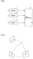
- Fig. 1 is a schematic block diagram showing an apparatus for carrying out an embodiment of the present invention.
- a plurality of cameras 1, 2, ..., N acquire images of a plurality of reference points located on known positions in a three-dimensional space and supply outputs thereof to an image processor 10, which in turn forms images acquired by virtual affine cameras and estimates a three-dimensional position by linear operation.
- Fig. 2 is a conceptual diagram showing a state of acquiring images of a point P in a three-dimensional space with N cameras. Definition of a camera model is now described with reference to Fig. 2. It is assumed that P stands for the point in the three-dimensional space and p stands for the position of its projected image on each image. Expressing these as P_ and p_ on homogeneous coordinates respectively, the following relation is obtained: p_ ⁇ MP_ where M represents a 3 x 4 matrix called a projective matrix, which expresses the projective model, the positions, orientation and optical properties of the cameras.
- Such a camera model is called a perspective camera model if the matrix M can be decomposed as follows: where f u and f v represent the focal lengths of the cameras, u 0 and v 0 represent the image centers, and R and t represent orientation and position of the camera expressed with rotation matrix and translation vector, respectively. These form an ideal model for general cameras.
- P A and p A are expressed in a new coordinate system with the origins at P G and p G respectively.
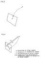
- Fig. 3 is a conceptual diagram of extended cameras
- Fig. 4 is adapted to illustrate correction from projection by perspective cameras to that by affine cameras.
- the relation between the three-dimensional space and a plurality of images acquired by the plurality of cameras is shown. It is assumed that, in case of acquiring images of the point P in the three-dimensional space by the plurality of (N) cameras as described above, p 1 , ..., p N denote projected points of the point P in the respective cameras is shown. These projected points, which are obtained by acquiring images of the point P with the N cameras, can also be regarded as projection of the point P in the three-dimensional space onto 2N-dimensional "image" as shown in Fig. 3.
- the cameras thus projecting the object in the three-dimensional space onto the 2N-dimensional image as shown in Fig. 3 are referred to as extended cameras. It must be noted here that the extended cameras are in a redundant observation system causing no dimensional degeneration from three dimensions.
- p* A C V P A
- C V is in the following relation: p* A represents 2N_ vectors, and C V represents a 2N x 3 matrix.
- the matrix C V corresponds to an affine camera matrix of the extended cameras on the assumption that the respective cameras are affine cameras.
- P A obtained by the expression (5) is a correct three-dimensional position. Namely, this P A is not an approximate solution, but the correct three-dimensional position can be reconstructed under the assumption of the affine cameras. If p* A have noise, on the other hand, the solution of the expression (5) is an estimation minimizing
- Images acquired by perspective cameras are corrected to those equivalent to images acquired by affine cameras here. While epipolar geometric constraint may be employed for this correction, a correction method which is as simple as possible is employed here. The following description is made with reference to extended cameras.
- p* represents images of the point P in the three-dimensional space acquired by the actual N cameras shown in Fig. 1.
- p* A represent images of the point P acquired by these cameras.
- the images p* are corrected to be consistent with p* A . While various methods may be employed for this correction, the k-th element (p* A ) k (1 ⁇ k ⁇ 2N) of p* A is approximated with a second order polynominal of p*, i.e., modeled in the following expression (6): where and T K represents a (2N + 1) x (2N + 1) symmetrical matrix.
- T The degree of freedom of T, which is 2N x (2N + 1) x (N + 1) in total, can conceivably sufficiently describe a perspective camera model. It is to be noted that T is common for all points. T is a parameter decided by the projection method of the actual cameras and the properties and arrangement of the cameras such as the positions and orientations thereof. Therefore, this parameter T can be continuously used unless the cameras are moved or the focal lengths thereof are varied.
- the first stage is a calibration stage for deciding the parameters C V of the virtual extended affine cameras and the parameter T for correction.
- the second stage is an estimation stage for correcting the images acquired by the actual cameras to be equivalent to those projected by the extended affine cameras and linearly estimating the three-dimensional position of the object point.
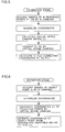
- Figs. 5 and 6 are flow charts of the calibration and estimation stages respectively.
- the image processor shown in Fig. 1 carries out a program based on these flow charts.
- the calibration stage is now described with reference to Fig. 5.
- the extended affine camera matrix C V and the matrix T for correction must be obtained.
- This operation can be regarded as system calibration.
- M reference points P 1 , ..., P M located on previously known three-dimensional positions and projected images p* 1 , ..., p* M obtained by these N cameras. Either a lattice for calibration or an arbitrary sequence of points may be employed.
- the inventive method is an approximate three-dimensional reconstruction method, however, the reference points P 1 , ..., P M are preferably set in an area not much different from that of the three-dimensional space to be estimated in practice.
- the virtual extended affine camera matrix C A is first obtained from the sequence of reference points P 1 , ..., P M .
- the matrix C V may be any matrix, since images acquired by affine cameras can be converted to those acquired by arbitrary affine cameras by affine transformation.
- the matrix T for correction is obtained.
- the extended affine cameras C V acquire images of P j
- p* j is corrected to obtain p* Aj .
- this correction is carried out in accordance with the following expression: Since p* j and p* Aj (1 ⁇ j ⁇ M) are obtained, a linear equation may be solved in relation to the element of the term (2N + 1) x (N + 1) of each T K .
- the virtual affine camera matrix C V and the correction matrix T K (1 ⁇ k ⁇ 2N) 1 are decided from the three-dimensional positions P j of the M reference points and the projected images p* ij thereof by the N cameras.
- the three-dimensional position estimation method is now described with reference to Fig. 6.
- the N cameras acquire images of the object point P to obtain projected images q*, whose coordinates are normalized in consideration of the center of gravity P G of the reference points and the center of gravity p* G in each camera.
- projected images q* A equivalent to those acquired by the virtual extended affine cameras C V correction is made in accordance with the following expression:
- the virtual affine cameras project all reference points once again without knowing correct projective models of the respective cameras for estimating the three-dimensional position, whereby it is possible to estimate the three-dimensional position with no regard to the types, positions and orientations of the cameras. Further, the calculation itself is simple, and the three-dimensional position can be stably estimated in a linear form from the virtual affine cameras. Thus, influence by computational errors or noise can be reduced.
Description
- The present invention relates to a linear estimation method for a three-dimensional position with affine camera correction, and more particularly, it relates to a linear estimation method for a three-dimensional position with affine camera correction for estimating the three-dimensional three-dimensional position of an object point in a space from images acquired by a plurality of cameras in case of controlling a robot or the like with image information.
- A method of acquiring an image of a point (object point) existing in a three-dimensional space with a camera and estimating its three-dimensional position is a central problem of computer vision. Stereoscopy can be referred to as the most basic technique for solving this problem. In the stereoscopy, two cameras located on previously known positions in previously known orientations acquire images of an object point, for deciding its three-dimensional position from the projected images with the principle of triangulation. In such stereoscopy, it is necessary to correctly measure the positions, orientations and focal lengths of the cameras. This is called camera calibration, which has generally been studied in the fields of computer vision and robotics. In this case, the relation by perspective projection is generally employed as the method of describing the relation between the three-dimensional space and the images.
- This perspective projection model can be regarded as an ideal model for general cameras. Despite its correctness, however, this projective model is nonlinear. Due to such non-linearity, three-dimensional position estimation is weak against computation errors or measurement errors of the projected points.
- Study has been made for approximating the perspective projection model with a camera model which has better properties. For example, "Geometric Camera Calibration using Systems of Linear Equations" by Gremban, Thorpe and Kanade, International Conference on Robotics and Automation, pp. 562-567 (1988) applies approximation of a camera model to camera calibration. Thereafter study of an affine camera model has been developed in "Self-Calibration of an Affine Camera from Multiple Views" by Quan, International Journal of Computer Vision, Vol. 19, No. 1, pp. 93-105 (1996). The affine camera model describes a three-dimensional space and images in linear relation. It is known that the affine camera model solves problems resulting from non-linearity and provides sufficiently good approximation of a perspective projection model if the thickness of the object is sufficiently smaller than the distance between the camera and the object.
- "Euclidean Shape and Motion from Multiple Perspective Views by Affine Iterations" by Christy and Horaud, IEEE Transactions on Pattern Analysis and Machine Intelligence, Vol. 18, No. 11, pp. 1098-1104 (1996) describes an applied example of this affine camera model in three-dimensional position estimation. This example is adapted to approximately estimate the three-dimensional position of an object point with an affine camera model for optimizing nonlinear equations obtained from a perspective camera with the approximate value employed as an initial value thereby further correctly estimating the three-dimensional position of the object point. However, this method requires the operation of optimizing the nonlinear equations, and cannot be regarded as a simple solution.
- Multiple-camera stereoscopy employing a plurality of (at least two) cameras forms another flow of the stereoscopy. In the multiple-lens stereoscopy, it is expected that the information content increases as compared with the case of employing only two cameras and the three-dimensional position can be further stably estimated. For example, "Shape and Motion from Image Streams under Orthography: a Factorization Method" by Tomasi and Kanade, International Journal of Computer Vision, Vol. 9, No. 2, pp. 137-154 (1992) describes an example of such multiple-camera stereoscopy. According to Tomasi et al., it is possible to estimate a three-dimensional position by a simple method called a factorization method, if a plurality of orthographic projection cameras can be assumed. If the cameras are not orthographic projection cameras, however, it is necessary to satisfy nonlinear constraint condition called epipolar constraint for three-dimensional position estimation. Therefore, the three-dimensional position cannot be readily estimated.
- Accordingly, a principal object of the present invention is to provide a linear estimation method for a three-dimensional position with affine camera correction, which can reduce influence by computation errors or noise by simplifying estimation of the three-dimensional position of an object point by employing a plurality of images and correcting projected images acquired by cameras modeled by perspective projection to images acquired by a simple linear camera model.
- This object is achieved by a linear estimation method as set forth in claim 1.
- A further development of the invention is given in the dependent claim.
- Briefly stated, the present invention is directed to a method of obtaining the three-dimensional position of an object point with a plurality of cameras, by acquiring images of a plurality of reference points located on known positions in a three-dimensional space with the plurality of cameras, obtaining the coordinates of the projected points on the respective images, assuming a plurality of affine cameras having linear relation between the three-dimensional space and images, calculating how the affine cameras project the respective reference points, and correcting the coordinates of the projected points to be consistent with the projected points.
- According to the present invention, therefore, the virtual affine cameras project all reference points once again without knowing correct projective models of the respective cameras for estimating the three-dimensional position, whereby it is possible to estimate the three-dimensional position with no regard to the types, positions and orientations of the cameras. Further, the calculation itself is simple, the three-dimensional position can be stably estimated in a linear form from the virtual affine cameras, and influence by computation errors or noise can be reduced.
- Coefficients of a second order polynominal of the coordinates of the projected points are regarded as parameters for the correction, for estimating the three-dimensional position of an arbitrary object point in the three-dimensional space in response to decision of the parameters. Further, projected points of the object point are corrected in accordance with the second order polynominal to be consistent with the coordinates of the projected points by the virtual affine cameras, for estimating the three-dimensional position of the object point by linear calculation.
- The foregoing and other objects, features, aspects and advantages of the present invention will become more apparent from the following detailed description of the present invention when taken in conjunction with the accompanying drawings.
-
- Fig. 1 is a schematic block diagram showing an apparatus for carrying out an embodiment of the present invention;
- Fig. 2 is a conceptual diagram showing a state of acquiring images of a point P in a three-dimensional space with N cameras;
- Fig. 3 is a conceptual diagram of extended cameras;
- Fig. 4 is adapted to illustrate correction from projection by perspective cameras to that by affine cameras;
- Fig. 5 is a flow chart of a calibration stage in the embodiment of the present invention; and
- Fig. 6 is a flow chart of an estimation stage.
-
- Fig. 1 is a schematic block diagram showing an apparatus for carrying out an embodiment of the present invention.
- Referring to Fig. 1, a plurality of cameras 1, 2, ..., N acquire images of a plurality of reference points located on known positions in a three-dimensional space and supply outputs thereof to an image processor 10, which in turn forms images acquired by virtual affine cameras and estimates a three-dimensional position by linear operation.
- Fig. 2 is a conceptual diagram showing a state of acquiring images of a point P in a three-dimensional space with N cameras. Definition of a camera model is now described with reference to Fig. 2. It is assumed that P stands for the point in the three-dimensional space and p stands for the position of its projected image on each image. Expressing these as P_ and p_ on homogeneous coordinates respectively, the following relation is obtained:where fu and fv represent the focal lengths of the cameras, u0 and v0 represent the image centers, and R and t represent orientation and position of the camera expressed with rotation matrix and translation vector, respectively. These form an ideal model for general cameras.

- When the first to third columns on the fourth row of a matrix MA are zero, on the other hand, such a camera model is called an affine camera model.

- Returning from the homogeneous coordinate expression to the generally employed Euclidean coordinate expression, the coordinates pA of the projected point p on the images can be related in the affine camera model as follows, assuming that PA represents the three-dimensional coordinates of the point P:
- Fig. 3 is a conceptual diagram of extended cameras, and Fig. 4 is adapted to illustrate correction from projection by perspective cameras to that by affine cameras.
- The relation between the three-dimensional space and a plurality of images acquired by the plurality of cameras is shown. It is assumed that, in case of acquiring images of the point P in the three-dimensional space by the plurality of (N) cameras as described above, p1, ..., pN denote projected points of the point P in the respective cameras is shown. These projected points, which are obtained by acquiring images of the point P with the N cameras, can also be regarded as projection of the point P in the three-dimensional space onto 2N-dimensional "image" as shown in Fig. 3. The cameras thus projecting the object in the three-dimensional space onto the 2N-dimensional image as shown in Fig. 3 are referred to as extended cameras. It must be noted here that the extended cameras are in a redundant observation system causing no dimensional degeneration from three dimensions.
- A coordinate system having the origins at an arbitrary point (generally the center of gravity) and its projected images is employed. It is assumed that PA and pi represent the coordinates of the point P and the projected point on the position P of an image i, to obtain the following expression:

- This can be regarded as the coordinates of the projected points in the extended cameras.
- Assuming that the respective cameras are affine cameras and Ci represents the affine camera matrix in a camera i, the following relation is obtained from the expression (1):
- As to all cameras, the relation can be described as follows:p*A represents 2N_ vectors, and CV represents a 2N x 3 matrix. The matrix CV corresponds to an affine camera matrix of the extended cameras on the assumption that the respective cameras are affine cameras.

- If CV is known under the relation of the expression (3), the three-dimensional position PA of the point P can be solved from the images p*A. The following expression (5) may hold with a pseudo-inverse matrix of CV:
- If the observed values p*A are noiseless, i.e., if p*A are correctly observed, PA obtained by the expression (5) is a correct three-dimensional position. Namely, this PA is not an approximate solution, but the correct three-dimensional position can be reconstructed under the assumption of the affine cameras. If p*A have noise, on the other hand, the solution of the expression (5) is an estimation minimizing ||p*A - CVPA|| , i.e., minimizing errors on images acquired by extended affine cameras. If the extended affine cameras are assumed, the relation between the coordinates PA of the three-dimensional space and the images p*A is linear. It is obvious that resistance against analysis or noise is remarkably superior to that of nonlinear relation, due to the linear relation.
- It has been recognized that the three-dimensional position of the point in the three-dimensional space can be linearly reconstructed if extended affine cameras can be assumed. This is only when affine cameras can be assumed, and it is readily inferable that perspective cameras cannot correctly reconstruct the three-dimensional position in the method of the expression (5) even with noiseless images. If images equivalent to those acquired by affine cameras can be formed from acquired by perspective cameras with some method, however, it must be possible to linearly estimate the three-dimensional position with such images.
- Images acquired by perspective cameras are corrected to those equivalent to images acquired by affine cameras here. While epipolar geometric constraint may be employed for this correction, a correction method which is as simple as possible is employed here. The following description is made with reference to extended cameras.
- As shown in Fig. 4, it is assumed that p* represents images of the point P in the three-dimensional space acquired by the actual N cameras shown in Fig. 1. Considering virtual extended affine cameras provided by the matrix CV, it is assumed that p*A represent images of the point P acquired by these cameras. The images p* are corrected to be consistent with p*A. While various methods may be employed for this correction, the k-th element (p*A)k (1 ≦ k ≦ 2N) of p*A is approximated with a second order polynominal of p*, i.e., modeled in the following expression (6):where
 and TK represents a (2N + 1) x (2N + 1) symmetrical matrix.
- The degree of freedom of T, which is 2N x (2N + 1) x (N + 1) in total, can conceivably sufficiently describe a perspective camera model. It is to be noted that T is common for all points. T is a parameter decided by the projection method of the actual cameras and the properties and arrangement of the cameras such as the positions and orientations thereof. Therefore, this parameter T can be continuously used unless the cameras are moved or the focal lengths thereof are varied.
- A three-dimensional reconstruction method is now described in detail. In order to concretely decide the three-dimensional position of the object point, two stages are necessary. The first stage is a calibration stage for deciding the parameters CV of the virtual extended affine cameras and the parameter T for correction. The second stage is an estimation stage for correcting the images acquired by the actual cameras to be equivalent to those projected by the extended affine cameras and linearly estimating the three-dimensional position of the object point.
- Figs. 5 and 6 are flow charts of the calibration and estimation stages respectively. The image processor shown in Fig. 1 carries out a program based on these flow charts.
- The calibration stage is now described with reference to Fig. 5. In order to reconstruct three-dimensional position information, the extended affine camera matrix CV and the matrix T for correction must be obtained. This operation can be regarded as system calibration. Employed therefor are M reference points P1, ..., PM located on previously known three-dimensional positions and projected images p*1, ..., p*M obtained by these N cameras. Either a lattice for calibration or an arbitrary sequence of points may be employed. Considering that the inventive method is an approximate three-dimensional reconstruction method, however, the reference points P1, ..., PM are preferably set in an area not much different from that of the three-dimensional space to be estimated in practice.
- The virtual extended affine camera matrix CA is first obtained from the sequence of reference points P1, ..., PM. Basically the matrix CV may be any matrix, since images acquired by affine cameras can be converted to those acquired by arbitrary affine cameras by affine transformation. In consideration of the fact that the inventive method is approximation, the parameters of the virtual affine cameras may be selected to be the best approximation of the actual cameras. Assuming that all cameras are affine cameras, there must be the following relation:
- Then, the matrix T for correction is obtained. Assuming that the extended affine cameras CV acquire images of Pj, projection is made on p*Aj = CVPj on the images. p*j is corrected to obtain p*Aj. As hereinabove described, this correction is carried out in accordance with the following expression:Since p*j and p*Aj (1 ≦ j ≦ M) are obtained, a linear equation may be solved in relation to the element of the term (2N + 1) x (N + 1) of each TK.

- On the aforementioned assumption, the virtual affine camera matrix CV and the correction matrix TK (1 ≦ k≦ 2N) 1are decided from the three-dimensional positions Pj of the M reference points and the projected images p*ij thereof by the N cameras.
- The three-dimensional position estimation method is now described with reference to Fig. 6. Similarly to the aforementioned calibration stage, the N cameras acquire images of the object point P to obtain projected images q*, whose coordinates are normalized in consideration of the center of gravity PG of the reference points and the center of gravity p*G in each camera. In order to obtain projected images q*A equivalent to those acquired by the virtual extended affine cameras CV, correction is made in accordance with the following expression:

- With the obtained q*A, the three-dimensional position Q is estimated in accordance with the following expression (8):
- According to the embodiment of the present invention, the virtual affine cameras project all reference points once again without knowing correct projective models of the respective cameras for estimating the three-dimensional position, whereby it is possible to estimate the three-dimensional position with no regard to the types, positions and orientations of the cameras. Further, the calculation itself is simple, and the three-dimensional position can be stably estimated in a linear form from the virtual affine cameras. Thus, influence by computational errors or noise can be reduced.
Claims (2)
- A linear estimation method for obtaining a three-dimensional position of an object point (P) with a plurality of cameras (1, 2, ..., N), including:a first step of acquiring images of a plurality of reference points (P1, ..., Pj, ..., PM) being located on known positions in said three-dimensional space by said plurality of cameras and obtaining coordinates of first projected points (p*1, ..., p*j, ..., p*M) thereof on respective said images;a second step of assuming a plurality of affine cameras having linear relation between said three-dimensional space and images, calculating how said reference points (Pj) are projected by said affine cameras and obtaining corresponding second projected point (p*A1, ..., p*Aj, ..., p*AM) and correcting said coordinates of said first projected points (p*j) to be equivalent with said second projected points (p*Aj) ; and
regarding coefficients of a second order polynominal of said coordinates of said first projected points (p*j) as said parameters for correction; anda third step of estimating the three-dimensional position of an arbitrary object point (P) in said three-dimensional space based on said parameters for correction. - The method of linearly estimating a three-dimensional position in accordance with claim 1, further including a step of correcting third projected points (q*) of said object point (P) with said second order polynominal to be equivalent with the coordinates of fourth projected points (q*A) in said virtual affine cameras and estimating the three-dimensional position of said object point (P) by linear calculation.
Applications Claiming Priority (3)
| Application Number | Priority Date | Filing Date | Title |
|---|---|---|---|
| JP195611/97 | 1997-07-22 | ||
| JP9195611A JP3020898B2 (en) | 1997-07-22 | 1997-07-22 | A linear estimation method of three-dimensional position by affine camera correction |
| JP19561197 | 1997-07-22 |
Publications (2)
| Publication Number | Publication Date |
|---|---|
| EP0902395A1 EP0902395A1 (en) | 1999-03-17 |
| EP0902395B1 true EP0902395B1 (en) | 2000-03-01 |
Family
ID=16344049
Family Applications (1)
| Application Number | Title | Priority Date | Filing Date |
|---|---|---|---|
| EP98111042A Expired - Lifetime EP0902395B1 (en) | 1997-07-22 | 1998-06-16 | Linear estimation method for three-dimensional position with affine camera correction |
Country Status (4)
| Country | Link |
|---|---|
| US (1) | US6137902A (en) |
| EP (1) | EP0902395B1 (en) |
| JP (1) | JP3020898B2 (en) |
| DE (1) | DE69800084T2 (en) |
Families Citing this family (33)
| Publication number | Priority date | Publication date | Assignee | Title |
|---|---|---|---|---|
| US6661913B1 (en) * | 1999-05-05 | 2003-12-09 | Microsoft Corporation | System and method for determining structure and motion using multiples sets of images from different projection models for object modeling |
| JP2000331160A (en) * | 1999-05-24 | 2000-11-30 | Nec Corp | Device and method for matching and recording medium stored with matching program |
| JP3476710B2 (en) * | 1999-06-10 | 2003-12-10 | 株式会社国際電気通信基礎技術研究所 | Euclidean 3D information restoration method and 3D information restoration apparatus |
| KR100584536B1 (en) * | 1999-09-29 | 2006-05-30 | 삼성전자주식회사 | Image processing apparatus for image communication |
| US6313813B1 (en) * | 1999-10-21 | 2001-11-06 | Sony Corporation | Single horizontal scan range CRT monitor |
| FR2801123B1 (en) * | 1999-11-12 | 2002-04-05 | Bertrand Aube | METHOD FOR THE AUTOMATIC CREATION OF A DIGITAL MODEL FROM COUPLES OF STEREOSCOPIC IMAGES |
| US6970591B1 (en) | 1999-11-25 | 2005-11-29 | Canon Kabushiki Kaisha | Image processing apparatus |
| GB2358307B (en) * | 1999-11-25 | 2004-03-24 | Canon Kk | Image processing apparatus |
| US6606406B1 (en) * | 2000-05-04 | 2003-08-12 | Microsoft Corporation | System and method for progressive stereo matching of digital images |
| ITRM20010045A1 (en) | 2001-01-29 | 2002-07-29 | Consiglio Nazionale Ricerche | SYSTEM AND METHOD FOR DETECTING THE RELATIVE POSITION OF AN OBJECT COMPARED TO A REFERENCE POINT. |
| GB2372659A (en) * | 2001-02-23 | 2002-08-28 | Sharp Kk | A method of rectifying a stereoscopic image |
| GB2380887A (en) * | 2001-10-13 | 2003-04-16 | Isis Innovation | Lens distortion correction using correspondence points within images which are constrained to lie on the same epipolar curve |
| FI111755B (en) * | 2001-11-23 | 2003-09-15 | Mapvision Oy Ltd | Method and system for calibrating an artificial vision system |
| JP3983573B2 (en) * | 2002-03-06 | 2007-09-26 | 富士重工業株式会社 | Stereo image characteristic inspection system |
| JP3859574B2 (en) * | 2002-10-23 | 2006-12-20 | ファナック株式会社 | 3D visual sensor |
| US7557966B2 (en) * | 2004-08-11 | 2009-07-07 | Acushnet Company | Apparatus and method for scanning an object |
| JP4737763B2 (en) * | 2006-06-14 | 2011-08-03 | Kddi株式会社 | Free viewpoint image generation method, apparatus and program using multi-viewpoint images |
| JP2008021092A (en) * | 2006-07-12 | 2008-01-31 | Fanuc Ltd | Simulation apparatus of robot system |
| DE102007042963A1 (en) * | 2007-09-10 | 2009-03-12 | Steinbichler Optotechnik Gmbh | Method and device for the three-dimensional digitization of objects |
| US9513765B2 (en) | 2007-12-07 | 2016-12-06 | Sony Corporation | Three-dimensional sliding object arrangement method and system |
| JP5029424B2 (en) * | 2008-02-28 | 2012-09-19 | Jfeスチール株式会社 | Tension stiffness measurement method and apparatus |
| AU2009243439A1 (en) * | 2009-11-30 | 2011-06-16 | Canon Kabushiki Kaisha | Robust image alignment for distributed multi-view imaging systems |
| US9215441B2 (en) * | 2011-02-17 | 2015-12-15 | Konica Minolta, Inc. | Image processing apparatus, non-transitory computer readable recording medium, and image processing method |
| JP2012223839A (en) * | 2011-04-15 | 2012-11-15 | Yaskawa Electric Corp | Robot system, and method for operating robot system |
| US20140348416A1 (en) * | 2013-05-23 | 2014-11-27 | Himax Media Solutions, Inc. | Stereo image rectification apparatus and method |
| US9569850B2 (en) | 2013-10-16 | 2017-02-14 | Cognex Corporation | System and method for automatically determining pose of a shape |
| WO2017131927A1 (en) | 2016-01-26 | 2017-08-03 | Applied Materials, Inc. | Wafer edge ring lifting solution |
| US11075105B2 (en) | 2017-09-21 | 2021-07-27 | Applied Materials, Inc. | In-situ apparatus for semiconductor process module |
| CN108830797A (en) * | 2018-05-24 | 2018-11-16 | 桂林航天工业学院 | A kind of matching line segments method based on affine projection matrix model |
| US10790123B2 (en) | 2018-05-28 | 2020-09-29 | Applied Materials, Inc. | Process kit with adjustable tuning ring for edge uniformity control |
| US11935773B2 (en) * | 2018-06-14 | 2024-03-19 | Applied Materials, Inc. | Calibration jig and calibration method |
| US11289310B2 (en) | 2018-11-21 | 2022-03-29 | Applied Materials, Inc. | Circuits for edge ring control in shaped DC pulsed plasma process device |
| CN113048985B (en) * | 2021-05-31 | 2021-08-06 | 中国人民解放军国防科技大学 | Camera relative motion estimation method under known relative rotation angle condition |
Family Cites Families (4)
| Publication number | Priority date | Publication date | Assignee | Title |
|---|---|---|---|---|
| JP2874710B2 (en) * | 1996-02-26 | 1999-03-24 | 日本電気株式会社 | 3D position measuring device |
| US6009210A (en) * | 1997-03-05 | 1999-12-28 | Digital Equipment Corporation | Hands-free interface to a virtual reality environment using head tracking |
| US6061468A (en) * | 1997-07-28 | 2000-05-09 | Compaq Computer Corporation | Method for reconstructing a three-dimensional object from a closed-loop sequence of images taken by an uncalibrated camera |
| JPH11139506A (en) * | 1997-11-11 | 1999-05-25 | Taisei Denki Kogyo Kk | Refuse compression equipment |
-
1997
- 1997-07-22 JP JP9195611A patent/JP3020898B2/en not_active Expired - Fee Related
-
1998
- 1998-06-16 EP EP98111042A patent/EP0902395B1/en not_active Expired - Lifetime
- 1998-06-16 DE DE69800084T patent/DE69800084T2/en not_active Expired - Fee Related
- 1998-07-15 US US09/115,516 patent/US6137902A/en not_active Expired - Fee Related
Also Published As
| Publication number | Publication date |
|---|---|
| JP3020898B2 (en) | 2000-03-15 |
| US6137902A (en) | 2000-10-24 |
| DE69800084T2 (en) | 2000-09-14 |
| JPH1137721A (en) | 1999-02-12 |
| DE69800084D1 (en) | 2000-04-06 |
| EP0902395A1 (en) | 1999-03-17 |
Similar Documents
| Publication | Publication Date | Title |
|---|---|---|
| EP0902395B1 (en) | Linear estimation method for three-dimensional position with affine camera correction | |
| CN101563709B (en) | Calibrating a camera system | |
| Stein | Lens distortion calibration using point correspondences | |
| Ke et al. | Quasiconvex optimization for robust geometric reconstruction | |
| CN110411476B (en) | Calibration adaptation and evaluation method and system for visual inertial odometer | |
| US7333133B2 (en) | Recursive least squares approach to calculate motion parameters for a moving camera | |
| WO2001004837A2 (en) | Method and apparatus for detecting independent motion in three-dimensional scenes | |
| JP4887376B2 (en) | A method for obtaining a dense parallax field in stereo vision | |
| KR101689335B1 (en) | Method and apparatus for fusing a plurality of data being able to have correlation or uncertainty | |
| Lourakis et al. | Camera self-calibration using the singular value decomposition of the fundamental matrix | |
| JPH0814828A (en) | Calibration method for stereoscopic image sensor and device therefor | |
| McLauchlan | Gauge independence in optimization algorithms for 3D vision | |
| Fusiello | Elements of geometric computer vision | |
| RU2407058C2 (en) | Calculating transformation parametres for image processing | |
| Lee et al. | Large motion estimation for omnidirectional vision | |
| Kanatani et al. | Fundamental matrix from optical flow: optimal computation and reliability evaluation | |
| Kim et al. | Absolute motion and structure from stereo image sequences without stereo correspondence and analysis of degenerate cases | |
| JP2007034964A (en) | Method and device for restoring movement of camera viewpoint and three-dimensional information and estimating lens distortion parameter, and program for restoring movement of camera viewpoint and three-dimensional information and estimating lens distortion parameter | |
| Tang et al. | A factorization-based method for projective reconstruction with minimization of 2-D reprojection errors | |
| Hartley et al. | Reconstruction from six-point sequences | |
| JPH0886609A (en) | Measurement with beam light projection-type three-dimensional sensor, calibration of the sensor and apparatus therefor | |
| Han | Geometric algorithms for least squares estimation of 3-D information from monocular image | |
| Heinrich et al. | Maximum likelihood autocalibration | |
| Nakatsuji et al. | Stabilizing the focal length computation for 3-D reconstruction from two uncalibrated views | |
| Stewénius et al. | Hand-eye calibration using multilinear constraints |
Legal Events
| Date | Code | Title | Description |
|---|---|---|---|
| PUAI | Public reference made under article 153(3) epc to a published international application that has entered the european phase |
Free format text: ORIGINAL CODE: 0009012 |
|
| AK | Designated contracting states |
Kind code of ref document: A1 Designated state(s): DE FR GB |
|
| AX | Request for extension of the european patent |
Free format text: AL;LT;LV;MK;RO;SI |
|
| 17P | Request for examination filed |
Effective date: 19990129 |
|
| 17Q | First examination report despatched |
Effective date: 19990416 |
|
| GRAG | Despatch of communication of intention to grant |
Free format text: ORIGINAL CODE: EPIDOS AGRA |
|
| RIC1 | Information provided on ipc code assigned before grant |
Free format text: 6G 06T 7/00 A |
|
| RTI1 | Title (correction) |
Free format text: LINEAR ESTIMATION METHOD FOR THREE-DIMENSIONAL POSITION WITH AFFINE CAMERA CORRECTION |
|
| RIC1 | Information provided on ipc code assigned before grant |
Free format text: 6G 06T 7/00 A |
|
| RTI1 | Title (correction) |
Free format text: LINEAR ESTIMATION METHOD FOR THREE-DIMENSIONAL POSITION WITH AFFINE CAMERA CORRECTION |
|
| AKX | Designation fees paid |
Free format text: DE FR GB |
|
| GRAG | Despatch of communication of intention to grant |
Free format text: ORIGINAL CODE: EPIDOS AGRA |
|
| GRAH | Despatch of communication of intention to grant a patent |
Free format text: ORIGINAL CODE: EPIDOS IGRA |
|
| GRAH | Despatch of communication of intention to grant a patent |
Free format text: ORIGINAL CODE: EPIDOS IGRA |
|
| GRAA | (expected) grant |
Free format text: ORIGINAL CODE: 0009210 |
|
| AK | Designated contracting states |
Kind code of ref document: B1 Designated state(s): DE FR GB |
|
| REF | Corresponds to: |
Ref document number: 69800084 Country of ref document: DE Date of ref document: 20000406 |
|
| ET | Fr: translation filed | ||
| PLBE | No opposition filed within time limit |
Free format text: ORIGINAL CODE: 0009261 |
|
| STAA | Information on the status of an ep patent application or granted ep patent |
Free format text: STATUS: NO OPPOSITION FILED WITHIN TIME LIMIT |
|
| 26N | No opposition filed | ||
| REG | Reference to a national code |
Ref country code: GB Ref legal event code: IF02 |
|
| PGFP | Annual fee paid to national office [announced via postgrant information from national office to epo] |
Ref country code: GB Payment date: 20020610 Year of fee payment: 5 |
|
| PGFP | Annual fee paid to national office [announced via postgrant information from national office to epo] |
Ref country code: FR Payment date: 20020617 Year of fee payment: 5 |
|
| PGFP | Annual fee paid to national office [announced via postgrant information from national office to epo] |
Ref country code: DE Payment date: 20020701 Year of fee payment: 5 |
|
| PG25 | Lapsed in a contracting state [announced via postgrant information from national office to epo] |
Ref country code: GB Free format text: LAPSE BECAUSE OF NON-PAYMENT OF DUE FEES Effective date: 20030616 |
|
| PG25 | Lapsed in a contracting state [announced via postgrant information from national office to epo] |
Ref country code: DE Free format text: LAPSE BECAUSE OF NON-PAYMENT OF DUE FEES Effective date: 20040101 |
|
| GBPC | Gb: european patent ceased through non-payment of renewal fee |
Effective date: 20030616 |
|
| PG25 | Lapsed in a contracting state [announced via postgrant information from national office to epo] |
Ref country code: FR Free format text: LAPSE BECAUSE OF NON-PAYMENT OF DUE FEES Effective date: 20040227 |
|
| REG | Reference to a national code |
Ref country code: FR Ref legal event code: ST |