EP0902391A2 - Printing control apparatus and method - Google Patents
Printing control apparatus and method Download PDFInfo
- Publication number
- EP0902391A2 EP0902391A2 EP98307274A EP98307274A EP0902391A2 EP 0902391 A2 EP0902391 A2 EP 0902391A2 EP 98307274 A EP98307274 A EP 98307274A EP 98307274 A EP98307274 A EP 98307274A EP 0902391 A2 EP0902391 A2 EP 0902391A2
- Authority
- EP
- European Patent Office
- Prior art keywords
- paper
- printing
- stapling
- positions
- binding
- Prior art date
- Legal status (The legal status is an assumption and is not a legal conclusion. Google has not performed a legal analysis and makes no representation as to the accuracy of the status listed.)
- Granted
Links
Images


Classifications
-
- G—PHYSICS
- G06—COMPUTING OR CALCULATING; COUNTING
- G06F—ELECTRIC DIGITAL DATA PROCESSING
- G06F3/00—Input arrangements for transferring data to be processed into a form capable of being handled by the computer; Output arrangements for transferring data from processing unit to output unit, e.g. interface arrangements
- G06F3/12—Digital output to print unit, e.g. line printer, chain printer
- G06F3/1297—Printer code translation, conversion, emulation, compression; Configuration of printer parameters
-
- G—PHYSICS
- G06—COMPUTING OR CALCULATING; COUNTING
- G06F—ELECTRIC DIGITAL DATA PROCESSING
- G06F40/00—Handling natural language data
- G06F40/10—Text processing
- G06F40/103—Formatting, i.e. changing of presentation of documents
- G06F40/106—Display of layout of documents; Previewing
Definitions
- This invention relates to a printing control apparatus and method for controlling a device such as a printing device having a binding function for binding together a plurality of sheets of output paper output by the device.
- a system in which printing is performed using a computer conventionally includes a function according to which the printer in such a system outputs a specified number of copies of the printed document.
- a copier has a stapling function for binding together the printout on a per-copy basis in order to eliminate the labor involved in gathering the printout together copy by copy when a plurality of copies have been made, as well as the labor involved in binding the copies together.
- a concern of the present invention is to provide a printing control apparatus and method whereby a printing device having a binding function can be controlled and excellent operability assured.
- a printing control apparatus for controlling a printing device having a function for binding paper output by the printing device, comprising size setting means for setting paper size, display means for deciding, in dependence upon the set paper size, positions at which binding can be performed, and displaying these positions as candidates, selecting means for selecting a desired position from the candidates displayed, and transmitting means for transmitting the position selected by the selecting means to the printing device as a binding position.
- the present invention provides a printing control method for controlling a printing device having a function for stapling paper output by the printing device, comprising a size setting step of setting paper size, a display step of deciding, in dependence upon the set paper size, positions at which binding can be performed, and displaying these positions as candidates, a selecting step of selecting a desired position from the candidates displayed, and a transmitting step of transmitting the position selected at the selecting step to the printing device.
- the present invention provides a computer readable storage medium storing a computer program in accordance with which printing is performed by a printing device having a function for binding paper output by the printing device, comprising size setting processing code for setting paper size, display processing code for deciding, in dependence upon the set paper size, positions at which binding can be performed, and displaying these positions as candidates, selecting processing code for selecting a desired position from the candidates displayed, and transmitting processing code for transmitting the position selected by the selecting processing to the printing device.
- the computer program can be obtained in electronic form for example by downloading the code over a network such as the internet.
- an electrical signal carrying processor implementable instructions for controlling a processor to carry out the method as hereinbefore described.
- a printing system will be described as an embodiment of the present invention.
- the system includes a printer, which has a stapling stacker for binding printouts together on a per-copy basis and retaining the printouts in a stack, and a host computer that uses the printer.
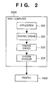
- Fig. 1 is a block diagram of a printing system comprising a host computer 3000 and a printer 1500.
- the host computer 3000 has a CPU 1 which, on the basis of a document processing program that has been stored in the program ROM of a ROM 3, executes the document processing of a document containing a mixture of graphics, images, characters and tables (inclusive of spreadsheets, etc.).
- the CPU 1 performs overall control of various devices connected to a system bus 4.
- a RAM 2 functions as the main memory and work area of the CPU 1.
- a keyboard controller (KBC) 5 controls inputs from a keyboard 9 and pointing device, which is not shown.
- a CRT controller (CRTC) 6 controls the display on a CRT display 10. A screen for setting a printer, described later, also is displayed on the CRT 10.
- a disk controller (DKC) 7 controls access to an external memory 11, such as a hard disk (HD) or floppy disk (FD), which stores a booting program, various applications, font data, user files and edited files, etc.
- a printer controller (PRTC) 8 which is connected to a printer 1500 via a bidirectional interface 21, executes processing for controlling communication with the printer 1500.
- the CPU 1 executes processing to rasterize outline fonts in a display information RAM, provided in, say, the RAM 2, and makes possible implementation of a WYSIWYG (What You See I What You Get) function using the CRT 10.
- the CPU 1 besides executing a program for implementing the flowchart of a procedure, described later, opens various windows that have been registered and executes a variety of data processing on the basis of commands designated by a mouse cursor (not shown) on the CRT 10.
- the printer 1500 has a CPU 12 which, on the basis of a control program stored in a program ROM of a ROM 13, outputs an image signal, which serves as output information, to a printing unit (printer engine) 17 connected printing unit interface (I/F) 16.
- the printing unit 17 includes a stapling stacker 171 in addition to a mechanism for performing printer. Though the stapling stacker 171 is separate from the printer, it is shown as being part of the printing unit 17 because it operates in cooperation with the printing unit.
- a RAM 19 functions as the main memory and work area of the CPU 12.
- An input unit 18 controls communication of status information such as printing status information with the host computer 3000 via the bidirectional interface 21 and is capable of notifying the host computer 3000 of information internal to the printer.
- a memory controller (MC) 20 controls access to an external memory 14 such as a hard disk (HD) or floppy disk (FD) which stores a booting program, various applications, font data, user files and edited files, etc.
- a control panel 1501 which includes a display panel and keyboard, supplies information to the operator and inputs commands from the operator.
- Fig. 17 is a sectional view of the printer 1500 and shows the principal components of a mechanism of the printing unit 17.
- a laser driver 221 drives a laser emission unit 211, whereby the latter is caused to emit a laser beam that conforms to image data received from the host computer 3000.
- the laser beam illuminates a photosensitive drum 212 so that a latent image conforming to the laser beam is formed on the drum.
- a developing agent is applied to the latent image on the photosensitive drum 212 by a developing device 213.
- a sheet of recording paper is supplied from a cassette 214 or cassette 205 and transported to transfer unit 206 at a timing synchronized to the start of illumination by the laser beam, whereby the developing agent affixed to the photosensitive drum 212 is transferred to the recording paper.
- the sheet of recording paper carrying the developing agent is transported to a fixing unit 207, which proceeds to fix the developing agent to the recording paper by the application of heat and pressure.
- the sheet of recording paper that has passed through the fixing unit 207 is discharged by discharge rollers 208, and the stapling stacker 171 staples a prescribed number of discharged sheets of recording paper together and places the stapled sheets in respective bins to assort the recording paper. If stapling processing is executed, recording paper that has been introduced to the stapling stacker 171 is placed on a stapling table 215 without being discharged from the printer. When a prescribed number of sheets have accumulated, the sheets of recording paper are stapled together by a stapling unit 216.
- the stapling position therefore, is limited to the trailing edge of the paper with regard to the transport direction and, because of the mechanism involved, is limited to both ends of this edge and to a location between these ends.
- the recording paper is received by the uppermost bin. If double-sided printing has been set, the recording paper is transported to the discharge rollers 208, after which the discharge rollers 208 are rotated in the reverse direction so that the recording paper is introduced to the paper transport path again by a flapper 209. If multiple printing has been set, the recording paper is introduced to the paper transport path again by a flapper 209 so as not to be transported to the discharge rollers 208. Recording paper that has been introduced to the paper transport path again is supplied to the transfer unit 206 at the above-mentioned timing.
- print data generated by an application 201 is delivered to a graphics engine 202, which is part of the operating system, in response to a print request from the application.
- the graphics engine 202 utilizes a printer driver 203 specific to the printer 1500 to generate print data suited to the printer 1500.
- the printer driver 203 delivers the generated data to a system spooler 204. The latter spools the print data and sends the print data to the printer in accordance with the printer schedule.
- the printer driver at this time transmits information for controlling the stapling stacker to the printer 1500 together with the print data based upon a stapling setting through a procedure that will be described later.
- Fig. 3 shows an example of a memory map of the RAM 2 when printing is performed by the host computer 1500 or when the printer is set.
- An application 32 performs printing using an operating system (OS) 36 and a printing program (printer driver) 35.
- a basic input/output interface (BIOS) 37 includes a program for driving a parallel interface or serial interface, etc., connected to the printer 1500.
- Related data 34 includes setting information relating to settings for printing, such as paper size and layout information, as well as setting information relating to a stapling function, described later, used upon being set by the printer driver.
- the user configures printing processing in dependence upon the printer used.
- One example is to configure printing processing in such a manner that when the user calls printer setting provided by the operating system or the like, a printer driver is called from the operating system, a screen for deciding setting information specific to the printer is displayed and setting is performed on the display screen. Setting is performed in accordance with this method in the present embodiment.
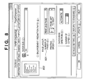
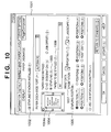
- Fig. 10 is an example of a screen for printer set-up when printer set-up has been called by the user.
- information, details, paper, layout and paper discharge, etc. are decided for each setting, and the user selects the screen in dependence upon the information to be set.
- Fig. 10 shows an example in which a "PAPER DISCHARGE" screen 1001 has been selected from the above.
- the user utilizes a pointing device such as a mouse or a keyboard to set such items as the paper discharge port and stapling position on this display screen, thereby setting stapling.
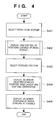
- Fig. 4 is a flowchart of a procedure for setting stapling on the display screen of Fig. 10.
- the operation for setting stapling is premised on installation of the stapling stacker 171. If a "STAPLING STACKER INSTALLED" box 1002 and a “STAPLING” box 1003 have not been checked, therefore, no display is presented in a bitmap display window 1004 and stapling cannot be set. More specifically, the procedure of Fig. 4 is executed when the printing setting screen is called and the "PAPER DISCHARGE" setting is selected from the screen on the assumption that the "STAPLING STACKER INSTALLED" box 1002 and a "STAPLING” box 1003 have been checked. Alternatively, the procedure is executed when the "PAPER DISCHARGE” setting is selected and the "STAPLING" box 1003 is checked.
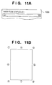
- paper size is set in a "PAPER TO BE STAPLED" text box 1006 at step S401.
- Fig. 11A shows the text box 1006 in the highlighted state. This indicates that a setting has been made in the text box 1006.
- the size of the paper to be stapled is specified as being size A4 in Figs. 10 and 11A
- the specified size is stored in the RAM 2 as related data.
- Positions at which stapling can and cannot be performed are displayed in a "STAPLING POSITION" area 1005 in Fig. 10 at step S402.
- the stapling unit 216 can perform stapling at any of three locations at one edge of the paper, namely at both ends of one edge and at a position between both ends. Accordingly, candidates for positions at which stapling is possible are corners (1), (3), (6) and (8) of the paper and locations (2), (4), (5) and (7) on respective edges between the corners, for a total of eight positions, as shown in Fig. 11B.
- the orientation of paper placed on a paper tray is decided by the size of the paper and the paper is transported in this orientation to print on the paper or discharge the paper.
- the edge on which stapling can be carried out therefore, is limited to one edge that conforms to the orientation of the paper placed on the tray.
- stapling is limited to the trailing edge in regard to the direction in which the paper is transported.
- stapling of the edge opposite the edge that can be stapled is capable of being supported by rotating the image recorded on the paper 180° in order to turn the image upside down. Accordingly, positions at which stapling can and cannot be performed are generated from among the eight positions (1) - (8) in Fig. 11B in dependence upon the orientation of the paper decided by the paper size.
- step S402 the positions at which stapling can be performed are displayed in the "STAPLING POSITION" area 1005, which specifies the stapling positions, thereby making selection of these positions possible. Positions at which stapling cannot be performed are not displayed (i.e., the positions are dimmed), thereby making selection of these position impossible.
- position 1 positions 3 through 6 and position 8 (these are underlined candidates) are capable of being selected; the other positions are not.
- the encircled numerals (1) - (8) correspond to the positions 1 through 8 specified in Figs. 4 and 10.
- Fig. 5 illustrates the details of step S402.
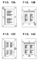
- step S501 in Fig. 5 all stapling positions in the "STAPLING POSITION" area 1005 are enabled temporarily, and the set paper size is discriminated at step S502, with the flow of processing branching depending upon the paper size. If the size that has been set is legal size, positions 2, 4, 5, and 7 are dimmed at step S503 to disable these positions so that they cannot be selected.
- Fig. 12A shows an example the display in such case. If the size that has been set is leisure size or sizes A3, B4, positions 4, 5 are dimmed at step S504 to disable them.
- Fig. 12C shows an example of the display in this case.
- positions 2, 7 are dimmed at step S505 to disable them.
- Fig. 12B shows an example of the display in this case. Thus, positions capable of being specified based upon paper size are selected and displayed.
- step S403 the user is allowed to specify the desired stapling position from among the stapling positions being displayed in the "STAPLING POSITION" area 1005.
- the display performed at step S402 and the selection made at step S403 are implemented utilizing functions provided by the operating system. Any dimmed ratio button that has been checked by the user is ignored and is not dealt with as being selected. It should be noted that processing is executed in the initial state in such a manner that an appropriate position is selected in this state.
- bitmap image in the form of the recording paper is displayed in the bitmap display window 1004 at step S404.
- the bitmap image represents the selected stapling position, a separately specified page layout and stapling orientation, as well as an orientation specified by a "PRINT DATA ORIENTATION" area 1007 shown in Fig. 10.
- the image displayed in the window 1004 reflects the number of pages to be printed on one sheet of paper, this having been set in a "PAGE LAYOUT: NUMBER OF PAGES” area 801 on a paper setting screen shown in Fig. 8, as well as the stapling orientation set in a "STAPLING ORIENTATION” area depicted in Fig. 10.
- the window 1004 shown in Fig. 10 is displayed as the printing of one page based upon the setting made in Fig. 8. If "PRINT TWO PAGES" has been specified, then an image indicative of the printing of two pages shown in Fig. 13B is displayed in the window 1004 of Fig. 10.
- the long left edge or long top edge has been specified at the stapling edge.
- the reason for this is that the long edge on the right side of the paper is stapled in case of a portrait orientation whereas the long edge on the top side of the paper is stapled in case of landscape orientation. Accordingly, a display indicating that the long edge on the left side of the paper is the stapling edge is presented on the page image in window 1004 of Fig. 10 as well. Though the edge stapled is indicated by hatching in Fig. 10, this edge can be indicated by a light-gray display if desired.
- the selected stapling position is displayed within the paper image in the display window 1004 in the form of a mark 1004a indicative of the selected stapling position.
- Fig. 6 is a flowchart illustrating the details of step S404.
- a bitmap in line with this setting is selected from bitmap images prepared in advance and the selected bitmap image is displayed at step S601 in Fig. 6.
- the orientation of the print data is the portrait orientation
- the image of a vertically oriented sheet of paper is selected.
- the orientation of the print data is the landscape orientation
- the image of a horizontally oriented sheet of paper is selected.
- an image indicating the manner in which two pages are formed on one sheet of paper is selected.
- the position of the mark 1004a is decided from the stapling position specified in the "STAPLING POSITION" area 1005 and is displayed at step S602. This is followed by step S603, at which the specified edge is decided in accordance with the selected stapling orientation, and this edge is displayed in a distinguishable manner.
- a mark that reflects the orientation of the staple is selected in conformity with the stapling position.
- step S405 in Fig. 4 symbols representing positions at which stapling is possible and a symbol representing the specified stapling position are displayed in the display window 1004.
- the symbols are the encircled numerals.
- Fig. 7 is a flowchart illustrating the details of step S405.
- positions at which stapling can be performed decided by the specified paper size are acquired at step S701. These positions are the same as those displayed as being designatable in the "STAPLING POSITION" area 1005.
- the numbers of the positions at which stapling can be performed are displayed sequentially from 1 to 8. That is, it is determined at step S704 whether stapling is possible. If stapling is not possible, the position is not displayed. If stapling is possible, then it is determined at step S705 whether this position has been designated as a stapling position.
- step S707 the symbol (encircled numeral) indicating this position is displayed at step S707 in bright blue at the portion corresponding to the specified position in the bitmap display window 1004. If the position has been not been designated as a stapling position, on the other hand, then the symbol indicating this position is displayed at step S706 in dark blue at the portion corresponding to this position in the bitmap display window 1004. In Fig. 10, the difference between these two colors is indicated by the thicknesses of the lines of the characters. The thick line indicates a position that has been designated. By performing this operation in regard to the eight locations shown in Fig. 11B, the encircled numerals will be displayed in the manner shown in the bitmap display window 1004 of Fig. 10.
- designatable stapling positions are displayed in conformity with the designation of paper size.
- an image representing the format of a page that reflects the setting of five items can be displayed in the bitmap display window 1004 in dependence upon the five items, namely the designation of paper size, the designation of page layout, the designation of stapling orientation, the designation of print data orientation and the designation of stapling position.
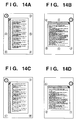
- Figs. 13A - 13D and Figs. 14A - 14H are examples of images displayed in the bitmap display window 1004 of Fig. 10.
- Figs. 14A - 14H are examples of images displayed in a case where the layout setting is for the printing of one page on one sheet of paper, with the stapling orientation being set at the left or top.
- the stapling position is set at (1) in all of the diagrams of Figs. 14A - 14H.
- the designations of paper size and print data orientation are as follows:
- Figs. 14G and 14H illustrates cases where (3) has been designated at the stapling position for legal-size paper.
- the user Since the content of a display is thus changed in dependence upon the orientation of print data so as to reflect the orientation, the user is capable of setting a stapling position intuitively just as if he or she were actually reading the document while holding it.
- Figs. 13A, 13B are examples of displays in a case where a page layout has been set so as to print two pages on one sheet of paper. Paper size is set at A4 and the stapling orientation is set as left or top.
- each page of ordinary size is reduced to about 70% of ordinary size and the two reduced pages are placed side by side or one above the other.
- the orientation of the paper becomes that obtained by rotating the set print data orientation by 90°.
- Figs. 13D, 13D are examples of displays in a case where a page layout has been set so as to print four pages on one sheet of paper.
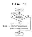
- Fig. 15 is a flowchart of a procedure for monitoring a state in which stapling is not possible, namely a state in which a designated stapling position is not suited to the paper size.
- step S1501 it is determined at step S1501 whether a stapling position designatable at a designated paper size has been set as a stapling position. If stapling is not possible, a warning message is output by display or voice at step S1502.
- a stapling position that can be designated at a designated paper size canbe selected, and therefore stapling is always possible.
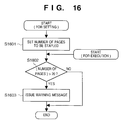
- Fig. 16 is a flowchart of processing for monitoring instances where a number of pages designated so that they may be bound by stapling exceeds the number of pages that can be bound.
- monitoring is performed in the following manner:
- step S1601 it is determined at step S1602 whether the set number of pages has exceeded 20. If the answer is "YES", then a visual or voice message is output to warn the user at step S1603.
- the setting of the number of pages at step S1601 is not limited to a manual operation performed by the user. There are cases where the number of pages that should be printed is provided by the application program.
- step S1602 onward a procedure similar to that from step S1602 onward is performed whenever one page of data is generated at execution of printing. If more than 20 pages have been designated as the number of copies to be bound, a warning message is output in similar fashion.
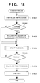
- Figs. 18 and 19 illustrate procedures executed by the printer driver when a printing job is created using a stapling setting established in accordance with Fig. 4 and the job is output to the printer 1500.
- the print job is of the type in which print data is preceded by job preprocessing and succeeded by job post-processing.
- the print data has a format in accordance with which one page of print data is preceded by page preprocessing and succeeded by page post-processing on a page by page basis.
- Job preprocessing is created at step S1801 in Fig. 18. If stapling has been designated ("YES" at step S1802), then stapling designation is added onto the job preprocessing at step S1803. This designation includes a designation of stapling position. It should be noted that the procedure of Fig. 15 for discriminating whether stapling is possible or not may be executed as a part of step S1801. If it is determined that stapling is not possible, then, after a warning is issued, the setting may be performed again or the stapling designation may be ignored.
- step S1804 at which page data is created for every page. This step is repeated until the creation of page data for all pages is completed ("YES" at step S1805). This is followed by the creation of job post-processing at step S1806. Created data equivalent to one print job is sent to the printer at step S1807.
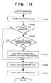
- Fig. 19 is a flowchart of a procedure for creating page data at step S1804.
- Page preprocessing is crated at step S1901.
- the page preprocessing includes page layout designation, etc.
- step S1902 at which it is determined whether stapling has been designated. If the answer is "YES”, then it is determined at step S1903 whether the stapling position is on the side of the stapling unit. If paper size is A4, for example, at the time of printing, the paper is transported upon arranging it so that the left side of the paper will be at the front if the orientation of the print data is the portrait orientation and so that the upper side of the paper will be at the front if the orientation of the print data is the landscape orientation.
- the stapling position will be the trailing edge in terms of the transport direction, i.e., the right side of the paper if the print data has the portrait orientation and the lower side of the paper if the print data has the landscape orientation. Accordingly, taking Fig. 14A as an example, stapling can be performed only at positions (3), (5) and (8). If positions (1), (4) and (6) have been designated, therefore, printing is performed upon rotating the image by 180° and the designated location is bound by stapling.
- a page rotation command for rotating the image by 180° is added onto the page preprocessing at step S1904 if the designated stapling position is not on the side of the stapling unit. This is followed by step S1905, at which one page of print data is created, and then by step S1906, at which page post-processing is created. The processing of Fig. 19 is then terminated.
- the printer that has thus been sent the print data rotates the image to be generated, performs stapling at the stapling position specified by job pre-processing and outputs the printed matter.
- the user is allowed to specify the stapling position from among positions, decided based upon the paper, at which stapling is possible. As a result, it is possible to prevent a situation in which a position at which stapling is impossible is designated, an error that is usually noticed after the start of printing.
- positions capable of being set as stapling positions also are displayed on the bitmap image, it is easy to ascertain the stapling position.
- a document can be bound at a desired position by stapling even if a stapling unit has been provided for only one edge.
- a processing procedure through which a screen of the kind shown in Fig. 10 is displayed regardless of the stapling designation.
- the operator is capable of setting a stapling position while observing the image displayed in the display window 1004.
- the procedures of Figs. 20A, 20B are used instead of the procedure shown in Fig. 4 of the first embodiment.
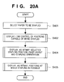
- Fig. 20A is a flowchart of a procedure for displaying an image in the display window 1004 on the display screen of Fig. 10.
- paper size is set in the "PAPER TO BE STAPLED" text box 1006 at step S401.
- Fig. 11A shows the text box 1006 in the highlighted state. This indicates that a setting has been made in the text box 1006.
- the size of the paper to be stapled is specified as being size A4 in Figs. 10 and 11A.
- the specified size is stored in the RAM 2 as related data.
- bitmap image in the form of the recording paper is displayed in the bitmap display window 1004 at step S404.
- the bitmap image represents the selected stapling position, a separately specified page layout and stapling orientation, as well as an orientation specified by the "PRINT DATA ORIENTATION" area 1007 shown in Fig. 10. Initially, no stapling position will have been designated. All stapling positions capable of being designated, therefore, are displayed in an unselected state.
- stapling positions capable of being designated in dependence upon the designation of paper size are displayed and, if a stapling position has been designated, so is the designated stapling position.
- an image representing the format of a page that reflects the setting of five items can be displayed in the display window 1004 in dependence upon the five items, namely the designation of paper size, the designation of page layout, the designation of stapling orientation, the designation of print data orientation and the designation of stapling position.
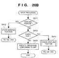
- Fig. 20B is a processing procedure for a case where an input has been made on the screen of Fig. 10. It is determined at step S411 in Fig. 20B whether the entered item is stapling position. The user is allowed to designated the desired stapling position from the stapling position displayed in the "STAPLING POSITION" area 1005 of Fig. 10. The user designates stapling position, etc., while observing the screen displayed through the procedure of Fig. 20A. This selection is made utilizing functions provided by the operating system. Any dimmed portion that has been checked by the user is ignored and is not dealt with as being selected.
- step S412 processing branches to step S401 in Fig. 20A and the screen of Fig. 10 is updated. It is determined at step S413 whether the input is designation of paper size. If the answer is "YES”, the procedure of Fig. 15 is executed at step S414, where it is determined whether the designated stapling position and the designated paper size conform. An alarm is issued if the two do not conform. Processing then branches to step S401 in Fig. 20 to update the screen of Fig. 10.
- Fig. 21 is a cross-sectional view of a printer having a punching unit 218 and a punching bin 217. Paper discharged from the discharge rollers 208 is transported to the punching unit 218 or the stapling unit 216 in accordance with a path determined by a flapper 219.
- a user instructs to use the punching function and designates a punching position or positions and a pitch of holes from a computer, connected to the printer, similarly to when utilizing the stapling function described in the first embodiment.
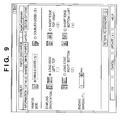
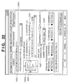
- Fig. 22 shows an example of an image displayed on a display screen of the computer for setting a position or positions to be punched.
- the image corresponds to Fig. 10 of the first and second embodiments; therefore, differing points between Figs. 22 and 10 are explained.
- punching is designated by checking a "PUNCHING" box 2001. Accordingly, a "NUMBER/PITCH” text box 2007 is displayed, and the user sets the number and pitch of a hole or holes in the text box 2007. Note, no hole can be punched at a corner of the paper, differing from stapling. Therefore, the numbers 1 ⁇ to 4 ⁇ , representing sides that can be punched, are displayed as candidates in the window 1004.
- 1 ⁇ and 2 ⁇ represent the long sides
- 3 ⁇ and 4 ⁇ represent the short sides.
- the positions 5 to 8 in a "STAPLING/PUNCHING POSITION" area 2005 can not be designated, and when one of these positions is selected, the selection is ignored.
- the user designates the side to be punched in the area 2005 while checking the window 1004, further designates the number and pitch of holes to be made in the text box 2007.
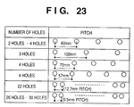
- Fig. 23 is a table of available number/pitch of holes. For making two holes, for instance, a pitch of 80 mm may be selected; for punching four holes, one of pitches 80 mm, 70 mm, and 57 mm may be selected. It is possible to add pitches other than above, of course.
- the punching unit capable of changing pitch and number of holes may be realized with one punching cutter by repeating punching operation the designated number of times after moving by a designated pitch. Note, when the number of holes to be made is limited to two or four, for instance, a mechanism for punching simultaneously may be realized by providing the same number of punching cutters as the limit number of holes.
- the setting of hole positions is performed by almost the same procedure as for stapling explained in the first embodiment if "stapling" is substituted by "punching". More specifically, except that paper is punched in the third embodiment while paper is stapled in the first embodiment, the setting of hole positions is performed in almost the same procedure described with reference to Figs. 4 to 7, Figs. 15 and 16, and Figs. 18 to 20. However, there are slight differences in the procedure between stapling and punching, the differences are explained below.
- the printer of the third embodiment conveys paper of legal size, leisure size, A3 and B4 in the lengthwise direction, whereas paper of letter size, A4, for example in the widthwise direction. Therefore, the areas where punching can be performed in paper of, e.g., leisure size are the sides 3 ⁇ and 4 ⁇ , and, in paper of, e.g., the other size, the sides 1 ⁇ and 2 ⁇ . Accordingly, in steps S503 and S504 in Fig. 5, the positions 1 and 2 are excluded, and in steps S505, the positions 3 and 4 are excluded.
- the present invention can be applied to a system constituted by a plurality of devices (e.g., a host computer, interface, reader, printer, etc.) or to an apparatus comprising a single device (e.g., a copier or facsimile machine, etc.).
- a host computer e.g., a host computer, interface, reader, printer, etc.
- an apparatus e.g., a copier or facsimile machine, etc.
- the object of the present invention can also be achieved by providing a system or apparatus with a storage medium storing the program codes of the procedures shown in Figs. 4 through 7, Figs. 15 and 16 and Figs. 18 through 20B for performing the aforesaid functions of the foregoing embodiments, reading the program codes with a computer (or CPU or MPU) of the system or apparatus from the storage medium, and then executing the program codes.
- the program codes read from the storage medium implement the novel functions of the invention, and the storage medium storing the program codes constitutes the invention.
- the storage medium for storing the program codes can be a floppy disk, hard disk, optical disk, magneto-optical disk, CD-ROM, CD-R, magnetic tape, nonvolatile type memory card or ROM, by way of example.
- the present invention covers a case where an operating system or the like working on the computer performs a part of or the entire process in accordance with the designation of program codes and implements the functions according to the embodiments.
- the present invention further covers a case where, after the program codes read from the storage medium are written in a function extension board inserted into the computer or in a memory provided in a function extension unit connected to the computer, a CPU or the like contained in the function extension board or function extension unit performs a part of or the entire process in accordance with the designation of program codes and implements the functions of the above embodiments.
- the user is allowed to specify a stapling position from among positions, decided based upon the paper, at which stapling is possible. As a result, it is possible to prevent a situation in which a position at which stapling is impossible is designated. Thus, an error that is usually noticed only after the start of printing can be avoided.
- a document can be bound at a desired position by stapling even if the printing device is one capable of performing stapling at only one edge.
Landscapes
- Engineering & Computer Science (AREA)
- Theoretical Computer Science (AREA)
- Physics & Mathematics (AREA)
- General Engineering & Computer Science (AREA)
- General Physics & Mathematics (AREA)
- Health & Medical Sciences (AREA)
- Human Computer Interaction (AREA)
- Artificial Intelligence (AREA)
- Audiology, Speech & Language Pathology (AREA)
- Computational Linguistics (AREA)
- General Health & Medical Sciences (AREA)
- Folding Of Thin Sheet-Like Materials, Special Discharging Devices, And Others (AREA)
- Paper Feeding For Electrophotography (AREA)
- Accessory Devices And Overall Control Thereof (AREA)
- Control Or Security For Electrophotography (AREA)
Abstract
Description
portrait (stapling position: (3))
landscape (stapling position: (3))
data orientation: landscape; stapling
position: (1)
data orientation: portrait; stapling
position: (3)
data orientation: portrait; stapling position: (5)
data orientation: landscape; stapling
position: (5)
Claims (20)
- A printing control apparatus for controlling a printing device having a function for binding paper output by the printing device, characterized by having:size setting means (S401) for setting paper size;display means (S402) for deciding, in dependence upon the set paper size, positions at which binding can be performed, and displaying these positions as candidates;selecting means (S403) for selecting a desired position from the candidates displayed; andtransmitting means (S1807) for transmitting the position selected by said selecting means to said printing device as a binding position.
- A printing control apparatus according to claim 1, characterized by further having display means for displaying an image indicating a shape of the paper that conforms to orientation of print data, and displaying, in distinguishable fashion on said image, the positions, decided by said selecting means, at which binding can be performed, as well as the selected position.
- A printing control apparatus according to claim 2, characterized in that said display means (S404) displays a designated stapling orientation on the image indicating the shape of the paper.
- A printing control apparatus according to claim 2 or 3, characterized in that said display means (S404) displays a designated page layout on the image indicating the shape of the paper.
- A printing control apparatus according to claim 1, characterized by further having incompatibility detecting means (S1501) for detecting incompatibility between set paper size and a position selected by said selecting means, and issuing a warning when incompatibility is detected.
- A printing control apparatus according to claim 1, characterized by further having second incompatibility detecting means (S1601, S1602) for detecting that number of pages to be bound is a number of pages incapable of being stapled, and issuing a warning when this is detected.
- A printing control apparatus according to claim 1, characterized in that said transmission means (S1807) further transmits an instruction, which inverts an image to be printed, to said printing device in a case where a position that has been selected by said selecting means is located at an edge opposite an edge at which printing is performed by said printing device.
- A printing control method for controlling a printing device having a function for binding paper output by the printing device, characterized by having:a size setting step of setting paper size;a display step of deciding, in dependence upon the set paper size, positions at which binding can be performed, and displaying these positions as candidates;a selecting step of selecting a desired position from the candidates displayed; and atransmitting step of transmitting the position selected at said selecting step to said printing device.
- A printing control method according to claim 8, characterized in that said display step displays an image indicating a shape of the paper that conforms to orientation of print data, and displays, in distinguishable fashion on said image, the positions, decided by said selecting means, at which binding can be performed, as well as the selected position.
- A printing control method according to claim 8 or 9, characterized in that said display step further displays a designated binding orientation on the image indicating the shape of the paper.
- A printing control method according to claims 8 through 10, characterized in that said display step further displays a designated page layout on the image indicating the shape of the paper.
- A printing control method according to claim 8, characterized by further having an incompatibility detecting step of detecting incompatibility between set paper size and a position selected at said selecting step, and issuing a warning when incompatibility is detected.
- A printing control method according to claim 8, characterized by further having a second incompatibility detecting step of detecting that number of pages to be bound is a number of pages incapable of being stapled, and issuing a warning when this is detected.
- A printing control method according to claim 8, characterized in that said transmission step further transmits an instruction, which inverts an image to be printed, to said printing device in a case where a position that has been selected at said selecting step is located at an edge opposite an edge at which printing is performed by said printing device.
- A printing control apparatus according to claim 1, wherein the function for binding the paper is a stapling function.
- A printing control apparatus according to claim 1, wherein the function for binding the paper is a punching function for punching a hole to bind the paper.
- A control apparatus for controlling a printing device having a function for binding papers output by the printing device, comprising:input means for inputting a plurality of instructions relating to printing, including a paper binding instruction;discriminating means for, when the paper binding instruction is inputted, discriminating positions, at which said printing device can bind papers and which way vary depending on other input instruction(s) relating to printing; anddisplay control means for controlling a display device so as to graphically display the positions discriminated by said discriminating means.
- A control method for controlling a printing device having a function for binding papers output by the printing device, comprising steps of:inputting a plurality of instructions relating to printing, including a paper binding instruction;when the paper binding instruction is inputted, discriminating positions at which said printing device can bind papers and which way vary depending on other input instruction(s) relating to printing; andcontrolling a display device so as to graphically display the positions discriminated in said discriminating step.
- A storage medium storing processor implementable instructions for controlling a printing device to carry out the method of any one of claims 8 to 14 and claim 18.
- An encoded signal carrying digital instructions for controlling a printing device to carry out the method of any one of claims 8 to 14 and claim 18.
Priority Applications (1)
| Application Number | Priority Date | Filing Date | Title |
|---|---|---|---|
| EP07007756A EP1811430B1 (en) | 1997-09-11 | 1998-09-09 | Printer |
Applications Claiming Priority (3)
| Application Number | Priority Date | Filing Date | Title |
|---|---|---|---|
| JP24721397 | 1997-09-11 | ||
| JP24721397 | 1997-09-11 | ||
| JP247213/97 | 1997-09-11 |
Related Child Applications (1)
| Application Number | Title | Priority Date | Filing Date |
|---|---|---|---|
| EP07007756A Division EP1811430B1 (en) | 1997-09-11 | 1998-09-09 | Printer |
Publications (3)
| Publication Number | Publication Date |
|---|---|
| EP0902391A2 true EP0902391A2 (en) | 1999-03-17 |
| EP0902391A3 EP0902391A3 (en) | 2000-03-22 |
| EP0902391B1 EP0902391B1 (en) | 2007-04-18 |
Family
ID=17160137
Family Applications (2)
| Application Number | Title | Priority Date | Filing Date |
|---|---|---|---|
| EP07007756A Expired - Lifetime EP1811430B1 (en) | 1997-09-11 | 1998-09-09 | Printer |
| EP98307274A Expired - Lifetime EP0902391B1 (en) | 1997-09-11 | 1998-09-09 | Printing control apparatus and method |
Family Applications Before (1)
| Application Number | Title | Priority Date | Filing Date |
|---|---|---|---|
| EP07007756A Expired - Lifetime EP1811430B1 (en) | 1997-09-11 | 1998-09-09 | Printer |
Country Status (3)
| Country | Link |
|---|---|
| US (1) | US6406199B1 (en) |
| EP (2) | EP1811430B1 (en) |
| DE (1) | DE69837583T2 (en) |
Cited By (5)
| Publication number | Priority date | Publication date | Assignee | Title |
|---|---|---|---|---|
| EP1150200A3 (en) * | 2000-04-27 | 2006-03-29 | Canon Kabushiki Kaisha | Print control apparatus, and storage medium |
| US7586639B2 (en) | 2004-07-30 | 2009-09-08 | Canon Kabuhsiki Kaisha | Information processing apparatus, print processing method, and computer program |
| EP1764227A3 (en) * | 2005-09-14 | 2011-10-05 | Kyocera Mita Corporation | Image forming apparatus using sheet post-processing information |
| RU2461057C2 (en) * | 2009-09-09 | 2012-09-10 | Кэнон Кабусики Кайся | Image forming apparatus, control method for said apparatus and machine-readable data medium |
| EP3934221A1 (en) | 2015-05-08 | 2022-01-05 | Canon Kabushiki Kaisha | Printing apparatus, method for controlling printing apparatus, and storage medium |
Families Citing this family (19)
| Publication number | Priority date | Publication date | Assignee | Title |
|---|---|---|---|---|
| JP2000175022A (en) * | 1998-12-08 | 2000-06-23 | Canon Inc | Information recording device |
| JP3984762B2 (en) | 1999-07-23 | 2007-10-03 | キヤノン株式会社 | Host computer, control method therefor, and computer-readable recording medium |
| JP2001209471A (en) * | 2000-01-27 | 2001-08-03 | Fuji Photo Film Co Ltd | Operation screen simplified creation system for remote control terminal |
| US20030081102A1 (en) * | 2001-09-05 | 2003-05-01 | Tomas Roztocil | Method of determining a number of sequentially ordered pages in an ordered media set |
| US7359084B2 (en) * | 2002-02-06 | 2008-04-15 | Canon Kabushiki Kaisha | Preview display for multiple-sided printing |
| US6712446B1 (en) | 2002-12-12 | 2004-03-30 | Hewlett-Packard Development Company, L.P. | Controlling printing in response to print media characteristics |
| US20050007613A1 (en) * | 2003-07-09 | 2005-01-13 | Fritz Terry M. | Imaging system control panel method and apparatus |
| JP4155915B2 (en) * | 2003-12-03 | 2008-09-24 | ニスカ株式会社 | Sheet post-processing apparatus and image forming apparatus |
| JP3814626B2 (en) * | 2004-04-05 | 2006-08-30 | キヤノン株式会社 | Image forming system, control method, storage medium, program, and image forming apparatus |
| JP4401850B2 (en) * | 2004-04-16 | 2010-01-20 | キヤノン株式会社 | Document processing apparatus and method |
| US20060082816A1 (en) * | 2004-10-15 | 2006-04-20 | Lexmark International, Inc. | Printer device and related method for handling print-and-hold jobs |
| US20060133842A1 (en) * | 2004-12-16 | 2006-06-22 | Kabushiki Kaisha Toshiba | Printing apparatus |
| JP4880414B2 (en) * | 2006-09-29 | 2012-02-22 | 京セラミタ株式会社 | Input display device, electronic device, and input display program |
| JP4594406B2 (en) * | 2008-03-07 | 2010-12-08 | シャープ株式会社 | Post-processing equipment |
| JP5147822B2 (en) * | 2009-12-26 | 2013-02-20 | キヤノン株式会社 | Image forming apparatus, image forming apparatus control method and program |
| JP6122349B2 (en) * | 2013-06-13 | 2017-04-26 | キヤノン株式会社 | Image forming apparatus, printing control method, and program |
| CN105335337B (en) * | 2014-06-17 | 2017-12-19 | 北大方正集团有限公司 | The method for splitting and device of cross-page file |
| US9798505B1 (en) * | 2016-09-28 | 2017-10-24 | Konica Minolta Laboratory U.S.A., Inc. | System and method of printing using mixed paper sizes |
| JP7095363B2 (en) * | 2018-03-30 | 2022-07-05 | ブラザー工業株式会社 | installer |
Family Cites Families (26)
| Publication number | Priority date | Publication date | Assignee | Title |
|---|---|---|---|---|
| JPS5974558A (en) | 1982-10-21 | 1984-04-27 | Dainippon Screen Mfg Co Ltd | Layout recording method of copy picture |
| JPS62159163A (en) * | 1986-01-06 | 1987-07-15 | Minolta Camera Co Ltd | Copying machine |
| US4878656A (en) * | 1987-03-20 | 1989-11-07 | Canon Kabushiki Kaisha | Sheet finisher |
| US5053831A (en) * | 1988-02-18 | 1991-10-01 | Minolta Camera Kabushiki Kaisha | Image forming apparatus having a finisher |
| JPH0643156B2 (en) * | 1988-03-14 | 1994-06-08 | キヤノン株式会社 | Sheet post-processing device |
| US5490243A (en) * | 1990-12-13 | 1996-02-06 | F3 Software Corporation | Data processing system for multi-platform print control and electronic data fill |
| US5113222A (en) * | 1991-01-22 | 1992-05-12 | Eastman Kodak Company | Reproduction apparatus with improved display for use in job set-up |
| JP2856561B2 (en) * | 1991-03-29 | 1999-02-10 | シャープ株式会社 | Image forming device with post-processing device |
| JP3359662B2 (en) * | 1992-08-19 | 2002-12-24 | 株式会社リコー | Image forming system device |
| US5422743A (en) * | 1992-12-23 | 1995-06-06 | Xerox Corporation | Operator invoked document defect repair templates |
| DE4491655T1 (en) * | 1993-03-17 | 1995-04-27 | Ricoh Kk | Image recording device |
| JP3630705B2 (en) * | 1993-08-02 | 2005-03-23 | コニカミノルタビジネステクノロジーズ株式会社 | Digital copying machine |
| JPH0795335A (en) * | 1993-09-24 | 1995-04-07 | Toshiba Corp | Image forming memory |
| US5678135A (en) * | 1994-06-21 | 1997-10-14 | Ricoh Company, Ltd. | Image forming apparatus for a multiplex copying system |
| US5722031A (en) * | 1994-08-25 | 1998-02-24 | Canon Kabushiki Kaisha | Image forming apparatus having stapler for stapling sheets |
| JPH08278728A (en) * | 1995-04-10 | 1996-10-22 | Ricoh Co Ltd | Image forming device |
| US5749040A (en) * | 1995-07-20 | 1998-05-05 | Canon Kabushiki Kaisha | Image forming apparatus capable of correcting curl of sheet |
| JPH0937028A (en) * | 1995-07-20 | 1997-02-07 | Canon Inc | Image processing device |
| US5771103A (en) * | 1995-08-31 | 1998-06-23 | Kabushiki Kaisha Toshiba | Image forming apparatus performing interruption process in electronic sorting mode |
| JP3172067B2 (en) * | 1995-08-31 | 2001-06-04 | 株式会社東芝 | Image forming apparatus and image forming method |
| US6111659A (en) * | 1995-09-26 | 2000-08-29 | Matsushita Electric Industrial Co., Ltd. | Digital copier with image scanner apparatus and offline image data and control data interface |
| US6314213B1 (en) * | 1996-09-19 | 2001-11-06 | Canon Kabushiki Kaisha | Image processing apparatus and method which process image on the basis of direction of document |
| US6173088B1 (en) * | 1996-10-01 | 2001-01-09 | Canon Kabushiki Kaisha | Image forming method and apparatus |
| JP3533871B2 (en) * | 1997-03-05 | 2004-05-31 | ミノルタ株式会社 | Image forming device |
| JP4073515B2 (en) * | 1997-03-06 | 2008-04-09 | コニカミノルタビジネステクノロジーズ株式会社 | Image forming apparatus |
| US6205452B1 (en) * | 1997-10-29 | 2001-03-20 | R. R. Donnelley & Sons Company | Method of reproducing variable graphics in a variable imaging system |
-
1998
- 1998-09-09 DE DE69837583T patent/DE69837583T2/en not_active Expired - Lifetime
- 1998-09-09 EP EP07007756A patent/EP1811430B1/en not_active Expired - Lifetime
- 1998-09-09 EP EP98307274A patent/EP0902391B1/en not_active Expired - Lifetime
- 1998-09-10 US US09/151,350 patent/US6406199B1/en not_active Expired - Lifetime
Cited By (5)
| Publication number | Priority date | Publication date | Assignee | Title |
|---|---|---|---|---|
| EP1150200A3 (en) * | 2000-04-27 | 2006-03-29 | Canon Kabushiki Kaisha | Print control apparatus, and storage medium |
| US7586639B2 (en) | 2004-07-30 | 2009-09-08 | Canon Kabuhsiki Kaisha | Information processing apparatus, print processing method, and computer program |
| EP1764227A3 (en) * | 2005-09-14 | 2011-10-05 | Kyocera Mita Corporation | Image forming apparatus using sheet post-processing information |
| RU2461057C2 (en) * | 2009-09-09 | 2012-09-10 | Кэнон Кабусики Кайся | Image forming apparatus, control method for said apparatus and machine-readable data medium |
| EP3934221A1 (en) | 2015-05-08 | 2022-01-05 | Canon Kabushiki Kaisha | Printing apparatus, method for controlling printing apparatus, and storage medium |
Also Published As
| Publication number | Publication date |
|---|---|
| EP1811430A2 (en) | 2007-07-25 |
| EP0902391B1 (en) | 2007-04-18 |
| EP1811430B1 (en) | 2012-02-01 |
| EP0902391A3 (en) | 2000-03-22 |
| DE69837583T2 (en) | 2007-12-27 |
| EP1811430A3 (en) | 2009-08-19 |
| US6406199B1 (en) | 2002-06-18 |
| DE69837583D1 (en) | 2007-05-31 |
Similar Documents
| Publication | Publication Date | Title |
|---|---|---|
| EP1811430B1 (en) | Printer | |
| US7827493B2 (en) | Data processing apparatus, data processing method of data processing apparatus, and computer-readable memory medium storing program therein | |
| US6229984B1 (en) | Image forming apparatus which prevents improper stapling and punching operations | |
| US8520251B2 (en) | Information processing apparatus, information processing method, and computer program | |
| JP5100350B2 (en) | Print control apparatus, print control method, and print control program | |
| US20010044868A1 (en) | System and method for visual representation and manipulation of tabs on a production printer | |
| JP3805122B2 (en) | Information processing apparatus, print setting method thereof, and storage medium storing computer-readable printer driver program | |
| JP7826001B2 (en) | Information processing device, program, and method for controlling information processing device | |
| US8553241B2 (en) | Information processing apparatus, information processing method, and storage medium for generating print data according to an instruction | |
| US6827514B1 (en) | Printer with bookbinding function for binding printed matter | |
| CN102253814A (en) | Information processing apparatus and control method thereof | |
| JP2005115683A (en) | Print setting method and information processing apparatus | |
| JP3782588B2 (en) | Information processing apparatus, host computer, and processing method in information processing apparatus | |
| US7108435B2 (en) | Printing control apparatus and method, and printing system | |
| JP2001038978A (en) | Print control device and print control method | |
| JP3833211B2 (en) | Printing control apparatus and processing method | |
| JP2006127537A (en) | Printing control apparatus and method | |
| EP1195266A2 (en) | System and method for visual representation and manipulation of tabs on a product printer | |
| JP4498268B2 (en) | Information processing apparatus, print processing method, and storage medium | |
| US8400669B2 (en) | Information processing apparatus and staple attribute setting method | |
| JP5832163B2 (en) | Information processing apparatus, print setting method, and program | |
| US8160469B2 (en) | Information processing apparatus, method for controlling the information processing apparatus, and storage medium | |
| JP2006330898A (en) | Print setting apparatus, print setting condition method, program for realizing functions of print setting apparatus, and recording medium | |
| JPH1191217A (en) | Printing processor | |
| JP4176098B2 (en) | Image forming apparatus and image forming system |
Legal Events
| Date | Code | Title | Description |
|---|---|---|---|
| PUAI | Public reference made under article 153(3) epc to a published international application that has entered the european phase |
Free format text: ORIGINAL CODE: 0009012 |
|
| AK | Designated contracting states |
Kind code of ref document: A2 Designated state(s): DE FR GB |
|
| AX | Request for extension of the european patent |
Free format text: AL;LT;LV;MK;RO;SI |
|
| PUAL | Search report despatched |
Free format text: ORIGINAL CODE: 0009013 |
|
| AK | Designated contracting states |
Kind code of ref document: A3 Designated state(s): AT BE CH CY DE DK ES FI FR GB GR IE IT LI LU MC NL PT SE |
|
| AX | Request for extension of the european patent |
Free format text: AL;LT;LV;MK;RO;SI |
|
| RIC1 | Information provided on ipc code assigned before grant |
Free format text: 7G 06K 15/00 A, 7G 06F 3/12 B, 7G 03G 15/00 B |
|
| 17P | Request for examination filed |
Effective date: 20000802 |
|
| AKX | Designation fees paid |
Free format text: DE FR GB |
|
| 17Q | First examination report despatched |
Effective date: 20040209 |
|
| GRAP | Despatch of communication of intention to grant a patent |
Free format text: ORIGINAL CODE: EPIDOSNIGR1 |
|
| GRAS | Grant fee paid |
Free format text: ORIGINAL CODE: EPIDOSNIGR3 |
|
| GRAA | (expected) grant |
Free format text: ORIGINAL CODE: 0009210 |
|
| AK | Designated contracting states |
Kind code of ref document: B1 Designated state(s): DE FR GB |
|
| REF | Corresponds to: |
Ref document number: 69837583 Country of ref document: DE Date of ref document: 20070531 Kind code of ref document: P |
|
| ET | Fr: translation filed | ||
| PLBE | No opposition filed within time limit |
Free format text: ORIGINAL CODE: 0009261 |
|
| STAA | Information on the status of an ep patent application or granted ep patent |
Free format text: STATUS: NO OPPOSITION FILED WITHIN TIME LIMIT |
|
| 26N | No opposition filed |
Effective date: 20080121 |
|
| REG | Reference to a national code |
Ref country code: FR Ref legal event code: PLFP Year of fee payment: 18 |
|
| PGFP | Annual fee paid to national office [announced via postgrant information from national office to epo] |
Ref country code: FR Payment date: 20150928 Year of fee payment: 18 |
|
| PGFP | Annual fee paid to national office [announced via postgrant information from national office to epo] |
Ref country code: GB Payment date: 20160914 Year of fee payment: 19 |
|
| REG | Reference to a national code |
Ref country code: FR Ref legal event code: ST Effective date: 20170531 |
|
| PG25 | Lapsed in a contracting state [announced via postgrant information from national office to epo] |
Ref country code: FR Free format text: LAPSE BECAUSE OF NON-PAYMENT OF DUE FEES Effective date: 20160930 |
|
| PGFP | Annual fee paid to national office [announced via postgrant information from national office to epo] |
Ref country code: DE Payment date: 20171130 Year of fee payment: 20 |
|
| GBPC | Gb: european patent ceased through non-payment of renewal fee |
Effective date: 20170909 |
|
| PG25 | Lapsed in a contracting state [announced via postgrant information from national office to epo] |
Ref country code: GB Free format text: LAPSE BECAUSE OF NON-PAYMENT OF DUE FEES Effective date: 20170909 |
|
| REG | Reference to a national code |
Ref country code: DE Ref legal event code: R071 Ref document number: 69837583 Country of ref document: DE |