EP0902292B1 - Method for correcting the signal of a speed sensor - Google Patents
Method for correcting the signal of a speed sensor Download PDFInfo
- Publication number
- EP0902292B1 EP0902292B1 EP98112646A EP98112646A EP0902292B1 EP 0902292 B1 EP0902292 B1 EP 0902292B1 EP 98112646 A EP98112646 A EP 98112646A EP 98112646 A EP98112646 A EP 98112646A EP 0902292 B1 EP0902292 B1 EP 0902292B1
- Authority
- EP
- European Patent Office
- Prior art keywords
- wheel
- speed
- signal
- counter reading
- correction
- Prior art date
- Legal status (The legal status is an assumption and is not a legal conclusion. Google has not performed a legal analysis and makes no representation as to the accuracy of the status listed.)
- Expired - Lifetime
Links
- 238000000034 method Methods 0.000 title claims description 32
- 238000012937 correction Methods 0.000 claims description 41
- 238000001914 filtration Methods 0.000 claims description 2
- 230000008859 change Effects 0.000 description 7
- 238000001514 detection method Methods 0.000 description 5
- 238000004458 analytical method Methods 0.000 description 4
- 238000011156 evaluation Methods 0.000 description 4
- 238000004364 calculation method Methods 0.000 description 3
- 230000005284 excitation Effects 0.000 description 3
- 238000004519 manufacturing process Methods 0.000 description 3
- 238000012935 Averaging Methods 0.000 description 2
- 230000001133 acceleration Effects 0.000 description 2
- 230000008901 benefit Effects 0.000 description 2
- 230000001419 dependent effect Effects 0.000 description 2
- 230000006870 function Effects 0.000 description 2
- 230000008569 process Effects 0.000 description 2
- 230000000630 rising effect Effects 0.000 description 2
- 238000005070 sampling Methods 0.000 description 2
- 238000001228 spectrum Methods 0.000 description 2
- 230000009897 systematic effect Effects 0.000 description 2
- 230000009466 transformation Effects 0.000 description 2
- 229930091051 Arenine Natural products 0.000 description 1
- 239000010426 asphalt Substances 0.000 description 1
- 238000009530 blood pressure measurement Methods 0.000 description 1
- 238000005314 correlation function Methods 0.000 description 1
- 238000005260 corrosion Methods 0.000 description 1
- 230000007797 corrosion Effects 0.000 description 1
- 238000013461 design Methods 0.000 description 1
- 238000011161 development Methods 0.000 description 1
- 230000008030 elimination Effects 0.000 description 1
- 238000003379 elimination reaction Methods 0.000 description 1
- 238000005516 engineering process Methods 0.000 description 1
- 230000006872 improvement Effects 0.000 description 1
- 230000001939 inductive effect Effects 0.000 description 1
- 239000000463 material Substances 0.000 description 1
- 238000012544 monitoring process Methods 0.000 description 1
- 238000012545 processing Methods 0.000 description 1
- 239000004575 stone Substances 0.000 description 1
- 238000000844 transformation Methods 0.000 description 1
Images

Classifications
-
- G—PHYSICS
- G01—MEASURING; TESTING
- G01P—MEASURING LINEAR OR ANGULAR SPEED, ACCELERATION, DECELERATION, OR SHOCK; INDICATING PRESENCE, ABSENCE, OR DIRECTION, OF MOVEMENT
- G01P3/00—Measuring linear or angular speed; Measuring differences of linear or angular speeds
- G01P3/42—Devices characterised by the use of electric or magnetic means
- G01P3/44—Devices characterised by the use of electric or magnetic means for measuring angular speed
- G01P3/48—Devices characterised by the use of electric or magnetic means for measuring angular speed by measuring frequency of generated current or voltage
- G01P3/481—Devices characterised by the use of electric or magnetic means for measuring angular speed by measuring frequency of generated current or voltage of pulse signals
- G01P3/489—Digital circuits therefor
-
- B—PERFORMING OPERATIONS; TRANSPORTING
- B60—VEHICLES IN GENERAL
- B60C—VEHICLE TYRES; TYRE INFLATION; TYRE CHANGING; CONNECTING VALVES TO INFLATABLE ELASTIC BODIES IN GENERAL; DEVICES OR ARRANGEMENTS RELATED TO TYRES
- B60C23/00—Devices for measuring, signalling, controlling, or distributing tyre pressure or temperature, specially adapted for mounting on vehicles; Arrangement of tyre inflating devices on vehicles, e.g. of pumps or of tanks; Tyre cooling arrangements
- B60C23/06—Signalling devices actuated by deformation of the tyre, e.g. tyre mounted deformation sensors or indirect determination of tyre deformation based on wheel speed, wheel-centre to ground distance or inclination of wheel axle
- B60C23/061—Signalling devices actuated by deformation of the tyre, e.g. tyre mounted deformation sensors or indirect determination of tyre deformation based on wheel speed, wheel-centre to ground distance or inclination of wheel axle by monitoring wheel speed
- B60C23/062—Frequency spectrum analysis of wheel speed signals, e.g. using Fourier transformation
-
- B—PERFORMING OPERATIONS; TRANSPORTING
- B60—VEHICLES IN GENERAL
- B60T—VEHICLE BRAKE CONTROL SYSTEMS OR PARTS THEREOF; BRAKE CONTROL SYSTEMS OR PARTS THEREOF, IN GENERAL; ARRANGEMENT OF BRAKING ELEMENTS ON VEHICLES IN GENERAL; PORTABLE DEVICES FOR PREVENTING UNWANTED MOVEMENT OF VEHICLES; VEHICLE MODIFICATIONS TO FACILITATE COOLING OF BRAKES
- B60T8/00—Arrangements for adjusting wheel-braking force to meet varying vehicular or ground-surface conditions, e.g. limiting or varying distribution of braking force
- B60T8/17—Using electrical or electronic regulation means to control braking
- B60T8/173—Eliminating or reducing the effect of unwanted signals, e.g. due to vibrations or electrical noise
-
- G—PHYSICS
- G01—MEASURING; TESTING
- G01P—MEASURING LINEAR OR ANGULAR SPEED, ACCELERATION, DECELERATION, OR SHOCK; INDICATING PRESENCE, ABSENCE, OR DIRECTION, OF MOVEMENT
- G01P3/00—Measuring linear or angular speed; Measuring differences of linear or angular speeds
- G01P3/42—Devices characterised by the use of electric or magnetic means
- G01P3/44—Devices characterised by the use of electric or magnetic means for measuring angular speed
- G01P3/48—Devices characterised by the use of electric or magnetic means for measuring angular speed by measuring frequency of generated current or voltage
- G01P3/481—Devices characterised by the use of electric or magnetic means for measuring angular speed by measuring frequency of generated current or voltage of pulse signals
Definitions
- the invention relates to a method for determining speed-independent Frequencies of a useful signal component from a rectangular one Signal, the frequency of which is proportional to the speed, by means of an electronic control unit for motor vehicles according to the preamble of claim 1.
- the method according to the invention is preferred for estimating the tire air pressure by determining the resonance frequencies in the wheel-tire system of a vehicle used.
- the invention is based on the example of this application explained in more detail.
- the rectangular signal whose frequency is proportional speed is preferably done with an encoder wheel produced in the form of an ABS pulse wheel with 48 teeth. In the ff the rectangular signal whose frequency is proportional to the speed is called a rectangular speed signal for short.
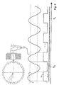
- the method for detecting the speed signal is shown in FIG. 2.
- An inductive speed sensor scans and generates the teeth of the encoder wheel from a certain speed a sinusoidal signal S1. This is in the control unit or already in the sensor itself in a rectangular Speed signal S2 converted.
- a counter (signal S3) runs along with the duration of the pulse Allocates meter reading or tooth value. From such a process started to explain the invention in the following.
- the possibility of evaluating the resonance frequencies is heavily dependent from the excitation of the tire vibrations.
- the performance of the Useful signals e.g. resonance frequencies to be evaluated
- the interference signal e.g. frequencies due to errors in the encoder wheel or due to tire irregularities.
- the useful signal corresponds to the (Wheel) speed change due to uneven road surfaces (the ones to be evaluated Wheel-tire resonance vibrations are from the road excited), while the interference signal of the (wheel) speed change due to component tolerances. Tolerances lead to constant Driving speed at different distances between the pulse edges and thus pretend wrong (wheel) speeds.
- the resonance frequencies in the signal can be determined. If the excitation from the street is of the same order of magnitude Interference signal is (highway, asphalt), falsify errors in speed detection the evaluation. In addition, frequency analysis for example the pressure frequency of the wheel and not the Wheel-tire resonance vibration detected.
- the method according to the invention uses systematic recurrence the error (pitch error of the encoder wheel teeth, unbalance due to wheel irregularities) to eliminate them. For each tooth of the impulse wheel the error is learned that it has compared to a target value (mean value). The factors determined in this way serve to correct the measured values Values.
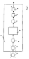
- FIG. 1 shows an electronic control unit 1, preferably a control unit for braking systems (e.g. ABS / ASC) in motor vehicles, which receives as input signal the speed signal S1 (FIG. 2) of a speed sensor 2, which has a specific number (z. B. 48) of equidistant teeth encoder wheel (z. B. ABS pulse wheel, Fig. 2) cooperates.
- a rectangular speed signal S2 is generated in the rectangular pulse converter 3 from the sinusoidal signal S1, the frequency of which is proportional to the speed (called sinusoidal speed signal S1 for short).
- the rectangular pulse shaper 3 can also be contained in the sensor 2.
- the rectangular pulse shaper 3 is connected to a counter unit 4 (see also signal S3, FIG.
- the correction method of the method according to the invention is carried out in the correction unit 5.
- the output signal of the correction unit 5 is a speed signal which has been corrected by learning correction factors from errors which occur periodically over one revolution.
- This adjusted speed signal also contains the speed-independent frequencies of the useful signal component, in the present example the resonance frequencies of the wheel system. In order to evaluate these resonance frequencies, the cleaned speed signal is passed on to the frequency evaluation unit 7 via the bandpass filter 6.
- the frequency analysis unit 7 is by evaluating the zero crossings of x 0, filtered v i of the filtered velocity signal determines the actual resonance frequency of the wanted signal as well as the deviation of this actual resonant frequency of a predetermined desired resonant frequency.
- a change in the tire air pressure p is estimated as a function of the determined deviation and is transmitted, for example, to a display or warning unit, not shown here.
- FIG. 3 shows the correction method for all 48 by the correction method according to the invention Correction values or correction factors obtained for teeth of the encoder wheel shown.
- a division error is caused by the correction value assigned to tooth 15 F, which due to an uneven tooth width (see also signal S2 in Fig. 2) has been eliminated.
- the correction factors of all teeth extending over one revolution for example sinusoidal unbalance vibration, the frequency of which depends on the speed is eliminated.
- FIGS. 4 and 5 show the correction method for determining that shown in FIG. 3 Correction method explained in more detail.
- the average speed is recorded.
- the average speed i.e. the mean of the meter reading
- one Pulse before and after a pulse are calculated, whereby at least one division error is detected.
- Counter readings of a quarter turn used before and after whereby half a wheel revolution is detected. This allows both Pitch errors as well as wheel irregularity errors can be eliminated.
- advantage here is that the deviations from the average speed Faults regardless of sections of the encoder wheel or ABS pulse wheel Getting corrected. Deviations occurring periodically with one wheel revolution are therefore have no influence on the speed values to be calculated.
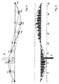
- Fig. 4 are nine sample points P9, the counter readings as examples or correspond to the tooth values of nine of the 48 teeth per revolution, represented at one revolution. A tooth-related correction after a deviation is marked with arrows.
- an index i is assigned to each tooth of the pulse wheel.
- the assignment is established after a sensor threshold has been exceeded at a certain speed (eg v> 1 km / h). It is important that the learned correction values are available within a few seconds if possible, so that the detection of a pressure drop can be quickly ensured.
- the current and the last 24 recorded counter readings corresponding to half a wheel revolution are used. It is assumed that the correction values of all teeth are recalculated every revolution and the assumption is made that the longitudinal acceleration of the vehicle changes only slightly in the short time interval under consideration.
- the correction factor k i-12 becomes the previously measured counter reading ⁇ i-12 (e.g. also P3; P4; P5; P6; P7, Fig. 4) calculated, which represents the counter reading a quarter of a revolution before.
- the calculation of the correction factors k i follows from the linear representation of the speed curve (FIG. 5) between the tooth value t i-24 corrected with the correction factor detected in this wheel revolution (e.g. also P1; P2; P3; P4; P5, Fig 4) and the tooth value t i , equation 2, corrected with the correction factor calculated from the previous revolution, a linear course is formed between the reference points i and i-24 .
- the detected counter reading i-12 is just placed on the linear line to this sampling point.
- the correction factor ⁇ i-12 required for this is calculated from equation 2.
- ⁇ i-12 ⁇ i ⁇ (1 + k i ) ⁇ .DELTA.t b + ⁇ i-24 ⁇ (1 + k i-24 ) ⁇ .DELTA.t a ⁇ i-12 ⁇ (At b + ⁇ t a ) - 1
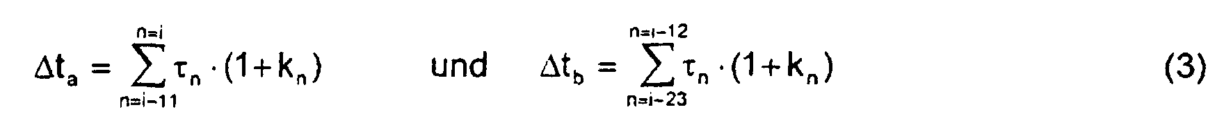
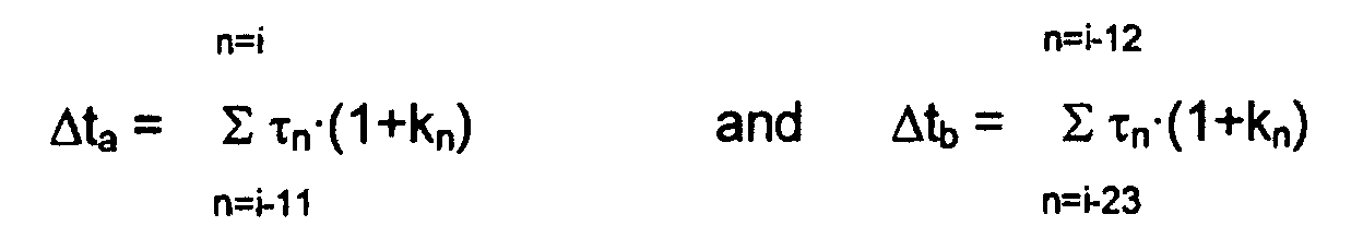
- the two time periods ⁇ t a and ⁇ t b are each calculated using equation 3.
- the correction factors are filtered, for example, in order to reduce the influence of the vehicle acceleration (ie no linear course of the straight line in FIG. 5) and the road profile.
- This filter calculates a weighted average between the correction factors of the current and previous revolution, equation 4.
- the factor a is adjusted during the running time of the method. In the beginning, a small value a ensures that the correct k value settles quickly; after a while the factor a is increased, which means that the useful signal is less filtered and the resolution and accuracy of the resonance frequency calculation is increased.
- the correction factors are continuously updated because they are speed-dependent.
- Fig. 3 shows the determined Correction factors after, for example, ten wheel revolutions. Clear the course of the deviations corresponding to one revolution is visible (F and vibration over one revolution).
- the initialization phase e.g. at the end of the line or after reassembly and balancing the wheel
- Serious changes to this picture or falling below a specified threshold of the correlation function between the currently recorded and saved state can be used to avoid an imbalance or other irregularity Lock the wheel.
- a warning algorithm can cause impermissible deviations detect this image from a target image and issue a warning, if the deviations fall below a certain correlation threshold.
- the corrected and averaged speed values preferably with a Bandpass filtered.
- the center frequency of the bandpass corresponds approximately to that resonant frequency of interest.
- a very quick method of determining a frequency in a filtered signal is to evaluate the period.
- the time between two zero crossings (x 0, i ) (change of sign of the signal) is calculated, the reciprocal value of which corresponds to the frequency of the signal.
- the sign changes from a negative value to a positive value, for example, the time corresponding to the zero crossing is approximately calculated with a linear relationship (Fig. 6).
- Fig. 6 There are various ways to record the correct signal frequency: you only evaluate positive zero crossings (one period), you only evaluate negative zero crossings (one period), you average between this positive and negative zero crossing or you evaluate the time between one negative-positive and positive-negative zero crossing off (half period).
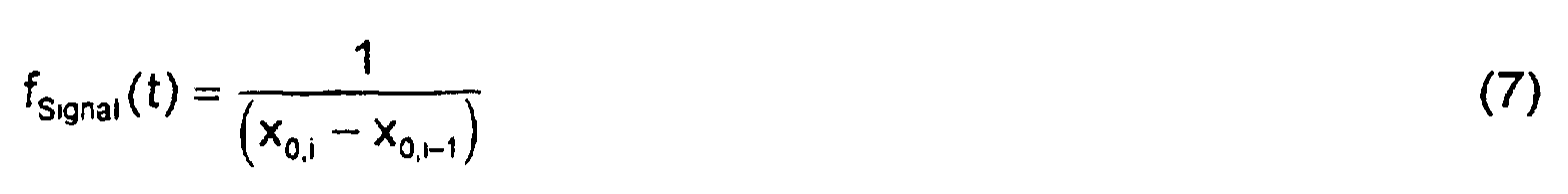
- the value x 2 corresponds to the current time and can therefore be replaced by t 2 .
- the frequency of the filtered signal follows from the reciprocal of the difference between two successive positive or negative zero crossings, equation 7, or from twice the value of half the period, equation 8.
- a warning algorithm can impermissible deviations of the resonance frequencies from a target value detect and issue a warning if the calculated frequency is one falls below a certain threshold.
- the warning level remains in all except for ABS standard braking Preserve driving situations. You also get an overview of how Deviations in speed detection over one wheel revolution are distributed. These deviations can be evaluated or recorded a change in wheel irregularity (e.g. wheel imbalance or stone in the Profile %) can be used.
- wheel irregularity e.g. wheel imbalance or stone in the Profile
Landscapes
- Engineering & Computer Science (AREA)
- Physics & Mathematics (AREA)
- Mechanical Engineering (AREA)
- General Physics & Mathematics (AREA)
- Transportation (AREA)
- Mathematical Physics (AREA)
- Measuring Fluid Pressure (AREA)
- Transmission And Conversion Of Sensor Element Output (AREA)
Description
Die Erfindung betrifft ein Verfahren zur Ermittlung von geschwindigkeitsunabhängigen
Frequenzen eines Nutzsignalanteils aus einem rechteckförmigen
Signal, dessen Frequenz proportional zur Geschwindigkeit ist, mittels
eines elektronischen Steuergeräts für Kraftfahrzeuge nach dem Oberbegriff
des Patentanspruchs 1.The invention relates to a method for determining speed-independent
Frequencies of a useful signal component from a rectangular one
Signal, the frequency of which is proportional to the speed, by means of
an electronic control unit for motor vehicles according to the preamble
of
Ein derartiges Verfahren ist beispielsweise aus der DE 43 30 617 A1 zur Ermittlung des Reifenluftdrucks bei Kraftfahrzeugen bekannt. Dem bekannten Verfahren liegt die Erkenntnis zugrunde, daß die Änderung der Federsteifigkeiten durch Änderung des Luftdruckes im Reifen eine Verschiebung der Eigenfrequenzen des Rad-Reifensystems in Kraftfahrzeugen bewirkt. Die Auswertung dieser Resonanzfrequenzen erfolgt üblicherweise mittels einer FFT (Fast Fourier Transformations)-Analyse.Such a method is known for example from DE 43 30 617 A1 Determination of tire air pressure in motor vehicles is known. The well-known The process is based on the knowledge that the change in spring stiffness a shift by changing the air pressure in the tire the natural frequencies of the wheel-tire system in motor vehicles. The These resonance frequencies are usually evaluated using a FFT (Fast Fourier Transformations) analysis.
Nachteilig bei dieser Methode ist die sehr zeit- und speicherplatzintensive FFT-Analyse. Weitere Probleme entstehen bei erhöhter Geschwindigkeit und auf ebener Fahrbahn. Auf Straßen mit starker vertikaler Anregung (Kopfsteinpflaster, schlechte Landstraße) können die Resonanzfrequenzen aus den berechneten FFT-Spektren abgeleitet werden. Auf ebenen Straßen verfälschen jedoch Fehler in der Geschwindigkeitserfassung mittels ABS-Raddrehzahlsignalen diese Spektren. Die nicht zu vermeidenden Fertigungstoleranzen der ABS-Impulsräder (Geberräder) verursachen bei der Transformation der Zeitsignale in den Frequenzbereich Resonanzpegel, die mit der Drehgeschwindigkeit des Rades oder einer höheren Ordnung davon übereinstimmen. Ebenso verfälschen Unwuchten am Rad oder an den Wellen der angetriebenen Räder die Ermittlung der durch den Reifenluftdruck bestimmten Resonanzfrequenzen der ABS-Raddrehzahlsignale.The disadvantage of this method is that it is very time and memory intensive FFT analysis. Other problems arise with increased speed and on a level road. On roads with strong vertical excitation (Cobblestones, bad country road) the resonance frequencies can be derived from the calculated FFT spectra. On flat roads however, falsify errors in speed detection using ABS wheel speed signals these spectra. The unavoidable manufacturing tolerances the ABS impulse wheels (encoder wheels) cause during the transformation of the time signals in the frequency domain resonance level with the rotational speed of the wheel or a higher order thereof to match. Imbalances on the wheel or on the shafts also falsify of the driven wheels the determination by the tire air pressure certain resonance frequencies of the ABS wheel speed signals.
In der Patentschrift EP 0 363 014 wird ein Verfahren vorgestellt, womit mit Hilfe eines Kraftsensors eine Unwucht an den Vorderrädern festgestellt werden kann. Das in dieser Patentschrift EP 0 363 014 vorgestellte Verfahren benötigt zusätzliche Kraftsensoren und ist nicht in der Lage, eine Aussage bezüglich der Hinterräder zu machen.In the patent EP 0 363 014 a method is presented, with which With the help of a force sensor, an imbalance on the front wheels can be determined can. The method presented in this patent EP 0 363 014 requires additional force sensors and is unable to make a statement regarding the rear wheels.
Nach US-A-5 541 859 können für jeden Zahn eines Geschwindigkeitssensors Korrekturfaktoren bestimmt werden, wobei eine Mittelwertbildung über eine volle Umdrehung erfolgt.According to US-A-5 541 859 a speed sensor can be used for each tooth Correction factors are determined, with averaging over a full Revolution takes place.
Es ist Aufgabe der Erfindung, ein Verfahren eingangs genannter Art derart zu verbessern, daß systematische Fehler bei der Erfassung eines Geschwindigkeitssignals mittels Drehzahlsensoren ermittelt und eliminiert werden, um die Ermittlung der Frequenz(en) des Nutzsignalanteils des Geschwindigkeitssignals zu ermöglichen.It is an object of the invention to provide a method of the type mentioned at the outset improve that systematic error in the detection of a speed signal determined and eliminated by means of speed sensors in order the determination of the frequency (s) of the useful signal component of the speed signal to enable.
Diese Aufgabe wird durch die kennzeichnenden Merkmale des Patentanspruchs
1 gelöst.This object is achieved by the characterizing features of the
Mit der erfindungsgemäßen Korrekturmethode des Drehzahl- bzw. Geschwindigkeitssignals können zum einen die Toleranzen und Teilungsfehler des Geberrades (z.B. ABS-Impulsrad) und zum anderen eine Exzentrizität des Drehlagers (z. B. Radlagers) oder der Antriebswelle oder eine Unwucht (z. B. am Rad) erfaßt werden. Dabei werden folgende mit jeder Umdrehung wiederkehrende Fehler eliminiert: zum einen die bei jeder Umdrehung am gleichen Ort kurzzeitig auftretenden extremen Veränderungen im Geschwindigkeitssignal (z. B. Teilungsfehler) und zum anderen die zyklischen, sich über eine ganze Umdrehung erstreckenden Änderungen im Geschwindigkeitssignal (z. B. Unwucht).With the correction method of the speed or speed signal according to the invention can tolerances and division errors of the encoder wheel (e.g. ABS pulse wheel) and secondly an eccentricity of the pivot bearing (e.g. wheel bearing) or the drive shaft or an imbalance (e.g. on the wheel). Doing the following with every revolution recurring errors eliminated: on the one hand, with each revolution on same place briefly occurring extreme changes in the speed signal (e.g. division errors) and secondly the cyclical, changes in the speed signal extending over an entire revolution (e.g. unbalance).
Eine vorteilhafte Weiterbildung der Erfindung ist der Gegenstand des Patentanspruchs
2. Hierdurch wird nach Eliminierung der genannten Fehler ein
besonders einfaches Verfahren zur Auswertung der Frequenzen des Nutzsignalanteils
geschaffen.An advantageous development of the invention is the subject of the
Das erfindungsgemäße Verfahren wird bevorzugt zur Schätzung des Reifenluftdrucks durch Ermittlung der Resonanzfrequenzen im Rad-Reifen-System eines Fahrzeuges verwendet. Die Erfindung wird am Beispiel dieser Anwendung näher erläutert. Das rechteckförmige Signal, dessen Frequenz proportional zur Geschwindigkeit ist, wird hierbei vorzugsweise mit einem Geberrad in Form eines 48 Zähne aufweisenden ABS-Impulsrades erzeugt. Im ff. wird das rechteckförmige Signal, dessen Frequenz proportional zur Geschwindigkeit ist, kurz rechteckförmiges Geschwindigkeitssignal genannt. Eine übliche Methode zur Erfassung des Geschwindigkeitssignals ist in Fig. 2 dargestellt. Ein induktiver Drehzahlsensor tastet die Zähne des Geberrades ab und erzeugt ab einer bestimmten Drehzahl ein sinusförmiges Signal S1. Dieses wird im Steuergerät oder bereits im Sensor selbst in ein rechteckförmiges Geschwindigkeitssignal S2 umgewandelt. Zur Messung der Dauer jedes einem Zahn zugeordneten Impulses, vorzugsweise von einer steigenden (oder fallenden) Flanke zur nächsten steigenden (oder fallenden) Flanke des Signals S2, läuft ein Zähler (Signal S3) mit, der der Dauer des Impulses einen Zählerstand bzw. Zahnwert zuordnet. Von einem derartigen Verfahren wird zur Erläuterung der Erfindung im folgenden ausgegangen.The method according to the invention is preferred for estimating the tire air pressure by determining the resonance frequencies in the wheel-tire system of a vehicle used. The invention is based on the example of this application explained in more detail. The rectangular signal whose frequency is proportional speed, is preferably done with an encoder wheel produced in the form of an ABS pulse wheel with 48 teeth. In the ff the rectangular signal whose frequency is proportional to the speed is called a rectangular speed signal for short. A common one The method for detecting the speed signal is shown in FIG. 2. An inductive speed sensor scans and generates the teeth of the encoder wheel from a certain speed a sinusoidal signal S1. This is in the control unit or already in the sensor itself in a rectangular Speed signal S2 converted. To measure the duration of each one Tooth-assigned pulse, preferably from a rising (or falling) edge to the next rising (or falling) edge of the signal S2, a counter (signal S3) runs along with the duration of the pulse Allocates meter reading or tooth value. From such a process started to explain the invention in the following.
Die Möglichkeit der Auswertung der Resonanzfrequenzen ist stark abhängig von der Anregung der Reifenschwingungen. Bei einem System, das auf einer Signalauswertung im Frequenzbereich basiert, muß die Leistung des Nutzsignales (z. B. auszuwertende Resonanzfrequenzen) bedeutend größer sein als die des Störsignales (z. B. Frequenzen durch Fehler im Geberrad oder aufgrund von Reifenunförmigkeiten). Das Nutzsignal entspricht der (Rad-) Geschwindigkeitsänderung durch Fahrbahnunebenheiten (die auszuwertenden Rad-Reifen-Resonanzschwingungen werden von der Straße angeregt), während das Störsignal der (Rad-) Geschwindigkeitsänderung durch Bauteiltoleranzen entspricht. Toleranzen führen auch bei konstanter Fahrgeschwindigkeit zu unterschiedlichen Abständen zwischen den Impulsflanken und täuschen somit falsche (Rad-) Geschwindigkeiten vor. Wenn die Anregung von der Straße ausreichend ist (Kopfsteinpflaster, schlechte Landstraße), kann eine Ermittlung der Resonanzfrequenzen im Signal erfolgen. Wenn die Anregung von der Straße in der gleichen Größenordnung des Störsignals liegt (Autobahn, Asphalt), verfälschen Fehler in der Geschwindigkeitserfassung die Auswertung. Darüber hinaus wird bei der Frequenzauswertung beispielsweise die Druckfrequenz des Rades und nicht die Rad-Reifen-Resonanzschwingung erfaßt.The possibility of evaluating the resonance frequencies is heavily dependent from the excitation of the tire vibrations. In a system based on a Signal evaluation based in the frequency domain, the performance of the Useful signals (e.g. resonance frequencies to be evaluated) significantly larger than that of the interference signal (e.g. frequencies due to errors in the encoder wheel or due to tire irregularities). The useful signal corresponds to the (Wheel) speed change due to uneven road surfaces (the ones to be evaluated Wheel-tire resonance vibrations are from the road excited), while the interference signal of the (wheel) speed change due to component tolerances. Tolerances lead to constant Driving speed at different distances between the pulse edges and thus pretend wrong (wheel) speeds. If the Suggestion from the street is sufficient (cobblestone, bad Country road), the resonance frequencies in the signal can be determined. If the excitation from the street is of the same order of magnitude Interference signal is (highway, asphalt), falsify errors in speed detection the evaluation. In addition, frequency analysis for example the pressure frequency of the wheel and not the Wheel-tire resonance vibration detected.
Bei der Erfassung der Geschwindigkeitssignale wird davon ausgegangen, daß alle Zähne des ABS-Impulsrades (Geberrades) die gleiche Breite aufweisen. Tatsächlich entstehen jedoch durch Fertigungstoleranzen, Schweißnahtbreite und -dicke, Grate der Fertigung, Verformung bei der Montage, Korrosion und Materialinhomogenitäten unterschiedliche Zahnbreiten. Eine Verbesserung kann zwar durch eine Nachbehandlung erreicht werden, in der das ABS-Impulsrad nochmals abgeschliffen wird, aber die für hochfrequente Auswertung notwendige Genauigkeit wird dadurch nicht erreicht. Für die Funktion der Radschlupfregelsysteme sind die Bauteiltoleranzen noch ausreichend. Die relative Abweichung durch einen derartigen Fehler nimmt bei höheren Geschwindigkeiten zu, da die Geschwindigkeit den reziproken Wert der gemessenen Dauer darstellt.When recording the speed signals, it is assumed that all teeth of the ABS pulse wheel (encoder wheel) have the same width. In fact, however, due to manufacturing tolerances, weld seam width and thickness, burrs of production, deformation during assembly, Corrosion and material inhomogeneities different tooth widths. A Improvement can be achieved by post-treatment in which the ABS pulse wheel is ground again, but for high-frequency ones The necessary accuracy of evaluation is not achieved. For the Function of the wheel slip control systems, the component tolerances are still sufficient. The relative deviation from such an error increases higher speeds because the speed is the reciprocal the measured duration.
Der zweite Grund, warum nicht alle erfaßten Zähne gleiche Zahnwerte bzw. Zählerstände aufweisen, liegt darin, daß immer eine Radungleichförmigkeit vorhanden ist, z.B. Unwucht, Exzentrizität des Radlagers oder der Antriebswelle und Verformung bei der Montage.The second reason why not all teeth recorded have the same tooth values or Have meter readings is that there is always a wheel non-uniformity is present, e.g. Imbalance, eccentricity of the wheel bearing or the drive shaft and deformation during assembly.
Das erfindungsgemäße Verfahren nützt das systematische Wiederkehren der Fehler (Teilungsfehler der Geberradzähne, Unwucht durch Radungleichförmigkeiten) aus, um diese zu eliminieren. Für jeden Zahn des Impulsrades wird der Fehler gelernt, den er gegenüber einem Sollwert (Mittelwert) aufweist. Die so ermittelten Faktoren dienen jeweils der Korrektur der gemessenen Werte.The method according to the invention uses systematic recurrence the error (pitch error of the encoder wheel teeth, unbalance due to wheel irregularities) to eliminate them. For each tooth of the impulse wheel the error is learned that it has compared to a target value (mean value). The factors determined in this way serve to correct the measured values Values.
In der Zeichnung ist ein Ausführungsbeispiel der Erfindung dargestellt. Es zeigen
- Fig. 1
- ein Gesamtsystem, in dem das erfindungsgemäße Verfahren vorzugsweise realisiert wird,
- Fig. 2
- eine übliche Methode als Beispiel zur Erfassung des Geschwindigkeitssignals
- Fig.3
- die durch die erfindungsgemäße Korrekturmethode erhaltenen zahnbezogenen Korrekturfaktoren,
- Fig. 4
- und Fig. 5 das Prinzip der Korrekturmethode und
- Fig. 6
- die Ermittlung einer Frequenz des Nutzsignalanteils (Resonanzfrequenz) durch Auswertung der Nulldurchgänge nach Eliminierung der zyklischen Fehler und nach einer Bandpaßfilterung
- Fig. 1
- an overall system in which the method according to the invention is preferably implemented,
- Fig. 2
- a common method as an example of acquiring the speed signal
- Figure 3
- the tooth-related correction factors obtained by the correction method according to the invention,
- Fig. 4
- 5 shows the principle of the correction method and
- Fig. 6
- the determination of a frequency of the useful signal component (resonance frequency) by evaluating the zero crossings after eliminating the cyclical errors and after bandpass filtering
In Fig. 1 ist ein elektronischen Steuergerät 1, vorzugsweise ein Steuergerät
für Bremssysteme (z. B. ABS/ASC) in Kraftfahrzeugen dargestellt, das als
Eingangssignal das Geschwindigkeitssignal S1 (Fig. 2) eines Drehzahlsensors
2 erhält, der mit einem eine bestimmte Anzahl (z. B. 48) von äquidistanten
Zähnen aufweisenden Geberrad (z. B. ABS-Impulsrad, Fig. 2) zusammenwirkt.
Im Reckteckimpulsumformer 3 wird aus dem sinusförmigen Signal
S1, dessen Frequenz proportional zur Geschwindigkeit ist (kurz sinusförmiges
Geschwindigkeitssignal S1 genannt), ein rechteckförmiges Geschwindigkeitssignal
S2 erzeugt. Der Rechteckimpulsformer 3 kann auch im Sensor
2 enthalten sein. Der Rechteckimpulsformer 3 ist mit einer Zählereinheit 4
(vgl. auch Signal S3, Fig. 2) verbunden, die die Dauer jedes Impulses des
Geschwindigkeitssignals S2 in Form eines Zahnwertes bzw. Zählerstandes
an die Korrektureinheit 5 übermittelt. In der Korrektureinheit 5 wird die Korrekturmethode
des erfindungsgemäßen Verfahrens durchgeführt. Ausgangssignal
der Korrektureinheit 5 ist ein durch das Lernen von Korrekturfaktoren
von Fehlern, die über eine Umdrehung periodisch auftreten, bereinigtes
Geschwindigkeitssignal. Dieses bereinigte Geschwindigkeitssignal enthält
noch die geschwindigkeitsunabhängigen Frequenzen des Nutzsignalanteils,
im vorliegenden Beispiel die Resonanzfrequenzen des Radsystems.
Um diese Resonanzfrequenzen auszuwerten, wird das bereinigte Geschwindigkeitssignal
über den Bandpaßfilter 6 zur Frequenzauswertungseinheit
7 weitergeführt. In der Frequenzauswertungseinheit 7 wird durch Auswertung
der Nulldurchgänge x0,i des gefilterten Geschwindigkeitssignals vgefiltert
die Ist-Resonanzfrequenz des Nutzsignalanteils sowie die Abweichung
dieser Ist-Resonanzfrequenz von einer vorgegebenen Soll-Resonanzfrequenz
ermittelt. In der Zuordnungseinheit 8 wird in Abhängigkeit
von der ermittelten Abweichung eine Änderung des Reifenluftdruckes p geschätzt
und beispielsweise einer hier nicht dargestellten Anzeige- oder Warneinheit
übermittelt. 1 shows an
In Fig. 3 sind die durch die erfindungsgemäße Korrekturmethode für alle 48 Zähne des Geberrades erhaltenen Korrekturwerte bzw. Korrekturfaktoren dargestellt. Durch den dem Zahn 15 zugeordneten Korrekturwert ist ein Teilungsfehler F, der aufgrund einer ungleichmäßigen Zahnbreite (vgl. auch Signal S2 in Fig. 2) aufgetreten ist, eliminiert. Weiterhin ist durch die Korrekturfaktoren aller Zähne eine sich über eine Umdrehung erstreckende, beispielsweise sinusförmige Unwuchtschwingung, deren Frequenz geschwindigkeitsabhängig ist, eliminiert.3 shows the correction method for all 48 by the correction method according to the invention Correction values or correction factors obtained for teeth of the encoder wheel shown. A division error is caused by the correction value assigned to tooth 15 F, which due to an uneven tooth width (see also signal S2 in Fig. 2) has been eliminated. Furthermore, by the correction factors of all teeth extending over one revolution, for example sinusoidal unbalance vibration, the frequency of which depends on the speed is eliminated.
In Fig. 4 und 5 wird die Korrekturmethode zur Bestimmung der in Fig. 3 dargestellten Korrekturmethode näher erläutert.FIGS. 4 and 5 show the correction method for determining that shown in FIG. 3 Correction method explained in more detail.
Grundsätzlich wird die mittlere Geschwindigkeit erfaßt. Beispielsweise kann die mittlere Geschwindigkeit, d.h. der Mittelwert des Zählerstandes, eines Impulses vorher und eines Impulses nachher berechnet werden, wodurch zumindest ein Teilungsfehler erfaßt wird. Vorzugsweise werden jedoch die Zählerstände von einer Viertelumdrehung vorher und nachher verwendet, wodurch eine halbe Radumdrehung erfaßt wird. Dadurch können sowohl Teilungsfehler als auch Radunförmigkeitsfehler eliminiert werden. Vorteil hierbei ist, daß die Abweichungen von der mittleren Geschwindigkeit durch Fehler unabhängig von Teilabschnitten des Geberrades bzw. ABS-Impulsrades korrigiert werden. Abweichungen, die mit einer Radumdrehung periodisch sind, haben somit keinen Einfluß auf die zu berechnenden Geschwindigkeitswerte.Basically, the average speed is recorded. For example the average speed, i.e. the mean of the meter reading, one Pulse before and after a pulse are calculated, whereby at least one division error is detected. However, preferably Counter readings of a quarter turn used before and after, whereby half a wheel revolution is detected. This allows both Pitch errors as well as wheel irregularity errors can be eliminated. advantage here is that the deviations from the average speed Faults regardless of sections of the encoder wheel or ABS pulse wheel Getting corrected. Deviations occurring periodically with one wheel revolution are therefore have no influence on the speed values to be calculated.
In Fig. 4 und 5 wird davon ausgegangen, daß pro Radumdrehung jeder Zahn erfaßt und korrigiert wird. 4 and 5 it is assumed that each tooth per wheel revolution is recorded and corrected.
In Fig. 4 werden als Beispiele neun Abtastpunkte P9, die den Zählerständen bzw. den Zahnwerten von neun der 48 Zähne einer Umdrehung entsprechen, bei einer Umdrehung dargestellt. Eine zahnbezogene Korrektur nach einer Abweichung ist mit Pfeilen gekennzeichnet.In Fig. 4 are nine sample points P9, the counter readings as examples or correspond to the tooth values of nine of the 48 teeth per revolution, represented at one revolution. A tooth-related correction after a deviation is marked with arrows.
Nach Fig. 5 wird jedem Zahn des Impulsrades ein Index i zugeordnet. Nach dem Überschreiten einer Sensoranspruchschwelle bei einer bestimmten Geschwindigkeit (z.B. v > 1 km/h) wird die Zuordnung aufgebaut. Wichtig dabei ist, daß die gelernten Korrekturwerte möglichst innerhalb weniger Sekunden vorliegen, wodurch die Erkennung eines Druckabfalls schnell sichergestellt werden kann.5, an index i is assigned to each tooth of the pulse wheel. The assignment is established after a sensor threshold has been exceeded at a certain speed (eg v> 1 km / h). It is important that the learned correction values are available within a few seconds if possible, so that the detection of a pressure drop can be quickly ensured.
Für eine mögliche Auslegungsform des Verfahrens werden jeweils der aktuelle
und die letzten 24 erfaßten Zählerstände entsprechend einer halben
Radumdrehung verwendet. Es wird vorausgesetzt, daß die Korrekturwerte
aller Zähne jede Umdrehung neu berechnet werden und es wird die Annahme
getroffen, daß sich in dem betrachteten kurzen Zeitintervall die Fahrzeuglängsbeschleunigung
nur geringfügig ändert. Zum Zeitpunkt des aktuell
gemessenen Zählerstandes τ i (z. B. auch P5; P6; P7; P8; P9, Fig. 4) wird
jeweils der Korrekturfaktor ki-12 zum vorher gemessenen Zählerstand τ i-12 (z.
B. auch P3; P4; P5; P6; P7, Fig. 4) berechnet, welcher den Zählerstand einer
Viertelradumdrehung vorher darstellt. Der korrigierte Zählerstand ti-12
wird mit Gleichung 1 bestimmt:
Die Berechnung der Korrekturfaktoren ki folgt aus der linearen Darstellung
des Geschwindigkeitsverlaufes (Fig. 5) zwischen dem mit dem in dieser Radumdrehung
erfaßten Korrekturfaktor korrigierten Zahnwert ti-24 (z. B. auch
P1; P2; P3; P4; P5, Fig. 4) und dem mit dem aus der vorigen Umdrehung
berechneten Korrekturfaktor korrigierten Zahnwert ti , Gleichung 2. Zwischen
den Stützpunkten i und i-24 wird ein linearer Verlauf gebildet. Der erfaßte
Zählerstand i-12 wird gerade auf die lineare Linie zu diesem Abtastpunkt
gelegt. Der dafür benötigte Korrekturfaktor κ i-12 wird von der Gleichung 2 berechnet.
Die beiden Zeitabschnitte Δta und Δtb werden jeweils mit Gleichung 3 berechnet.
Nach der Berechnung aller Korrekturfaktoren für jeden Zahn i des Geberrades
folgt beispielsweise eine Filterung der Korrekturfaktoren, um den Einfluß
der Fahrzeugbeschleunigung (d.h. kein linearer Verlauf der Gerade in Fig. 5)
und des Straßenprofils zu vermindern. Dieses Filter berechnet einen gewichteten
Mittelwert zwischen den Korrekturfaktoren der momentanen und vorherigen
Umdrehung, Gleichung 4.
Während der Laufzeit des Verfahrens wird der Faktor a angepaßt. Am Anfang sorgt ein kleiner Wert a für das schnelle Einschwingen auf den richtigen k-Wert; nach einiger Zeit wird der Faktor a vergrößert, wodurch das Nutzsignal weniger gefiltert und die Auflösung und Genauigkeit der Resonanzfrequenzberechnung gesteigert wird. Die Korrekturfaktoren werden laufend aktualisiert, da diese geschwindigkeitsabhängig sind.The factor a is adjusted during the running time of the method. In the beginning, a small value a ensures that the correct k value settles quickly; after a while the factor a is increased, which means that the useful signal is less filtered and the resolution and accuracy of the resonance frequency calculation is increased. The correction factors are continuously updated because they are speed-dependent.
Wenn die berechneten Korrekturfaktoren in einem Bild dargestellt werden, bekommt man einen Überblick, wie sich die Abweichungen der erfaßten Zählerstände über eine Radumdrehung verhalten. Fig. 3 zeigt die ermittelten Korrekturfaktoren nach beispielsweise zehn Radumdrehungen. Deutlich sichtbar ist der mit einer Umdrehung korrespondierende Verlauf der Abweichungen (F und Schwingung über eine Umdrehung). In der Initialisierungsphase (z.B. am Bandende oder nach Neumontage und Auswuchten des Rades) werden die Teilungsfehler, Exzentrizität des Impulsrades, des Radlagers und der Antriebswelle, sowie die Verformung bei der Montage als gesamtes Bild erfaßt und abgespeichert. Gravierende Änderungen dieses Bildes oder Unterschreiten einer festgelegten Schwelle der Korrelationsfunktion zwischen momentan erfaßtem und abgespeichertem Zustand können verwendet werden, um eine Unwucht oder eine andere Ungleichförmigkeit am Rad fest zu stellen. Ein Warnalgorithmus kann unzulässige Abweichungen dieses Bildes von einem Sollbild detektieren und eine Warnung ausgeben, falls die Abweichungen eine bestimmte Korrelationsschwelle unterschreitet.If the calculated correction factors are shown in an image, you get an overview of how the deviations of the recorded Counter readings behave over one wheel revolution. Fig. 3 shows the determined Correction factors after, for example, ten wheel revolutions. Clear the course of the deviations corresponding to one revolution is visible (F and vibration over one revolution). In the initialization phase (e.g. at the end of the line or after reassembly and balancing the wheel) the pitch errors, eccentricity of the impulse wheel, the wheel bearing and the drive shaft, as well as the deformation during assembly as a whole Image captured and saved. Serious changes to this picture or falling below a specified threshold of the correlation function between the currently recorded and saved state can be used to avoid an imbalance or other irregularity Lock the wheel. A warning algorithm can cause impermissible deviations detect this image from a target image and issue a warning, if the deviations fall below a certain correlation threshold.
Nach Fig. 5 wird bei einer Geschwindigkeit von 30 km/h in jedem Abtastzyklus, T = 5 ms, genau ein Zahnwert τ i erfaßt. Höhere Geschwindigkeiten bringen mehrere Zahnwerte pro Abtastzyklus. Die Genauigkeit des Verfahrens wird bei höheren Geschwindigkeiten von einer gewichteten Mittelwertbildung der innerhalb eines Abtastzyklus erfaßten korrigierten Zahnwerte gesteigert.5, exactly one tooth value τ i is recorded at a speed of 30 km / h in each sampling cycle, T = 5 ms. Higher speeds bring several tooth values per scanning cycle. The accuracy of the method is increased at higher speeds by a weighted averaging of the corrected tooth values recorded within a scanning cycle.
Nach der oben beschriebenen Korrektur der Raddrehzahlsignale werden die korrigierten und gemittelten Geschwindigkeitswerte bevorzugt mit einem Bandpaß gefiltert. Die Mittenfrequenz des Bandpasses entspricht in etwa der interessierenden Resonanzfrequenz.After the correction of the wheel speed signals described above, the corrected and averaged speed values preferably with a Bandpass filtered. The center frequency of the bandpass corresponds approximately to that resonant frequency of interest.
Eine sehr schnelle Methode zur Bestimmung einer Frequenz in einem gefilterten Signal ist die Auswertung der Periodendauer. Die Zeit zwischen zwei Nulldurchgängen (x0,i) (Vorzeichenwechsel des Signals) wird berechnet, wobei deren reziproker Wert der Frequenz des Signals entspricht. Wenn sich das Vorzeichen von beispielsweise einem negativen Wert in einen positiven Wert ändert, wird die Zeit, die dem Nulldurchgang entspricht, mit einer linearen Beziehung annähernd berechnet (Fig. 6). Es gibt verschiedene Möglichkeiten um die richtige Signalfrequenz zu erfassen: man wertet nur positive Nulldurchgänge aus (eine Periode), man wertet nur negative Nulldurchgänge aus (eine Periode), man bildet zwischen diesem positiven und negativen Nulldurchgang einen Mittelwert oder man wertet die Zeit zwischen einem negativen-positiven und positiven-negativen Nulldurchgang aus (halbe Periode).A very quick method of determining a frequency in a filtered signal is to evaluate the period. The time between two zero crossings (x 0, i ) (change of sign of the signal) is calculated, the reciprocal value of which corresponds to the frequency of the signal. When the sign changes from a negative value to a positive value, for example, the time corresponding to the zero crossing is approximately calculated with a linear relationship (Fig. 6). There are various ways to record the correct signal frequency: you only evaluate positive zero crossings (one period), you only evaluate negative zero crossings (one period), you average between this positive and negative zero crossing or you evaluate the time between one negative-positive and positive-negative zero crossing off (half period).
In Fig. 6 ist dargestellt, wie die Beziehung zwischen den diskreten Meßpunkten
((x1,y1) und (x2,y2)) und dem Nulldurchgang (x0,i,y0) abgeleitet werden
kann. Für den Nulldurchgang muß gelten, daß der y-Wert gleich Null ist.
Daraus ergibt sich die Gleichung 5.
Durch Lösen der rechten Gleichung, kann man eine Beziehung aufstellen,
woraus der Zeitpunkt des Nulldurchganges bestimmt wird, siehe Gleichung
6.
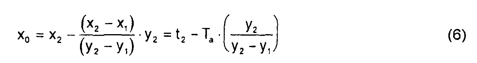
Der Wert x2 entspricht dem aktuellen Zeitpunkt und kann deswegen durch t2
ersetzt werden. Die Frequenz des gefilterten Signals folgt aus dem reziproken
Wert der Differenz zwischen zwei aufeinanderfolgenden positiven bzw.
negativen Nulldurchgängen, Gleichung 7, oder aus dem doppelten Wert der
halben Periode, Gleichung 8.

Nach jedem Nulldurchgang steht somit sofort ein aktueller Frequenzwert als Zeitsignal zur Weiterverarbeitung zur Verfügung. Ein Warnalgorithmus kann unzulässige Abweichungen der Resonanzfrequenzen von einem Sollwert detektieren und eine Warnung ausgeben, falls die berechnete Frequenz eine bestimmte Schwelle unterschreitet.After each zero crossing there is a current frequency value as Time signal available for further processing. A warning algorithm can impermissible deviations of the resonance frequencies from a target value detect and issue a warning if the calculated frequency is one falls below a certain threshold.
Mit den oben beschriebenen Verfahren kann ein kostengünstiges Reifenluftdrucküberwachungssystem dargestellt werden, welches keine zusätzliche Sensorik (z.B. Drucksensoren) benötigt und trotzdem die erforderliche Genauigkeit und Zuverlässigkeit von direkter Druckmessung bringt. Die Verfahren sind zudem unabhängig von Toleranzen der ABS-Sensorik bzw. der damit verbunden Bauteile. Selbst auf sehr ebenen Fahrbahnen ohne ersichtliche Unebenheiten lassen sich aus den ABS-Signalen die interessierenden (z.B. durch den Reifenluftdruck beeinflußten) Resonanzfrequenzen ermitteln. With the methods described above, an inexpensive tire air pressure monitoring system can are shown, which no additional Sensor technology (e.g. pressure sensors) is required and nevertheless the required accuracy and reliability of direct pressure measurement. The proceedings are also independent of the tolerances of the ABS sensors or related components. Even on very flat roads with no apparent Bumps can be identified from the ABS signals Determine resonance frequencies (e.g. influenced by tire air pressure).
Die Warnschärfe bleibt somit außer bei ABS-Regelbremsungen in allen Fahrsituationen erhalten. Zusätzlich bekommt man einen Überblick, wie die Abweichungen der Geschwindigkeitserfassung über eine Radumdrehung verteilt sind. Diese Abweichungen können zum Auswerten oder Erfassen einer Änderung in der Radungleichförmigkeit (z.B. Radunwucht oder Stein im Profil...) verwendet werden.The warning level remains in all except for ABS standard braking Preserve driving situations. You also get an overview of how Deviations in speed detection over one wheel revolution are distributed. These deviations can be evaluated or recorded a change in wheel irregularity (e.g. wheel imbalance or stone in the Profile ...) can be used.
Vorteile gegenüber dem in der Patentschrift EP 0 363 014 beschriebenen Verfahren liegen darin, daß keine zusätzlichen Kraftsensoren benötigt werden, falls auf bereits vorhandene ABS-Sensorik zurückgegriffen werden kann und daß ebenfalls eine (Änderung der) Ungleichförmigkeit an den Hinterrädern festgestellt werden kann.Advantages over that described in the patent specification EP 0 363 014 The method is that no additional force sensors are required, if existing ABS sensors are used can and that also a (change in) non-uniformity on the rear wheels can be determined.
Claims (2)
- A method in motor vehicles for determining speed-independent frequencies, especially resonance frequencies, of a usage signal portion of a rectangular speed signal (S2) generated by means of a rotational speed sensor (2) cooperating with a sensor wheel comprising a specific number (48) of approximately equidistant teeth, characterised in that, by means of an electronic control device (1),the duration or the counter reading of each pulse (i) of the rectangular speed signal (S2) is measured,at the instant of the currently measured counter reading (τi) the respective correction factor (ki-12) to the previously measured counter reading (τi-12) is calculated showing the counter reading of a quarter wheel rotation,the corrected counter reading (ti-12) is determined with the following equation:the correction factors (ki) are calculated from the linear view of the speed curve between the tooth value (ti-24) corrected with the correction factor detected in this wheel rotation and the tooth value (ti) corrected with the correction factor calculated from the previous rotation,a linear course is formed between the set points i and i-24 and the detected counter reading i-12 is placed just on the linear line to this scanning point andthe correction factor (ki-12) necessary for this is corrected by the following equation:wherein the two time portions Δta and Δtb are calculated with the following equation:
- A method according to claim 1, characterised in that after calculating all the correction factors for each tooth i of the sensor wheel a filtering of the correction factors follows in that a weighed average value is formed between the correction factors of the instantaneous and previous rotation according to the following equation:
Applications Claiming Priority (2)
| Application Number | Priority Date | Filing Date | Title |
|---|---|---|---|
| DE19735313 | 1997-08-14 | ||
| DE19735313A DE19735313B4 (en) | 1997-08-14 | 1997-08-14 | Method for determining speed-independent frequencies of a useful signal component |
Publications (3)
| Publication Number | Publication Date |
|---|---|
| EP0902292A2 EP0902292A2 (en) | 1999-03-17 |
| EP0902292A3 EP0902292A3 (en) | 1999-08-11 |
| EP0902292B1 true EP0902292B1 (en) | 2003-12-10 |
Family
ID=7839010
Family Applications (1)
| Application Number | Title | Priority Date | Filing Date |
|---|---|---|---|
| EP98112646A Expired - Lifetime EP0902292B1 (en) | 1997-08-14 | 1998-07-08 | Method for correcting the signal of a speed sensor |
Country Status (2)
| Country | Link |
|---|---|
| EP (1) | EP0902292B1 (en) |
| DE (2) | DE19735313B4 (en) |
Cited By (1)
| Publication number | Priority date | Publication date | Assignee | Title |
|---|---|---|---|---|
| CN106680531A (en) * | 2017-01-23 | 2017-05-17 | 中国核动力研究设计院 | Pump speed measuring device in high reliability nuclear power field |
Families Citing this family (15)
| Publication number | Priority date | Publication date | Assignee | Title |
|---|---|---|---|---|
| DE10148093A1 (en) | 2001-09-28 | 2003-04-17 | Bayerische Motoren Werke Ag | Wheel monitoring involves determining correction factor from deviation between current value and respective mean, adapting correction step size to error order of fault |
| GB0129446D0 (en) * | 2001-12-08 | 2002-01-30 | Lucas Industries Ltd | Angular velocity sensor |
| DE102004037283B4 (en) | 2003-08-15 | 2018-04-05 | Continental Teves Ag & Co. Ohg | Method for distinguishing imbalances on a rim and / or a tread of a vehicle wheel |
| EP1672372A4 (en) * | 2003-09-11 | 2010-01-06 | Nsk Ltd | Rotation speed detection device and rolling bearing unit load measurement device |
| CN103105503B (en) * | 2012-12-13 | 2014-07-30 | 中国北车集团大连机车车辆有限公司 | Detection method used for locomotive traction motor speed signals and based on magnetoelectric sensor |
| DE102013015705B4 (en) * | 2013-09-20 | 2019-12-05 | Audi Ag | Method for determining a current position of a motor vehicle in a geodetic coordinate system and motor vehicle |
| DE102014214538B4 (en) | 2014-07-24 | 2025-08-14 | Robert Bosch Gmbh | Method for facilitating the removal of objects adhering to motor vehicle tires |
| US10254129B2 (en) | 2015-02-27 | 2019-04-09 | Infineon Technologies Ag | Low noise zero crossing detection for indirect tire pressure monitoring |
| DE102016201331A1 (en) | 2016-01-29 | 2017-08-03 | Robert Bosch Gmbh | Method and device for detecting the azimuthal angular position of a wheel imbalance in a wheel on a vehicle |
| GB2555436B (en) * | 2016-10-27 | 2019-05-08 | Delphi Tech Ip Ltd | Method to determine tooth error in period of one or more teeth of a rotating toothed wheel |
| FR3066721B1 (en) * | 2017-05-23 | 2019-06-07 | Continental Automotive France | METHOD FOR IDENTIFYING AT LEAST ONE TRANSMITTER FOR MONITORING THE PRESSURE OF A TIRE OF A MOTOR VEHICLE BY ASSOCIATION WITH ONE OF THE WHEELS OF SAID MOTOR VEHICLE |
| KR102764291B1 (en) * | 2018-11-06 | 2025-02-07 | 현대자동차주식회사 | Apparatus and Method for estimating the resonant frequencies of a tire |
| DE102019204026A1 (en) | 2019-03-25 | 2020-10-01 | Robert Bosch Gmbh | Method and device for detecting a loosened wheel screw connection on a wheel |
| US11815426B2 (en) * | 2020-10-16 | 2023-11-14 | GM Global Technology Operations LLC | Robust tire/wheel vibration monitor system |
| CN115754336A (en) * | 2022-11-02 | 2023-03-07 | 国能(绥中)发电有限责任公司 | Method and system for processing rotating speed signal |
Family Cites Families (15)
| Publication number | Priority date | Publication date | Assignee | Title |
|---|---|---|---|---|
| DE2915815A1 (en) * | 1979-04-19 | 1980-11-06 | Bauknecht Gmbh G | DEVICE FOR DETECTING THE SPEED AND THE BALANCE OF AN AGGREGATE IN A HOUSING VIBRATINGLY |
| DE3425472A1 (en) * | 1984-07-11 | 1986-01-23 | Licentia Patent-Verwaltungs-Gmbh, 6000 Frankfurt | Method and device for digitally determining the number of revolutions of rotating bodies |
| DE3543058C2 (en) * | 1985-12-05 | 1997-02-13 | Teves Gmbh Alfred | Method and circuit arrangement for processing a sensor signal |
| JP2588219B2 (en) * | 1987-11-17 | 1997-03-05 | 日産自動車株式会社 | Apparatus for correcting detection value of vehicle speed sensor |
| US4907452A (en) * | 1988-10-05 | 1990-03-13 | Ford Motor Company | System for detecting rotational imbalance of vehicle roadwheels |
| DE3937403A1 (en) * | 1989-11-10 | 1991-05-16 | Porsche Ag | Monitoring functionality of motor vehicle chassis during travel - using microcomputer to process vibration detector signals to monitor wheel imbalance and shock absorber state |
| US5117681A (en) * | 1990-10-01 | 1992-06-02 | Ford Motor Company | Correction of systematic position-sensing errors in internal combustion engines |
| DE4208989A1 (en) * | 1992-03-20 | 1993-09-23 | Philips Patentverwaltung | METHOD FOR DETECTING AND COMPENSATING AN UNBALANCE IN A ROTOR DRIVED BY A MOTOR |
| US5541859A (en) * | 1993-03-23 | 1996-07-30 | Nippondenso Co., Ltd. | Speed detecting apparatus for rotating body |
| DE4330617A1 (en) * | 1993-09-09 | 1995-03-16 | Bayerische Motoren Werke Ag | Method for determining the pressure of the pneumatic tyres of vehicle wheels |
| DE4406606A1 (en) * | 1994-03-01 | 1995-09-07 | Audi Ag | Adaptation device for a sensor wheel on an internal combustion engine |
| GB9413677D0 (en) * | 1994-07-07 | 1994-08-24 | Lucas Ind Plc | Method of and apparatus for calibrating rotary position transducers |
| DE69510287T2 (en) * | 1994-09-09 | 2000-03-23 | Denso Corp., Kariya | Pneumatic tire pressure gauge |
| JP3175552B2 (en) * | 1995-08-04 | 2001-06-11 | 株式会社デンソー | Tire pressure estimation device |
| DE19540674C2 (en) * | 1995-10-31 | 1999-01-28 | Siemens Ag | Adaptation procedure for correcting tolerances of an encoder wheel |
-
1997
- 1997-08-14 DE DE19735313A patent/DE19735313B4/en not_active Expired - Fee Related
-
1998
- 1998-07-08 EP EP98112646A patent/EP0902292B1/en not_active Expired - Lifetime
- 1998-07-08 DE DE59810385T patent/DE59810385D1/en not_active Expired - Lifetime
Cited By (2)
| Publication number | Priority date | Publication date | Assignee | Title |
|---|---|---|---|---|
| CN106680531A (en) * | 2017-01-23 | 2017-05-17 | 中国核动力研究设计院 | Pump speed measuring device in high reliability nuclear power field |
| CN106680531B (en) * | 2017-01-23 | 2019-07-30 | 中国核动力研究设计院 | A kind of high reliability nuclear power field pump speed measuring device |
Also Published As
| Publication number | Publication date |
|---|---|
| EP0902292A2 (en) | 1999-03-17 |
| DE19735313A1 (en) | 1999-02-18 |
| DE59810385D1 (en) | 2004-01-22 |
| EP0902292A3 (en) | 1999-08-11 |
| DE19735313B4 (en) | 2008-02-07 |
Similar Documents
| Publication | Publication Date | Title |
|---|---|---|
| EP0902292B1 (en) | Method for correcting the signal of a speed sensor | |
| DE69400200T2 (en) | Method and device for estimating a disturbance acting on a frosted vehicle wheel on the basis of the angular speed of the wheel | |
| EP0933237B1 (en) | Method for monitoring the pressure of vehicle tyres | |
| EP0938987B1 (en) | Method and apparatus for monitoring the tyre pressure of motor vehicle wheels | |
| EP2250037B1 (en) | Method for determining the loading of a vehicle | |
| EP1646515B1 (en) | Method for determining internal pressure of a vehicle tyre | |
| DE602004013044T2 (en) | TRAIN STATION DETECTION APPARATUS AND METHOD IN A MOTOR VEHICLE | |
| DE3715007A1 (en) | METHOD AND DEVICE FOR DETERMINING THE COURSE OF A LAND VEHICLE | |
| WO1992008137A1 (en) | Circuit arrangement for preparing the output signal of a revolution speed sensor | |
| EP1708897B1 (en) | Tire pressure loss detection | |
| DE19540675C1 (en) | Torque estimation method using evaluation of internal combustion engine revolution rate for engine control | |
| DE69716542T2 (en) | Tire defect sensor | |
| DE19537257A1 (en) | Determining physical profile of road surface during movement of motor vehicle on road | |
| DE102009012128B4 (en) | A method of determining roughness of a road surface for a vehicle | |
| DE4035370A1 (en) | METHOD FOR DETERMINING THE LOCATION OF A LANDING VEHICLE | |
| EP1304576A2 (en) | Method for monitoring the state of the wheel of a motor vehicle | |
| EP1216177B1 (en) | Tire sensor | |
| EP1162443A2 (en) | Method and device for recognising damper damages | |
| DE19963751A1 (en) | Method for examining tires of vehicles while driving | |
| DE102017003442A1 (en) | Method for detecting the direction of travel of a vehicle | |
| EP3410081B1 (en) | Effective value determination of a machinery vibration measure | |
| WO2005123423A2 (en) | System for detecting an automotive tire pressure loss | |
| DE102005050206A1 (en) | Route or speed determination device e.g. for motor vehicle, has wheel having sensor for sensing number of revolutions for each 360 degrees and from number of revolutions impulses detected, distance and speed is derived | |
| DE102015212944A1 (en) | Method and device for determining rotational angular velocities and / or rotational angular positions of vehicle wheels of a motor vehicle, as well as for locating the installation positions of wheel units arranged on the vehicle wheels | |
| DE102007030432B4 (en) | Procedure for detecting the direction of rotation of an encoder |
Legal Events
| Date | Code | Title | Description |
|---|---|---|---|
| PUAI | Public reference made under article 153(3) epc to a published international application that has entered the european phase |
Free format text: ORIGINAL CODE: 0009012 |
|
| AK | Designated contracting states |
Kind code of ref document: A2 Designated state(s): DE FR GB |
|
| AX | Request for extension of the european patent |
Free format text: AL;LT;LV;MK;RO;SI |
|
| PUAL | Search report despatched |
Free format text: ORIGINAL CODE: 0009013 |
|
| AK | Designated contracting states |
Kind code of ref document: A3 Designated state(s): AT BE CH CY DE DK ES FI FR GB GR IE IT LI LU MC NL PT SE |
|
| AX | Request for extension of the european patent |
Free format text: AL;LT;LV;MK;RO;SI |
|
| RIC1 | Information provided on ipc code assigned before grant |
Free format text: 6G 01P 21/02 A, 6G 01P 3/489 B, 6G 01D 18/00 B, 6B 60C 23/06 B |
|
| 17P | Request for examination filed |
Effective date: 20000202 |
|
| AKX | Designation fees paid |
Free format text: DE FR GB |
|
| 17Q | First examination report despatched |
Effective date: 20020729 |
|
| GRAH | Despatch of communication of intention to grant a patent |
Free format text: ORIGINAL CODE: EPIDOS IGRA |
|
| GRAS | Grant fee paid |
Free format text: ORIGINAL CODE: EPIDOSNIGR3 |
|
| GRAA | (expected) grant |
Free format text: ORIGINAL CODE: 0009210 |
|
| AK | Designated contracting states |
Kind code of ref document: B1 Designated state(s): DE FR GB |
|
| REG | Reference to a national code |
Ref country code: GB Ref legal event code: FG4D Free format text: NOT ENGLISH |
|
| GBT | Gb: translation of ep patent filed (gb section 77(6)(a)/1977) |
Effective date: 20031210 |
|
| REF | Corresponds to: |
Ref document number: 59810385 Country of ref document: DE Date of ref document: 20040122 Kind code of ref document: P |
|
| ET | Fr: translation filed | ||
| PLBE | No opposition filed within time limit |
Free format text: ORIGINAL CODE: 0009261 |
|
| STAA | Information on the status of an ep patent application or granted ep patent |
Free format text: STATUS: NO OPPOSITION FILED WITHIN TIME LIMIT |
|
| 26N | No opposition filed |
Effective date: 20040913 |
|
| PGFP | Annual fee paid to national office [announced via postgrant information from national office to epo] |
Ref country code: GB Payment date: 20070726 Year of fee payment: 10 |
|
| PGFP | Annual fee paid to national office [announced via postgrant information from national office to epo] |
Ref country code: FR Payment date: 20070730 Year of fee payment: 10 |
|
| GBPC | Gb: european patent ceased through non-payment of renewal fee |
Effective date: 20080708 |
|
| REG | Reference to a national code |
Ref country code: FR Ref legal event code: ST Effective date: 20090331 |
|
| PG25 | Lapsed in a contracting state [announced via postgrant information from national office to epo] |
Ref country code: GB Free format text: LAPSE BECAUSE OF NON-PAYMENT OF DUE FEES Effective date: 20080708 |
|
| PG25 | Lapsed in a contracting state [announced via postgrant information from national office to epo] |
Ref country code: FR Free format text: LAPSE BECAUSE OF NON-PAYMENT OF DUE FEES Effective date: 20080731 |
|
| PGFP | Annual fee paid to national office [announced via postgrant information from national office to epo] |
Ref country code: DE Payment date: 20140725 Year of fee payment: 17 |
|
| REG | Reference to a national code |
Ref country code: DE Ref legal event code: R119 Ref document number: 59810385 Country of ref document: DE |
|
| PG25 | Lapsed in a contracting state [announced via postgrant information from national office to epo] |
Ref country code: DE Free format text: LAPSE BECAUSE OF NON-PAYMENT OF DUE FEES Effective date: 20160202 |