EP0902269A2 - Method for the determination of the immobilisation of colloid coating dispersions - Google Patents
Method for the determination of the immobilisation of colloid coating dispersions Download PDFInfo
- Publication number
- EP0902269A2 EP0902269A2 EP98114022A EP98114022A EP0902269A2 EP 0902269 A2 EP0902269 A2 EP 0902269A2 EP 98114022 A EP98114022 A EP 98114022A EP 98114022 A EP98114022 A EP 98114022A EP 0902269 A2 EP0902269 A2 EP 0902269A2
- Authority
- EP
- European Patent Office
- Prior art keywords
- coating dispersion
- immobilization
- porous substrate
- colloidal
- measured
- Prior art date
- Legal status (The legal status is an assumption and is not a legal conclusion. Google has not performed a legal analysis and makes no representation as to the accuracy of the status listed.)
- Granted
Links
Images
Classifications
-
- G—PHYSICS
- G01—MEASURING; TESTING
- G01N—INVESTIGATING OR ANALYSING MATERIALS BY DETERMINING THEIR CHEMICAL OR PHYSICAL PROPERTIES
- G01N11/00—Investigating flow properties of materials, e.g. viscosity, plasticity; Analysing materials by determining flow properties
- G01N11/10—Investigating flow properties of materials, e.g. viscosity, plasticity; Analysing materials by determining flow properties by moving a body within the material
- G01N11/14—Investigating flow properties of materials, e.g. viscosity, plasticity; Analysing materials by determining flow properties by moving a body within the material by using rotary bodies, e.g. vane
-
- G—PHYSICS
- G01—MEASURING; TESTING
- G01N—INVESTIGATING OR ANALYSING MATERIALS BY DETERMINING THEIR CHEMICAL OR PHYSICAL PROPERTIES
- G01N33/00—Investigating or analysing materials by specific methods not covered by groups G01N1/00 - G01N31/00
- G01N33/26—Oils; Viscous liquids; Paints; Inks
- G01N33/32—Paints; Inks
-
- G—PHYSICS
- G01—MEASURING; TESTING
- G01N—INVESTIGATING OR ANALYSING MATERIALS BY DETERMINING THEIR CHEMICAL OR PHYSICAL PROPERTIES
- G01N33/00—Investigating or analysing materials by specific methods not covered by groups G01N1/00 - G01N31/00
- G01N33/34—Paper
Definitions
- the invention relates to a method for determining immobilization colloidal coating dispersions applied to a porous substrate the use of the method and devices for carrying it out of the procedure.
- Field of application is in particular the paper manufacturing, where the knowledge the immobilization of paper coating colors during the application process an important one on raw paper for the technical usability of new recipes Role play.
- the immobilization of colloidal coating dispersions is also up other areas of importance, for example for adhesives or mortar, the liquid phase of the coating dispersion not being limited to water have to be.
- a common method of characterizing immobilization is the so-called clay plate method (M. Baumeister and J. Weigl, Wienblatt for paper manufacture 108 (5) (1980), 145-151). After that, a drop a paper coating slip on an unglazed clay plate and with with a spatula until the mixture is firm. The time required is called the immobilization time.
- the method has the disadvantages that the immobilization is not under processing-relevant conditions is determined - the liquid-absorbing The substrate is specified, no defined layer thickness can be specified become - and the immobilization determination is subjective.
- the above method was carried out by the reflection measurement method [U.Beck et al., Kliblatt für Textilfabrikation 111 (16) (1983), 561-565)] automated and objectified.
- the experimental arrangement is represented by a Photodiode complements the temporal evolution of the intensity of the reflection of a beam of rays on the surface of the paper coating slip. Also however, this experimental arrangement does not simulate practical conditions.
- the amount of water penetrating a defined base paper in a certain time and under certain pressure is determined gravimetrically. It is therefore not the immobilization but the water loss through penetration into the base paper with which the immobilization is connected that is measured.
- the process simulates only a few practical conditions: ink and base paper are separated by a polycarbonate filter, there is no shear stress, and no process-relevant layer thickness is set.
- the object of the invention is therefore to provide a method according to which the immobilization of colloidal coating dispersions on application a porous substrate can be determined under conditions suitable for the Processing processes are relevant:
- the layer thickness of the coating dispersion as well as the shear stresses that occur during the coating process can be approximated to the practical conditions;
- the device to carry out the method is robust and easy to use, and the required technical equipment can be added as additional modules in commercially available Rotational rheometer can be integrated.
- the object is achieved according to the invention by a method for determination immobilization of colloidal coating dispersions during application on a porous substrate by viscosity measurement, after which on the porous substrate, which is a boundary surface of the measuring gap of a rheometer forms, the colloidal coating dispersion applied and the temporal Change in viscosity is measured.
- the viscosity measurement can be specified with a constant shear stress or shear rate.
- the method according to the invention is particularly suitable for characterization immobilization of paper coating slip by penetration of water in the base paper to be coated.
- the procedure is also suitable to characterize other colloidal coating dispersions, for example of adhesives or mortar.
- porous substrate e.g. clay plate, glass frit
- the layer thickness of the porous substrate and thus the height of the rheometer measuring gap can preferably be between 20 ⁇ m and 2mm, especially preferably between 50 ⁇ m and 500 ⁇ m.
- the Compressive stress can be approximated to the practical conditions.
- phase can also be determined by other known measuring methods, in particular can be tracked by dielectric and light spectroscopic methods.
- the time course of the change in viscosity becomes the same measured using a commercially available shear stress controlled rheometer is modified in such a way that the porous substrate by the Absorption of part of the liquid phase that causes immobilization, forms a boundary surface of the rheometer gap.
- Rheometers with plate-plate geometry are particularly suitable however, rheometer devices are also possible, which are a plate-cone or have a cylinder arrangement.
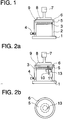
- a commercial, shear stress controlled rotary rheometer for example Bohlin R CS with a sample receiving or measuring gap in plate-plate geometry, is modified as follows (Figure 1): A cylindrical, metallic hollow body 2 is placed on the fixed rheometer base plate 1, the top surface of which consists of a perforated metal plate 3 there. In the outer surface of a nozzle 4 is embedded, which serves to connect a vacuum pump. The porous substrate 5, for example raw paper, is fastened on the perforated metal plate 3 with the aid of a suitable clamping ring 6. This porous substrate 5 now serves as the lower boundary surface of the measuring gap. The opposite boundary surface is a metal plate 8 connected to the drive and detection system 7 of the rheometer. The gap in between is filled with the colloidal coating dispersion 9 to be examined, for example with paper coating slip.
- the gap height can be between 20 microns and 2 mm, preferably between 50 and 500 ⁇ m can be varied.
- the water from the coating color 9 is absorbed by the base paper 5, preferably by applying a suitable negative pressure, especially in the Range from 200 to 500 mbar. This makes the coating color 9 similar as in the coating process in paper finishing, concentrated.
- a suitable negative pressure especially in the Range from 200 to 500 mbar.
- a constant shear stress preferably 0.1 to 1000 Pa, particularly preferably 10 to 100 Pa, measured.
- Vacuum By varying the specified shear stress and, if necessary, the Vacuum can simulate different coating conditions become.
- the gap is overfilled (see FIG. 1), so that paint can flow into the gap from the outside.
- the outer area of the measuring gap is therefore always wetter than the inside, ie the sample is inhomogeneous and the measured viscosities must be regarded as apparent or relative values.
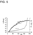
- the break point in the semi-logarithmic representation of the viscosity as a function of time (FIG. 3) is referred to as the immobilization point, the corresponding time as the immobilization time t imm .
- a solid-like filter cake with a residual water content of 15-20% is found in the inner area of the sample gap.
- the measurement method described above is not based on the characterization of the Immobilization of paper coating slip by penetration of water into it limited raw paper to be coated. Similarly, others (too non-aqueous) coating dispersions (e.g. adhesives, mortar) examined become.
- the respective substrate e.g. clay plate, Glass frit
- the respective substrate can be used as a rheometer base plate.
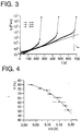
- Example 1 The device of Example 1 is improved by integrating one fiber optic scattered light measuring system according to EP-B1-0 472 899 in the perforated Metal plate 3 of the modified rheometer ( Figure 2). This will simultaneously with the viscosity determination, the measurement of the time course of the Water content possible.
- a broadband light source 10 preferably halogen light source
- an OH-poor quartz fiber preferably a fiber bundle 200 ⁇ m fibers
- light directed to the measuring point is scattered on the product, in the parallel receiving fibers are scattered back and to the detector 11 headed.
- the sensor tip 13 of the fiber optic scattered light measuring system protrudes through the perforated metal plate 3 and the porous substrate 5 into the colloid Coating dispersion 9.
- the absorption of the NIR radiation by the water is due to the Excitation of the 2nd harmonic of the OH vibration caused.
- the light becomes broadband to achieve the required signal level 1470 ⁇ 20 nm recorded.
- To calibrate the product spread without Water absorption is simultaneously a measurement in a near the absorption band lying but not absorbing wavelength range of Spectrum, preferably carried out at 1300 nm or 1700 nm. Around to be able to carry out measurements at several wavelengths at the same time, the light is not on the transmission side but on the detection side selected.
- the intensity of the light source at the selected wavelengths (here 1470 nm and 1700 nm). This can cause signal fluctuations due to the drift of the light source.
- the stability of the other components is guaranteed on site.
- the measuring area With a suitable drill guide around the 4 mm diameter as possible the measuring area is kept small, the drainage directly at the measuring point little handicapped. Because of the imprinted shear, the product lying on the wall in the plane of the porous substrate 5 Sensor tip 13 passed, with an averaging over the entire the corresponding circular ring is reached. At the The measuring point requires a suitable perforation of the paper to ensure the light to be able to couple directly into the coating dispersion 9.
- the measuring system has a modular structure. This allows the spectral range, Fiber material, evaluation algorithm and installation environment in one wide range quickly adapted to the requirements of new tasks become.
- Measured value acquisition takes place at a speed necessary for the examination of up to 30 measurements / second.
- the viscosity curves show a characteristic kink.
- a characteristic immobilization time t imm can be determined from the point of intersection of the tangents to the front or rear branch of the respective curves (see FIG. 3).
- the light intensity registered in the detector 11 is in the form of a voltage signal spent.
- the water content of the sample is related to the voltage difference ⁇ U linked which results from the different intensities of the light reflected at 1470 nm or 1700 nm.
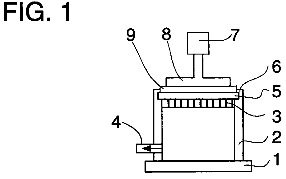
- the solids content F of the individual samples was determined as a function of the measured voltage difference ⁇ U plotted ( Figure 4).
- a calibration function valid for coating color B
- This function can be used to measure those measured during the drainage process Voltage differences ⁇ U can be converted into solid content values.
- the calibration function depends heavily on the device specifications and Every time the measurement setup is modified (aging / replacement of the halogen lamp, Change / drift of the measuring amplifier, etc.) can be determined again.
Landscapes
- Physics & Mathematics (AREA)
- Health & Medical Sciences (AREA)
- Life Sciences & Earth Sciences (AREA)
- Chemical & Material Sciences (AREA)
- Analytical Chemistry (AREA)
- Biochemistry (AREA)
- General Health & Medical Sciences (AREA)
- General Physics & Mathematics (AREA)
- Immunology (AREA)
- Pathology (AREA)
- Investigating Or Analysing Materials By Optical Means (AREA)
- Paper (AREA)
- Measuring Or Testing Involving Enzymes Or Micro-Organisms (AREA)
- Paints Or Removers (AREA)
- Application Of Or Painting With Fluid Materials (AREA)
- Investigating Or Analyzing Non-Biological Materials By The Use Of Chemical Means (AREA)
Abstract
Es wird ein Verfahren vorgeschlagen zur Bestimmung der Immobilisierung
einer kolloiden Beschichtungsdispersion, das auf ein poröses Substrat aufgetragen
wird, wonach auf das poröse Substrat, das eine Begrenzungsfläche
des Meßspalts eines Rheometers bildet, die kolloide Beschichtungsdispersion
aufgebracht und die zeitliche Änderung der Viskosität gemessen wird. Das
Verfahren eignet sich insbesondere zur Messung der Immobilisierung von
Papierstreichfarbe auf Rohpapier.
Description
Die Erfindung betrifft ein Verfahren zur Bestimmung der Immobilisierung kolloider Beschichtungsdispersionen, die auf ein poröses Substrat aufgetragen werden, die Verwendung des Verfahrens sowie Vorrichtungen zur Durchführung des Verfahrens.The invention relates to a method for determining immobilization colloidal coating dispersions applied to a porous substrate the use of the method and devices for carrying it out of the procedure.
Die Kenntnis der zeitlichen Veränderung von Eigenschaften kolloider Beschichtungsdispersionen während des Auftrags auf poröse Substrate ist eine wesentliche Voraussetzung für die Verbesserung der technischen Verarbeitbarkeit sowie die Optimierung neuer Rezepturen. Von besonderem Interesse ist in diesem Zusammenhang die Veränderung der Viskosität der kolloiden Beschichtungsdispersion während des Auftragvorganges und insbesondere die Kenntnis des Zeitpunkts, zu dem die Viskosität plötzlich ansteigt. Der Knickpunkt in der graphischen Darstellung der zeitabhängigen Viskositätsänderung wird als Immobilisierungspunkt, die entsprechende Zeit als Immobilisierungszeit bezeichnet. Als Immobilisierung wird der Zustand bezeichnet, bei dem aufgrund des erhöhten Feststoffgehaltes alle das Feststoffsystem betreffenden Fließ- und Transportprozesse unterbunden sind.Knowledge of the temporal change in properties of colloidal coating dispersions during application to porous substrates is one essential prerequisite for the improvement of the technical processability as well as the optimization of new recipes. Of special interest in this context is the change in the viscosity of the colloids Coating dispersion during the application process and especially the Knowledge of the point in time when the viscosity suddenly increases. Of the Break point in the graphical representation of the time-dependent change in viscosity is used as the immobilization point, the corresponding time as the immobilization time designated. Immobilization is the state where due to the increased solids content all the solids system relevant flow and transport processes are prevented.
Anwendungsgebiet ist insbesondere die Papierfabrikation, wo die Kenntnis der Immobilisierung von Papierstreichfarben während des Auftragsvorgangs auf Rohpapier für die technische Nutzbarkeit neuer Rezepturen eine bedeutende Rolle spielt. Field of application is in particular the paper manufacturing, where the knowledge the immobilization of paper coating colors during the application process an important one on raw paper for the technical usability of new recipes Role play.
Die Immobilisierung kolloider Beschichtungsdispersionen ist jedoch auch auf anderen Gebieten von Bedeutung, beispielsweise für Klebstoffe oder Mörtel, wobei die flüssige Phase der Beschichtungsdispersion nicht auf Wasser beschränkt sein muß.However, the immobilization of colloidal coating dispersions is also up other areas of importance, for example for adhesives or mortar, the liquid phase of the coating dispersion not being limited to water have to be.
Ein gebräuchliches Verfahren zur Charakterisierung der Immobilisierung ist die sogenannte Tonteller-Methode (M. Baumeister und J. Weigl, Wochenblatt für Papierfabrikation 108(5) (1980), 145-151). Danach wird ein Tropfen einer Papierstreichfarbe auf einen unglasierten Tonteller gegeben und mit einem Spatel so lange gerührt, bis die Masse fest ist. Die erforderliche Zeit wird als Immobilisierungszeit bezeichnet.A common method of characterizing immobilization is the so-called clay plate method (M. Baumeister and J. Weigl, Wochenblatt for paper manufacture 108 (5) (1980), 145-151). After that, a drop a paper coating slip on an unglazed clay plate and with with a spatula until the mixture is firm. The time required is called the immobilization time.
Das Verfahren hat die Nachteile, daß die Immobilisierung nicht unter verarbeitungsrelevanten Bedingungen bestimmt wird - das flüssigkeitsaufnehmende Substrat ist vorgegeben, es kann keine definierte Schichtdicke vorgegeben werden - und die Immobilisierungsbestimmung ist subjektiv.The method has the disadvantages that the immobilization is not under processing-relevant conditions is determined - the liquid-absorbing The substrate is specified, no defined layer thickness can be specified become - and the immobilization determination is subjective.
Das obengenannte Verfahren wurde durch das Reflexionsmessungsverfahren [U.Beck et al., Wochenblatt für Papierfabrikation 111(16) (1983), 561-565)] automatisiert und objektiviert. Die Versuchsanordnung wird durch eine Photodiode ergänzt, die die zeitliche Entwicklung der Intensität der Reflexion eines Strahlenbündels an der Oberfläche der Papierstreichfarbe mißt. Auch diese Versuchsanordnung simuliert jedoch nicht praxisrelevante Bedingungen.The above method was carried out by the reflection measurement method [U.Beck et al., Wochenblatt für Papierfabrikation 111 (16) (1983), 561-565)] automated and objectified. The experimental arrangement is represented by a Photodiode complements the temporal evolution of the intensity of the reflection of a beam of rays on the surface of the paper coating slip. Also however, this experimental arrangement does not simulate practical conditions.
Nach der Gradek-Methode (S.E. Sandas, P.J. Salminen, D.E Eklund, Tappi 72(12) (1989), 207-210) wird die in einer bestimmten Zeit und unter bestimmtem Druck ein definiertes Rohpapier penetrierende Wassermenge gravimetrisch bestimmt. Es wird somit nicht die Immobilisierung, sondern der Wasserverlust durch Penetration in das Rohpapier, mit dem die Immobilisierung verbunden ist, gemessen. Das Verfahren simuliert nur ansatzweise praxisrelevante Bedingungen: Farbe und Rohpapier sind durch ein Polycarbonat-Filter getrennt, es findet keine Scherbeanspruchung statt, und es wird keine prozeßrelevante Schichtdicke eingestellt.According to the Gradek method (SE Sandas, PJ Salminen, DE Eklund, Tappi 72 (12) (1989), 207-210), the amount of water penetrating a defined base paper in a certain time and under certain pressure is determined gravimetrically. It is therefore not the immobilization but the water loss through penetration into the base paper with which the immobilization is connected that is measured. The process simulates only a few practical conditions: ink and base paper are separated by a polycarbonate filter, there is no shear stress, and no process-relevant layer thickness is set.
Ein spezielles Filtrationsverfahren sowie eine angepaßte Vorrichtung wurden darüber hinaus entwickelt (J. Ramthun, L. Reif, J. Röttger-Heinz, J. Waldi und G. Wallpott, Wochenblatt für Papierfabrikation 122(19) (1994), 745-750): Bei vorgegebenem Druck und unter Rühren wird die Papierstreichfarbe durch einen Filter mit definierter Porengröße filtriert, wobei auch Rohpapier als Filter eingesetzt werden kann. Der drehzahlregelbare Rührer kann über einen Mikrometer in der Höhe über dem Filter variiert werden. Der Wasserdurchgang durch den Filter wird gravimetrisch bestimmt. Zusätzlich wird die zeitliche Entwicklung der Leistungsaufnahme des Rührers gemessen und dient als Maß für den mit dem Wasserverlust verbundenen Anstieg der Viskosität. Das Verfahren hat den Nachteil, daß keine laminare Scherströmung unter dem Rührer sowie keine prozeßrelevante Schichtdicke eingestellt werden können, da auch die Schicht oberhalb der unteren Rührerkante entwässert wird.A special filtration process and an adapted device were also developed (J. Ramthun, L. Reif, J. Röttger-Heinz, J. Waldi and G. Wallpott, Wochenblatt für Papierfabrikation 122 (19) (1994), 745-750): At a given pressure and with stirring, the paper coating slip is filtered through a filter with a defined pore size, whereby raw paper can also be used as a filter. The speed-adjustable stirrer can be varied over a micrometer in height above the filter. The water passage through the filter is determined gravimetrically. In addition, the temporal development of the power consumption of the stirrer is measured and serves as a measure of the increase in viscosity associated with water loss. The process has the disadvantage that no laminar shear flow under the stirrer and no process-relevant layer thickness can be set, since the layer above the lower edge of the stirrer is also dewatered.
Aufgabe der Erfindung ist es daher, ein Verfahren bereitzustellen, wonach die Immobilisierung kolloider Beschichtungsdispersionen beim Aufbringen auf ein poröses Substrat unter Bedingungen bestimmt werden kann, die für den Verarbeitungsprozeß relevant sind: Die Schichtdicke der Beschichtungsdispersion sowie die beim Beschichtungsvorgang auftretenden Scherbeanspruchungen können den praxisrelevanten Bedingungen angenähert werden; die Vorrichtung zur Durchführung des Verfahrens ist robust und einfach zu handhaben, und die erforderlichen technischen Einrichtungen können als Zusatzmodule in handelsübliche Rotationsrheometer integriert werden. The object of the invention is therefore to provide a method according to which the immobilization of colloidal coating dispersions on application a porous substrate can be determined under conditions suitable for the Processing processes are relevant: The layer thickness of the coating dispersion as well as the shear stresses that occur during the coating process can be approximated to the practical conditions; the device to carry out the method is robust and easy to use, and the required technical equipment can be added as additional modules in commercially available Rotational rheometer can be integrated.
Die Aufgabe wird erfindungsgemäß gelöst durch ein Verfahren zur Bestimmung der Immobilisierung kolloider Beschichtungsdispersionen beim Aufbringen auf ein poröses Substrat durch Viskositätsmessung, wonach auf das poröse Substrat, das eine Begrenzungsfläche des Meßspalts eines Rheometers bildet, die kolloide Beschichtungsdispersion aufgebracht und die zeitliche Änderung der Viskosität gemessen wird.The object is achieved according to the invention by a method for determination immobilization of colloidal coating dispersions during application on a porous substrate by viscosity measurement, after which on the porous substrate, which is a boundary surface of the measuring gap of a rheometer forms, the colloidal coating dispersion applied and the temporal Change in viscosity is measured.
In bevorzugter Weise kann die Viskositätsmessung unter Vorgabe einer konstanten Schubspannung oder Schergeschwindigkeit erfolgen.In a preferred manner, the viscosity measurement can be specified with a constant shear stress or shear rate.
Das erfindungsgemäße Verfahren ist besonders geeignet zur Charakterisierung der Immobilisierung von Papierstreichfarbe durch Penetration von Wasser in das zu beschichtende Rohpapier. Das Verfahren eignet sich jedoch ebenso zur Charakterisierung anderer kolloider Beschichtungsdispersionen, beispielsweise von Klebstoffen oder Mörtel. In diesen Fällen wird das jeweils entsprechende poröse Substrat (z.B. Tonplatte, Glasfritte) anstelle des Rohpapiers als Rheometergrundplatte eingesetzt.The method according to the invention is particularly suitable for characterization immobilization of paper coating slip by penetration of water in the base paper to be coated. However, the procedure is also suitable to characterize other colloidal coating dispersions, for example of adhesives or mortar. In these cases it will appropriate porous substrate (e.g. clay plate, glass frit) instead of the base paper used as a rheometer base plate.
Die Schichtdicke des porösen Substrats und somit die Höhe des Rheometer-Meßspalts kann bevorzugt auf einen Wert zwischen 20µm und 2mm, besonders bevorzugt zwischen 50µm und 500µm eingestellt werden.The layer thickness of the porous substrate and thus the height of the rheometer measuring gap can preferably be between 20µm and 2mm, especially preferably between 50µm and 500µm.
Gemäß einer bevorzugten Ausführungsform kann durch Anlegen eines Unterdrucks an die Fläche des porösen Substrats, die der mit der kolloiden Beschichtungsdispersion beaufschlagten Fläche gegenüberliegt, zusätzlich die Druckbeanspruchung den praxisrelevanten Bedingungen angenähert werden.According to a preferred embodiment, by applying a negative pressure to the surface of the porous substrate that the one with the colloid Coating dispersion on the exposed surface, in addition the Compressive stress can be approximated to the practical conditions.
In vorteilhafter Weise kann simultan zur Charakterisierung der zeitlichen Entwicklung der Viskosität der zeitliche Verlauf des Verlustes an flüssiger Phase in der kolloiden Beschichtungsdispersion, bevorzugt mittels eines faseroptischen Streulichtmeßsystems, verfolgt werden. Der Verlust an flüssiger Phase kann jedoch auch durch andere bekannte Meßmethoden, insbesondere durch dielektrische und lichtspektroskopische Methoden verfolgt werden.Advantageously, the characterization of the temporal Development of viscosity the time course of the loss of liquid Phase in the colloidal coating dispersion, preferably by means of a fiber optic Scattered light measuring system can be tracked. The loss of fluid However, phase can also be determined by other known measuring methods, in particular can be tracked by dielectric and light spectroscopic methods.
Erfindungsgemäß wird der zeitliche Verlauf der Viskositätsänderung mit einem handelsüblichen schubspannungskontrollierten Rheometer gemessen, das in der Weise modifiziert wird, daß das poröse Substrat, das durch die Aufnahme eines Teils der flüssigen Phase die Immobilisierung verursacht, eine Begrenzungsfläche des Rheometerspalts bildet.According to the invention, the time course of the change in viscosity becomes the same measured using a commercially available shear stress controlled rheometer is modified in such a way that the porous substrate by the Absorption of part of the liquid phase that causes immobilization, forms a boundary surface of the rheometer gap.
Besonders geeignet sind Rheometer mit Platte-Platte-Geometrie, es sind jedoch auch Rheometer-Vorrichtungen möglich, die eine Platte-Kegel- oder eine Zylinder-Anordnung aufweisen.Rheometers with plate-plate geometry are particularly suitable however, rheometer devices are also possible, which are a plate-cone or have a cylinder arrangement.
Die Erfindung wird im folgenden durch die Zeichnung und die Ausführungsbeispiele näher erläutert.The invention is illustrated below by the drawing and the exemplary embodiments explained in more detail.
Es zeigen im einzelnen:
Figur 1- die schematische Darstellung eines für die Immobilisierungsmessungen modifizierten handelsüblichen Rotationsrheometers,
- Figur 2
- die schematische Darstellung eines Rotationsrheometers nach
Figur 1 mit zusätzlicher integrierter NIR-Sonde zur Wassergehaltsbestimmung, in Seitenansicht (Figur 2a) und Aufsicht (Figur 2b), Figur 3- Meßergebnisse der scheinbaren Viskosität als Funktion der Entwässerungszeit für verschiedene Verdickerkonzentrationen,
Figur 4- die Kalibrierungskurve des Ausgangssignals des NIR-Detektors- für Streichfarbe B und
Figur 5- Meßergebnisse der simultanen Bestimmung von scheinbarer Viskosität und Feststoffgehalt als Funktion der Entwässerungszeit für Streichfarbe B.
- Figure 1
- the schematic representation of a commercial rotary rheometer modified for the immobilization measurements,
- Figure 2
- the schematic representation of a rotary rheometer according to Figure 1 with additional integrated NIR probe for water content determination, in side view (Figure 2a) and top view (Figure 2b),
- Figure 3
- Measurement results of the apparent viscosity as a function of the dewatering time for different thickener concentrations,
- Figure 4
- the calibration curve of the output signal of the NIR detector for coating color B and
- Figure 5
- Measurement results of the simultaneous determination of apparent viscosity and solids content as a function of the drainage time for coating color B.
Ein handelsübliches, schubspannungskontrolliertes Rotationsrheometer, beispielsweise
BohlinR CS mit einem Probenaufnahme- oder Meßspalt in Platte-Platte-Geometrie
wird folgendermaßen modifiziert (Figur 1):
Auf die feststehende Rheometer-Grundplatte 1 wird ein zylinderförmiger,
metallischer Hohlkörper 2 aufgesetzt, dessen Deckfläche aus einer gelochten
Metallplatte 3 besteht. In dessen Mantelfläche ist ein Stutzen 4 eingelassen,
der zum Anschluß einer Vakuumpumpe dient. Auf der gelochten Metallplatte
3 wird das poröse Substrat 5, beispielsweise Rohpapier, mit Hilfe eines geeigneten
Klemmrings 6 befestigt. Dieses poröse Substrat 5 dient nun als
untere Begrenzungsfläche des Meßspalts. Die gegenüberliegende Begrenzungsfläche
ist eine mit dem Antriebs- und Detektionssystems 7 des Rheometers
verbundene Metallplatte 8. Der dazwischenliegende Spalt wird mit der zu
untersuchenden kolloiden Beschichtungsdispersion 9, beispielsweise mit
Papierstreichfarbe, befüllt.A commercial, shear stress controlled rotary rheometer, for example Bohlin R CS with a sample receiving or measuring gap in plate-plate geometry, is modified as follows (Figure 1): A cylindrical, metallic hollow body 2 is placed on the fixed
Mit dieser Anordnung können Viskositätsmessungen analog zum Vorgehen bei einem Meßspalt mit konventioneller Grundplatte durchgeführt werden. Die Spalthöhe kann zwischen 20 µm und 2 mm, bevorzugt zwischen 50 und 500 µm variiert werden. With this arrangement, viscosity measurements can be carried out analogously to the procedure with a measuring slit with a conventional base plate. The gap height can be between 20 microns and 2 mm, preferably between 50 and 500 µm can be varied.
Das Wasser aus der Streichfarbe 9 wird vom Rohpapier 5 aufgesaugt,
bevorzugt durch Anlegen eines geeigneten Unterdrucks, insbesondere im
Bereich von 200 bis 500 mbar. Dadurch wird die Streichfarbe 9, ähnlich
wie beim Beschichtungsprozeß bei der Papierveredlung, aufkonzentriert. Der
mit diesem Vorgang verknüpfte Anstieg der Viskosität wird bei Vorgabe
einer konstanten Schubspannung, bevorzugt 0,1 bis 1000 Pa, besonders
bevorzugt 10 bis 100 Pa, gemessen.The water from the
Der zeitliche Verlauf dieses Viskositätsanstiegs charakterisiert die Immobilisierungskinetik, die vom Wasserrückhaltevermögen der jeweiligen Papierstreichfarbe und damit von deren Rezeptur sowie von der Strukturbildung während des Beschichtungs- und Entwässerungsvorgangs abhängt.The course of this increase in viscosity characterizes the immobilization kinetics, that of the water retention capacity of the respective paper coating slip and thus of their recipe and of the structure formation depends on the coating and dewatering process.
Durch Variation der vorgegebenen Schubspannung und gegebenenfalls des Unterdrucks können unterschiedliche Beschichtungsbedingungen simuliert werden.By varying the specified shear stress and, if necessary, the Vacuum can simulate different coating conditions become.
Damit aufgrund des Wasserverlustes während der Messung der Kontakt
zwischen Streichfarbe 9 und Metallplatte 8 nicht abreißt, wird der Spalt
überfüllt (siehe Figur 1), so daß von außen Farbe in den Spalt nachströmen
kann. Daher ist der äußere Bereich des Meßspalts immer feuchter als dessen
Inneres, d.h. die Probe ist inhomogen und die gemessenen Viskositäten
müssen als scheinbare oder relative Werte angesehen werden. Der Knickpunkt
in der halblogarithmischen Darstellung der Viskosität als Funktion der
Zeit (Figur 3) wird als Immobilisierungspunkt, die entsprechende Zeit als
Immoblisierungszeit timm bezeichnet. Typischerweise findet man nach der
Immobilisierung im inneren Bereich des Probenspalts einen festkörperartigen
Filterkuchen mit einem Rest-Wassergehalt von 15-20% vor. So that the contact between
Das oben beschriebene Meßverfahren ist nicht auf die Charakterisierung der Immobilisierung von Papierstreichfarbe durch Penetration von Wasser in das zu beschichtende Rohpapier beschränkt. Analog können auch andere (auch nichtwässrige) Beschichtungsdispersionen (z.B. Klebstoffe, Mörtel) untersucht werden. An Stelle des Rohpapiers kann das jeweilige Substrat (z.B. Tonplatte, Glasfritte) als Rheometergrundplatte eingesetzt werden.The measurement method described above is not based on the characterization of the Immobilization of paper coating slip by penetration of water into it limited raw paper to be coated. Similarly, others (too non-aqueous) coating dispersions (e.g. adhesives, mortar) examined become. Instead of the base paper, the respective substrate (e.g. clay plate, Glass frit) can be used as a rheometer base plate.
Die Vorrichtung nach Beispiel 1 wird verbessert durch Integrieren eines
faseroptischen Streulichtmeßsystems nach EP-B1-0 472 899 in die gelochte
Metallplatte 3 des modifizierten Rheometers (Figur 2). Dadurch wird
simultan zur Viskositätsbestimmung die Messung des zeitlichen Verlaufs des
Wassergehalts möglich.The device of Example 1 is improved by integrating one
fiber optic scattered light measuring system according to EP-B1-0 472 899 in the
Das durch eine breitbandige Lichtquelle 10, vorzugsweise Halogenlichtquelle,
in eine OH-arme Quarzfaser, vorzugsweise einem Faserbündel aufgebaut aus
200 µm-Fasern, zum Meßort geleiteten Licht wird am Produkt gestreut, in
die parallel liegenden Empfangsfasern rückgestreut und zum Detektor 11
geleitet. Die Sensorspitze 13 des faseroptischen Streulichtmeßsystems ragt
durch die gelochte Metallplatte 3 und das poröse Substrat 5 in die kolloide
Beschichtungsdispersion 9.That by a
Die Anordnung der Remission mit einem definierten Winkel zwischen Sender / Empfänger und der Meßebene von vorzugsweise 11° erlaubt bei den untersuchten Konzentrationen eine reflexarme Messung der diffusen Rückstreuung durch das Produkt bei einer Eindringtiefe von wenigen µm. The arrangement of the remission with a defined angle between the transmitter / Receiver and the measuring plane of preferably 11 ° allowed at the investigated concentrations a low-reflection measurement of the diffuse backscatter through the product with a penetration depth of a few µm.
Die Absorption der NIR-Strahlung durch das Wasser wird durch die Anregung der 2. Harmonischen der OH-Schwingung verursacht. Das Licht wird zur Erreichung der erforderlichen Signalhöhe breitbandig bei 1470±20 nm aufgenommen. Zur Kalibrierung der Produktstreuung ohne Wasserabsorption wird gleichzeitig eine Messung in einem nahe der Absorptionsbande liegenden aber nicht absorbierenden Wellenlängenbereich des Spektrums, vorzugsweise bei 1300 nm oder 1700 nm, durchgeführt. Um gleichzeitig Messungen bei mehreren Wellenlängen durchführen zu können, wird das Licht nicht auf der Sendeseite sondern auf der Nachweisseite selektiert.The absorption of the NIR radiation by the water is due to the Excitation of the 2nd harmonic of the OH vibration caused. The light becomes broadband to achieve the required signal level 1470 ± 20 nm recorded. To calibrate the product spread without Water absorption is simultaneously a measurement in a near the absorption band lying but not absorbing wavelength range of Spectrum, preferably carried out at 1300 nm or 1700 nm. Around to be able to carry out measurements at several wavelengths at the same time, the light is not on the transmission side but on the detection side selected.
Zusätzlich wird die Intensität der Lichtquelle bei den ausgewählten Wellenlängen (hier 1470 nm und 1700 nm) bestimmt. Dadurch können Signalschwankungen aufgrund der Drift der Lichtquelle eliminiert werden. Die Stabilität der übrigen Komponenten wird bauseitig garantiert.In addition, the intensity of the light source at the selected wavelengths (here 1470 nm and 1700 nm). This can cause signal fluctuations due to the drift of the light source. The stability of the other components is guaranteed on site.
Durch geeignete Bohrungsführung um die mit 4 mm Durchmesser möglichst
klein gehaltene Meßfläche wird die Entwässerung direkt am Meßort
nur wenig behindert. Aufgrund der aufgeprägten Scherung wird das Produkt
an der wandgängig in der Ebene des porösen Substrats 5 liegenden
Sensorspitze 13 vorbeigeführt, wobei eine Mittelung über das gesamte auf
dem entsprechenden Kreisring befindliche Produkt erreicht wird. An der
Meßstelle ist eine passende Lochung des Papiers notwendig, um das Licht
direkt in die Beschichtungsdispersion 9 einkoppeln zu können. With a suitable drill guide around the 4 mm diameter as possible
the measuring area is kept small, the drainage directly at the measuring point
little handicapped. Because of the imprinted shear, the product
lying on the wall in the plane of the
Das Meßsystem ist modular aufgebaut. Hierdurch kann Spektralbereich, Fasermaterial, Auswertungsalgorithmus und Einbauumgebung in einem weiten Bereich den Erfordernissen neuer Aufgabenstellungen schnell angepaßt werden.The measuring system has a modular structure. This allows the spectral range, Fiber material, evaluation algorithm and installation environment in one wide range quickly adapted to the requirements of new tasks become.
Meßwerterfassung erfolgt in einer für die Untersuchung notwendigen Geschwindigkeit von bis zu 30 Messungen/Sekunde.Measured value acquisition takes place at a speed necessary for the examination of up to 30 measurements / second.
Aufgrund der kleinen Fläche der Sensorspitze 13 können in bevorzugter
Weise auch mehrere solcher Sensoren in die Rheometergrundplatte integriert
werden. Dadurch kann die Entwässerungskinetik auch ortsaufgelöst
bestimmt werden.Due to the small area of the
Mit dem nachfolgend bezeichneten Gerät und unter den angegebenen Bedingungen wurde mittels des Verfahrens nach der Erfindung der Einfluß des Verdickers SterocollR FD auf das Immobilisierungsverhalten einer Papierstreichfarbe mit CaCO3 als Pigment (Streichfarbe A) bestimmt. With the device designated below and under the specified conditions, the influence of the Sterocoll R FD thickener on the immobilization behavior of a paper coating slip with CaCO 3 as pigment (coating slip A) was determined by means of the method according to the invention.
(CaCO3-Pigment)70 parts by weight of
(CaCO 3 pigment)
(CaCO3-Pigment)30 parts by weight of Hydrocarb R 90
(CaCO 3 pigment)
(Styrol/Butadien/Acrylnitril-Copolymerdispersion)10 parts by weight of Styronal R LD 615
(Styrene / butadiene / acrylonitrile copolymer dispersion)
(Acrylester/Acrylsäure-Copolymer)x parts by weight of Sterocoll R FD thickener
(Acrylic ester / acrylic acid copolymer)
- Meßinstrument:Measuring instrument:
- Schubspannungskontrolliertes Rotationsrheometer BOHLINR CSShear stress controlled rotary rheometer BOHLIN R CS
- Meßgeometrie:Measurement geometry:
- Platte-PlattePlate-plate
- Obere Platte:Upper plate:
- Edelstahl, Durchmesser 35 mmStainless steel, diameter 35 mm
- Grundplatte:Base plate:
-
Nitrocellulose-Filter
der Firma Schleicher & Schüll,
Porengröße 5 µm, Gesamtdurchmesser 50 mm,
nutzbarer Durchmesser 42 mmNitrocellulose filter
from the company Schleicher & Schüll,
Pore size 5 µm,total diameter 50 mm, usable diameter 42 mm - Halterung:Bracket:
- gelochte Messingplatteperforated brass plate
- Spalthöhe:Gap height:
- 200 µm200 µm
- Schubspannung:Shear stress:
- 100 Pa100 Pa
- Druck:Pressure:
- 250 mbar (unter dem Filterpapier), 950 mbar (über der Papierstreichfarbe)250 mbar (under the filter paper), 950 mbar (over the paper coating color)
- Meßtemperatur:Measuring temperature:
- 25 °C25 ° C
Die zeitliche Entwicklung der scheinbaren Viskosität nach Beginn des Entwässerungsvorgangs ist in Figur 3 für die in Tabelle 1 angegebenen Verdickerkonzentrationen dargestellt. t=0 bezeichnet den Beginn der Entwässerung durch Einschalten des Unterdrucks.The temporal development of the apparent viscosity after the beginning of the Drainage process is shown in Figure 3 for those listed in Table 1 Thickener concentrations shown. t = 0 denotes the start of drainage by switching on the vacuum.
Die Viskositätskurven zeigen einen charakteristischen Knick. Aus dem Schnittpunkt der Tangenten an den vorderen beziehungsweise hinteren Ast der jeweiligen Kurven (siehe Figur 3) kann eine charakteristische Immobilisierungszeit timm bestimmt werden. The viscosity curves show a characteristic kink. A characteristic immobilization time t imm can be determined from the point of intersection of the tangents to the front or rear branch of the respective curves (see FIG. 3).
Die Zeit timm steigt im vorliegenden Beispiel mit zunehmender Verdickerkonzentration
drastisch an (Tabelle 1).
Es zeigt sich somit, daß in Übereinstimmung mit dem realen Verhalten im Beschichtungsprozeß mit zunehmender Verdickerkonzentration das Wasserrückhaltevermögen dieser Streichfarbenformulierungen deutlich ansteigt.It thus shows that in accordance with real behavior in the coating process with increasing thickener concentration, the water retention capacity of these coating color formulations increases significantly.
Die im Detektor 11 registrierte Lichtintensität wird in Form eines Spannungssignals
ausgegeben. Der Wassergehalt der Probe ist mit der Spannungsdifferenz
ΔU verknüpft, die sich aus den unterschiedlichen Intensitäten
des bei 1470 nm bzw. 1700 nm reflektierten Lichts ergibt.The light intensity registered in the
Für die Erstellung der Kalibrierkurve sind Proben gleicher Rezeptur mit unterschiedlichem Feststoffgehalt notwendig. Für die hier als Beispiel angeführte Streichfarbe B wurden diese Kalibrierproben durch geeignete Verdünnung einer Ausgangsprobe mit einem Feststoffgehalt von 80,5% hergestellt.Samples of the same recipe are included in the creation of the calibration curve different solids content necessary. For the example given here Coating color B, these calibration samples were made by suitable Dilution of a starting sample with a solids content of 80.5% manufactured.
(CaCO3-Pigment)100 parts by weight of Hydrocarb R OG
(CaCO 3 pigment)
(Polyacrylsäure-Salz)0.4 parts by weight of polysalt R SR
(Polyacrylic acid salt)
(Styrol/Butadien/Acrylnitril-Copolymerdispersion)10 parts by weight of Styronal R LD 615
(Styrene / butadiene / acrylonitrile copolymer dispersion)
(Acrylester/Acrylsäure-Copolymer)0.5 parts by weight of Sterocoll R FD
(Acrylic ester / acrylic acid copolymer)
Der Feststoffgehalt F der einzelnen Proben wurde als Funktion der jeweils gemessenen Spannungsdifferenz ΔU aufgetragen (Figur 4). Durch Anpassung eines Polynoms 2. Grades an die so bestimmten Wertepaare wurde eine (für die Streichfarbe B gültige) Kalibrierfunktion bestimmt. Anhand dieser Funktion können die während des Entwässerungsvorgangs gemessenen Spannungsdifferenzen ΔU in Feststoffgehalts-Werte umgerechnet werden.The solids content F of the individual samples was determined as a function of the measured voltage difference ΔU plotted (Figure 4). By adaptation of a 2nd degree polynomial to the value pairs determined in this way a calibration function (valid for coating color B) is determined. Based This function can be used to measure those measured during the drainage process Voltage differences ΔU can be converted into solid content values.
Die Kalibrierfunktion hängt stark von den Gerätespezifikationen ab und muß bei jeder Modifikation des Meßaufbaus (Alterung/Austausch der Halogenlampe, Änderung/Drift des Meßverstärkers u.ä.) neu bestimmt werden.The calibration function depends heavily on the device specifications and Every time the measurement setup is modified (aging / replacement of the halogen lamp, Change / drift of the measuring amplifier, etc.) can be determined again.
Das Ergebnis der simultanen Bestimmung des Feststoffgehalts F ▪ und der scheinbaren Viskosität η □ als Funktion der Entwässerungszeit für Streichfarbe B ist in Figur 5 dargestellt, wobei mit t = 0 der Beginn der Entwässerung durch Einschalten des Unterdrucks bezeichnet ist.The result of the simultaneous determination of the solids content F ▪ and the apparent viscosity η □ as a function of the drainage time for Coating color B is shown in Figure 5, with t = 0 being the beginning of the Drainage by switching on the vacuum is called.
Claims (10)
Applications Claiming Priority (2)
| Application Number | Priority Date | Filing Date | Title |
|---|---|---|---|
| DE19732877A DE19732877A1 (en) | 1997-07-30 | 1997-07-30 | Immobilisation measurement of colloid dispersion |
| DE19732877 | 1997-07-30 |
Publications (4)
| Publication Number | Publication Date |
|---|---|
| EP0902269A2 true EP0902269A2 (en) | 1999-03-17 |
| EP0902269A3 EP0902269A3 (en) | 2000-01-12 |
| EP0902269B1 EP0902269B1 (en) | 2002-10-02 |
| EP0902269B2 EP0902269B2 (en) | 2008-07-09 |
Family
ID=7837408
Family Applications (1)
| Application Number | Title | Priority Date | Filing Date |
|---|---|---|---|
| EP98114022A Expired - Lifetime EP0902269B2 (en) | 1997-07-30 | 1998-07-27 | Method for the determination of the immobilisation of colloid coating dispersions |
Country Status (5)
| Country | Link |
|---|---|
| US (1) | US6098450A (en) |
| EP (1) | EP0902269B2 (en) |
| AT (1) | ATE225502T1 (en) |
| CA (1) | CA2241355A1 (en) |
| DE (2) | DE19732877A1 (en) |
Cited By (1)
| Publication number | Priority date | Publication date | Assignee | Title |
|---|---|---|---|---|
| CN110057719A (en) * | 2018-01-18 | 2019-07-26 | 立邦涂料(中国)有限公司 | Detection and application of the fixed point platform in aqueous high molecular material application property |
Families Citing this family (7)
| Publication number | Priority date | Publication date | Assignee | Title |
|---|---|---|---|---|
| DE19958489A1 (en) * | 1999-12-04 | 2001-06-21 | Dupont Performance Coatings | Method and device for shear stressing liquid media, in particular coating agents |
| US6343501B1 (en) * | 2000-03-08 | 2002-02-05 | Polyvalor S.E.C. | System and method for determining the process viscosity of a fluid in a film metering device |
| US6484567B1 (en) * | 2000-08-03 | 2002-11-26 | Symyx Technologies, Inc. | Rheometer for rapidly measuring small quantity samples |
| US6534010B2 (en) * | 2000-12-07 | 2003-03-18 | The Goodyear Tire & Rubber Company | Apparatus for process line testing |
| US20020072827A1 (en) * | 2000-12-11 | 2002-06-13 | Sentmanat Martin Lamar | Apparatus and method for process line testing |
| WO2003004998A1 (en) * | 2001-07-05 | 2003-01-16 | David James | Method and apparatus for measuring the elasticity of fluids |
| DE102015100714B4 (en) * | 2015-01-19 | 2023-03-02 | Anton Paar Gmbh | shear rheometer |
Family Cites Families (10)
| Publication number | Priority date | Publication date | Assignee | Title |
|---|---|---|---|---|
| NL7713735A (en) † | 1977-12-12 | 1979-06-14 | Ovutime Inc | Viscous fluid testing appts. with porous bearing - uses porous material to absorb low viscosity component of two-component fluid before testing high viscosity component |
| JPS5857701B2 (en) * | 1978-11-11 | 1983-12-21 | 工業技術院長 | Parallel plate viscometer |
| JPS60179630A (en) * | 1984-02-28 | 1985-09-13 | Iwamoto Seisakusho:Kk | Rheometer |
| US5056358A (en) * | 1988-08-26 | 1991-10-15 | University Of British Columbia | Apparatus for the determination of rheological properties of sedimenting suspensions |
| FR2642840B1 (en) * | 1989-02-09 | 1993-06-25 | Total Petroles | METHOD AND CELL FOR MEASURING THE COEFFICIENTS OF ADHESION AND FRICTION OF A DRILLING FLUID |
| US5319958A (en) * | 1990-03-13 | 1994-06-14 | Rikagaku Kenkyusho | Apparatus and method for evaluating phase change of emulsion |
| FR2667940B1 (en) * | 1990-10-11 | 1992-12-18 | Centre Tech Ind Papier | PROCESS FOR CONTINUOUSLY MEASURING THE DYNAMIC WATER RETENTION OF A COATING ON A CARRIER AND IN PARTICULAR ON A SHEET OF PAPER. |
| SE501809C2 (en) * | 1992-10-05 | 1995-05-22 | Lund Medicinsk Reologi Ab | Ways to measure rheological properties and rheometer for implementation of the method |
| SE503681C2 (en) * | 1994-11-21 | 1996-07-29 | Reologica Instr Ab | Rheological measuring device |
| US5610325A (en) * | 1995-06-05 | 1997-03-11 | Viscoustech, Inc. | Torsional rheometer for granular materials slurries and gas-solid mixtures and related methods |
-
1997
- 1997-07-30 DE DE19732877A patent/DE19732877A1/en not_active Withdrawn
-
1998
- 1998-07-15 US US09/115,798 patent/US6098450A/en not_active Expired - Lifetime
- 1998-07-27 AT AT98114022T patent/ATE225502T1/en active
- 1998-07-27 DE DE59805773T patent/DE59805773D1/en not_active Expired - Lifetime
- 1998-07-27 EP EP98114022A patent/EP0902269B2/en not_active Expired - Lifetime
- 1998-07-29 CA CA002241355A patent/CA2241355A1/en not_active Abandoned
Cited By (2)
| Publication number | Priority date | Publication date | Assignee | Title |
|---|---|---|---|---|
| CN110057719A (en) * | 2018-01-18 | 2019-07-26 | 立邦涂料(中国)有限公司 | Detection and application of the fixed point platform in aqueous high molecular material application property |
| CN110057719B (en) * | 2018-01-18 | 2022-02-11 | 立邦涂料(中国)有限公司 | The detection and application of the fixed point platform in the constructability of water-based polymer materials |
Also Published As
| Publication number | Publication date |
|---|---|
| EP0902269B1 (en) | 2002-10-02 |
| DE19732877A1 (en) | 1999-02-04 |
| ATE225502T1 (en) | 2002-10-15 |
| CA2241355A1 (en) | 1999-01-30 |
| DE59805773D1 (en) | 2002-11-07 |
| EP0902269B2 (en) | 2008-07-09 |
| US6098450A (en) | 2000-08-08 |
| EP0902269A3 (en) | 2000-01-12 |
Similar Documents
| Publication | Publication Date | Title |
|---|---|---|
| DE2613617C2 (en) | Methods for analyzing samples, e.g. urine | |
| DE69501333T2 (en) | METHOD FOR QUANTIFYING THE PROPERTIES OF PAPER | |
| DE2923946C2 (en) | Device for displaying the particle size distribution of flowing amounts of particles in fraction classes | |
| DE19882996B4 (en) | Analyzer for temperature-sensitive colloidal mixtures | |
| DE4115704C2 (en) | Process for measuring gloss profiles | |
| DE60108982T2 (en) | METHOD AND DEVICE FOR MEASURING FIBER PROPERTIES | |
| EP2126561B1 (en) | Method for determining hydrophic organic particles in a paper fabric | |
| DE3444784A1 (en) | METHOD FOR MONITORING THE DYE / WATER RATIO IN LITHOGRAPHIC PRINTING | |
| EP0856731A2 (en) | Process and device for determination of the size distribution of different particles in a sample | |
| DE2850501A1 (en) | METHOD AND DEVICE FOR CHEMICAL SPOT TEST ANALYSIS | |
| EP0902269B1 (en) | Method for the determination of the immobilisation of colloid coating dispersions | |
| DE2532918B2 (en) | Integral analytical element for the analysis of liquids | |
| DE3643764A1 (en) | METHOD FOR SELECTIVE FILLER MEASUREMENT ON RUNNING MATERIAL SHEETS, IN PARTICULAR PAPER SHEETS | |
| EP0575364B1 (en) | Test carrier for determining an analyte in whole blood | |
| DE69917076T2 (en) | DEVICE FOR MEASURING AND REGULATING THE THICKNESS OF A LATEX LAYER | |
| AT390145B (en) | METHOD FOR DETERMINING THE CONCENTRATION OF SUBSTANCES, IN PARTICULAR OXYGEN | |
| DE69727542T2 (en) | Method of measuring the concentration of a specific ingredient | |
| EP1889033A1 (en) | Method for determining a sizing agent concentration, particle size and a sizing agent particle size distribution in a paper pulp | |
| EP2502054B1 (en) | Method and device for inspecting a bodily fluid | |
| DE3611162A1 (en) | METHOD AND DEVICE FOR DISTINATING COLORS | |
| DE3808336C2 (en) | Method for determining the fineness of textile fibers, especially flax fibers | |
| Willenbacher et al. | New laboratory test to characterize immobilization and dewatering of paper coating colors | |
| DE19958641A1 (en) | Process for quality control of layers of material | |
| DE2318044A1 (en) | METHOD FOR THE ANALYTICAL DETERMINATION OF COMPONENTS IN A SAMPLE OF MATERIAL SUCH AS A BIOLOGICAL LIQUID | |
| EP3390713B1 (en) | Method and apparatus for establishing the weight per unit area of a fibrous web |
Legal Events
| Date | Code | Title | Description |
|---|---|---|---|
| PUAI | Public reference made under article 153(3) epc to a published international application that has entered the european phase |
Free format text: ORIGINAL CODE: 0009012 |
|
| AK | Designated contracting states |
Kind code of ref document: A2 Designated state(s): AT CH DE FI FR GB IT LI NL SE |
|
| AX | Request for extension of the european patent |
Free format text: AL;LT;LV;MK;RO;SI |
|
| PUAL | Search report despatched |
Free format text: ORIGINAL CODE: 0009013 |
|
| RIC1 | Information provided on ipc code assigned before grant |
Free format text: 7G 01N 11/14 A, 7G 01N 33/26 B, 7G 01N 33/32 B, 7G 01N 33/34 B |
|
| AK | Designated contracting states |
Kind code of ref document: A3 Designated state(s): AT BE CH CY DE DK ES FI FR GB GR IE IT LI LU MC NL PT SE |
|
| AX | Request for extension of the european patent |
Free format text: AL;LT;LV;MK;RO;SI |
|
| 17P | Request for examination filed |
Effective date: 20000707 |
|
| AKX | Designation fees paid |
Free format text: AT CH DE FI FR GB IT LI NL SE |
|
| 17Q | First examination report despatched |
Effective date: 20011128 |
|
| GRAG | Despatch of communication of intention to grant |
Free format text: ORIGINAL CODE: EPIDOS AGRA |
|
| GRAG | Despatch of communication of intention to grant |
Free format text: ORIGINAL CODE: EPIDOS AGRA |
|
| GRAH | Despatch of communication of intention to grant a patent |
Free format text: ORIGINAL CODE: EPIDOS IGRA |
|
| GRAH | Despatch of communication of intention to grant a patent |
Free format text: ORIGINAL CODE: EPIDOS IGRA |
|
| GRAA | (expected) grant |
Free format text: ORIGINAL CODE: 0009210 |
|
| AK | Designated contracting states |
Kind code of ref document: B1 Designated state(s): AT CH DE FI FR GB IT LI NL SE |
|
| REF | Corresponds to: |
Ref document number: 225502 Country of ref document: AT Date of ref document: 20021015 Kind code of ref document: T |
|
| REG | Reference to a national code |
Ref country code: GB Ref legal event code: FG4D Free format text: NOT ENGLISH |
|
| REG | Reference to a national code |
Ref country code: CH Ref legal event code: EP |
|
| REG | Reference to a national code |
Ref country code: CH Ref legal event code: NV Representative=s name: SCHMAUDER & PARTNER AG PATENTANWALTSBUERO |
|
| REF | Corresponds to: |
Ref document number: 59805773 Country of ref document: DE Date of ref document: 20021107 |
|
| GBT | Gb: translation of ep patent filed (gb section 77(6)(a)/1977) |
Effective date: 20021104 |
|
| ET | Fr: translation filed | ||
| PLBI | Opposition filed |
Free format text: ORIGINAL CODE: 0009260 |
|
| PLBQ | Unpublished change to opponent data |
Free format text: ORIGINAL CODE: EPIDOS OPPO |
|
| PLAX | Notice of opposition and request to file observation + time limit sent |
Free format text: ORIGINAL CODE: EPIDOSNOBS2 |
|
| 26 | Opposition filed |
Opponent name: BOHLIN INSTRUMENTS LTD Effective date: 20030626 |
|
| NLR1 | Nl: opposition has been filed with the epo |
Opponent name: BOHLIN INSTRUMENTS LTD |
|
| PLBB | Reply of patent proprietor to notice(s) of opposition received |
Free format text: ORIGINAL CODE: EPIDOSNOBS3 |
|
| PLCK | Communication despatched that opposition was rejected |
Free format text: ORIGINAL CODE: EPIDOSNREJ1 |
|
| APBP | Date of receipt of notice of appeal recorded |
Free format text: ORIGINAL CODE: EPIDOSNNOA2O |
|
| APAH | Appeal reference modified |
Free format text: ORIGINAL CODE: EPIDOSCREFNO |
|
| APBQ | Date of receipt of statement of grounds of appeal recorded |
Free format text: ORIGINAL CODE: EPIDOSNNOA3O |
|
| APBU | Appeal procedure closed |
Free format text: ORIGINAL CODE: EPIDOSNNOA9O |
|
| PLAB | Opposition data, opponent's data or that of the opponent's representative modified |
Free format text: ORIGINAL CODE: 0009299OPPO |
|
| R26 | Opposition filed (corrected) |
Opponent name: MALVERN INSTRUMENTS LIMITED Effective date: 20030626 |
|
| RAP2 | Party data changed (patent owner data changed or rights of a patent transferred) |
Owner name: BASF SE |
|
| NLR1 | Nl: opposition has been filed with the epo |
Opponent name: MALVERN INSTRUMENTS LIMITED |
|
| NLT2 | Nl: modifications (of names), taken from the european patent patent bulletin |
Owner name: BASF SE Effective date: 20080305 |
|
| PUAH | Patent maintained in amended form |
Free format text: ORIGINAL CODE: 0009272 |
|
| STAA | Information on the status of an ep patent application or granted ep patent |
Free format text: STATUS: PATENT MAINTAINED AS AMENDED |
|
| 27A | Patent maintained in amended form |
Effective date: 20080709 |
|
| AK | Designated contracting states |
Kind code of ref document: B2 Designated state(s): AT CH DE FI FR GB IT LI NL SE |
|
| REG | Reference to a national code |
Ref country code: CH Ref legal event code: AEN Free format text: AUFRECHTERHALTUNG DES PATENTES IN GEAENDERTER FORM |
|
| NLR2 | Nl: decision of opposition |
Effective date: 20080709 |
|
| REG | Reference to a national code |
Ref country code: SE Ref legal event code: RPEO |
|
| NLR3 | Nl: receipt of modified translations in the netherlands language after an opposition procedure | ||
| REG | Reference to a national code |
Ref country code: CH Ref legal event code: PCAR Free format text: SCHMAUDER & PARTNER AG PATENT- UND MARKENANWAELTE VSP;ZWAENGIWEG 7;8038 ZUERICH (CH) |
|
| REG | Reference to a national code |
Ref country code: CH Ref legal event code: PUE Owner name: BASF AKTIENGESELLSCHAFT Free format text: BASF AKTIENGESELLSCHAFT# #67056 LUDWIGSHAFEN (DE) -TRANSFER TO- BASF AKTIENGESELLSCHAFT# #67056 LUDWIGSHAFEN (DE) $ ANTON PAAR GMBH#ANTON-PAAR-STRASSE 20#8054 GRAZ (AT) |
|
| REG | Reference to a national code |
Ref country code: GB Ref legal event code: 732E Free format text: REGISTERED BETWEEN 20100128 AND 20100203 |
|
| NLS | Nl: assignments of ep-patents |
Owner name: ANTON PAAR GMBH Effective date: 20100105 |
|
| REG | Reference to a national code |
Ref country code: FR Ref legal event code: TP |
|
| PGFP | Annual fee paid to national office [announced via postgrant information from national office to epo] |
Ref country code: NL Payment date: 20100630 Year of fee payment: 13 Ref country code: CH Payment date: 20100709 Year of fee payment: 13 |
|
| PGFP | Annual fee paid to national office [announced via postgrant information from national office to epo] |
Ref country code: IT Payment date: 20100726 Year of fee payment: 13 |
|
| PGFP | Annual fee paid to national office [announced via postgrant information from national office to epo] |
Ref country code: FR Payment date: 20110524 Year of fee payment: 13 |
|
| REG | Reference to a national code |
Ref country code: NL Ref legal event code: V1 Effective date: 20120201 |
|
| REG | Reference to a national code |
Ref country code: CH Ref legal event code: PL |
|
| REG | Reference to a national code |
Ref country code: FR Ref legal event code: ST Effective date: 20120330 |
|
| PG25 | Lapsed in a contracting state [announced via postgrant information from national office to epo] |
Ref country code: LI Free format text: LAPSE BECAUSE OF NON-PAYMENT OF DUE FEES Effective date: 20110731 Ref country code: CH Free format text: LAPSE BECAUSE OF NON-PAYMENT OF DUE FEES Effective date: 20110731 Ref country code: FR Free format text: LAPSE BECAUSE OF NON-PAYMENT OF DUE FEES Effective date: 20110801 |
|
| PG25 | Lapsed in a contracting state [announced via postgrant information from national office to epo] |
Ref country code: IT Free format text: LAPSE BECAUSE OF NON-PAYMENT OF DUE FEES Effective date: 20110727 Ref country code: NL Free format text: LAPSE BECAUSE OF NON-PAYMENT OF DUE FEES Effective date: 20120201 |
|
| PGFP | Annual fee paid to national office [announced via postgrant information from national office to epo] |
Ref country code: SE Payment date: 20120723 Year of fee payment: 15 Ref country code: GB Payment date: 20120726 Year of fee payment: 15 Ref country code: FI Payment date: 20120719 Year of fee payment: 15 |
|
| PGFP | Annual fee paid to national office [announced via postgrant information from national office to epo] |
Ref country code: DE Payment date: 20120731 Year of fee payment: 15 |
|
| PGFP | Annual fee paid to national office [announced via postgrant information from national office to epo] |
Ref country code: AT Payment date: 20120801 Year of fee payment: 15 |
|
| REG | Reference to a national code |
Ref country code: SE Ref legal event code: EUG |
|
| REG | Reference to a national code |
Ref country code: AT Ref legal event code: MM01 Ref document number: 225502 Country of ref document: AT Kind code of ref document: T Effective date: 20130727 |
|
| GBPC | Gb: european patent ceased through non-payment of renewal fee |
Effective date: 20130727 |
|
| PG25 | Lapsed in a contracting state [announced via postgrant information from national office to epo] |
Ref country code: GB Free format text: LAPSE BECAUSE OF NON-PAYMENT OF DUE FEES Effective date: 20130727 Ref country code: DE Free format text: LAPSE BECAUSE OF NON-PAYMENT OF DUE FEES Effective date: 20140201 Ref country code: SE Free format text: LAPSE BECAUSE OF NON-PAYMENT OF DUE FEES Effective date: 20130728 Ref country code: FI Free format text: LAPSE BECAUSE OF NON-PAYMENT OF DUE FEES Effective date: 20130727 |
|
| REG | Reference to a national code |
Ref country code: DE Ref legal event code: R119 Ref document number: 59805773 Country of ref document: DE Effective date: 20140201 |
|
| PG25 | Lapsed in a contracting state [announced via postgrant information from national office to epo] |
Ref country code: AT Free format text: LAPSE BECAUSE OF NON-PAYMENT OF DUE FEES Effective date: 20130727 |