EP0901963B1 - Aircraft lower lobe sleeping compartment - Google Patents
Aircraft lower lobe sleeping compartment Download PDFInfo
- Publication number
- EP0901963B1 EP0901963B1 EP98203035A EP98203035A EP0901963B1 EP 0901963 B1 EP0901963 B1 EP 0901963B1 EP 98203035 A EP98203035 A EP 98203035A EP 98203035 A EP98203035 A EP 98203035A EP 0901963 B1 EP0901963 B1 EP 0901963B1
- Authority
- EP
- European Patent Office
- Prior art keywords
- aircraft
- sleeping compartment
- sleeping
- aisle
- compartment
- Prior art date
- Legal status (The legal status is an assumption and is not a legal conclusion. Google has not performed a legal analysis and makes no representation as to the accuracy of the status listed.)
- Expired - Lifetime
Links
Images


Classifications
-
- B—PERFORMING OPERATIONS; TRANSPORTING
- B64—AIRCRAFT; AVIATION; COSMONAUTICS
- B64D—EQUIPMENT FOR FITTING IN OR TO AIRCRAFT; FLIGHT SUITS; PARACHUTES; ARRANGEMENTS OR MOUNTING OF POWER PLANTS OR PROPULSION TRANSMISSIONS IN AIRCRAFT
- B64D11/00—Passenger or crew accommodation; Flight-deck installations not otherwise provided for
-
- B—PERFORMING OPERATIONS; TRANSPORTING
- B64—AIRCRAFT; AVIATION; COSMONAUTICS
- B64C—AEROPLANES; HELICOPTERS
- B64C1/00—Fuselages; Constructional features common to fuselages, wings, stabilising surfaces or the like
- B64C2001/0018—Fuselages; Constructional features common to fuselages, wings, stabilising surfaces or the like comprising two decks adapted for carrying passengers only
- B64C2001/0027—Fuselages; Constructional features common to fuselages, wings, stabilising surfaces or the like comprising two decks adapted for carrying passengers only arranged one above the other
-
- B—PERFORMING OPERATIONS; TRANSPORTING
- B64—AIRCRAFT; AVIATION; COSMONAUTICS
- B64D—EQUIPMENT FOR FITTING IN OR TO AIRCRAFT; FLIGHT SUITS; PARACHUTES; ARRANGEMENTS OR MOUNTING OF POWER PLANTS OR PROPULSION TRANSMISSIONS IN AIRCRAFT
- B64D11/00—Passenger or crew accommodation; Flight-deck installations not otherwise provided for
- B64D2011/0046—Modular or preassembled units for creating cabin interior structures
Definitions
- a passenger transport aircraft having a fuselage including a main passenger cabin for accommodating seated passengers and a lower lobe compartment according to the characterising part of claim 1.
Description
- The present invention relates to a sleeping compartment for an aircraft and, more particularly, to a specialized sleeping compartment located in the lower lobe of an aircraft normally reserved for cargo or baggage.
- Modern commercial aircraft are designed for maximizing the dollar value of the payload, which can involve maximizing the passenger-carrying capacity. Nevertheless, tradeoffs must be made between such items as seat sizes and amenities to achieve maximized revenue. For example, a passenger cabin, or part of it, having roomier seats and more amenities may command a fare premium sufficient to justify the lesser number of passengers carried.
- For many passenger aircraft of circular cross section, the main cabin floor is disposed somewhat below the geometric center to provide a large passenger compartment having the usual seating, overhead storage compartments, and other amenities. Ducts, cables, safety equipment, etc., can run through the small space at the top above the ceiling and overhead bins. The space below the cabin floor, substantially smaller than the cabin area itself, is designed for standardized cargo/baggage containers, as well as equipment bays, structural members, and auxiliary equipment. All in all, the goal is to provide a single, large, attractive passenger cabin with few encumbrances not directly associated with passenger comfort, such as galleys and lavatories.
- Ultra-range subsonic airliners may have non-stop flights of a duration of 18 hours or more. On such long flights, it is necessary to provide room for pilot and attendant rest areas. In addition, on such long flights, cargo-carrying weight capability may be limited, such that the lower lobe (also known as the lower deck, lower hold, cargo deck, or cargo pit) remains at least partly unused. Thus, an aircraft configured for maximum commercial efficiency on a short route will not be configured for maximum commercial efficiency on a longer route, and vice versa.
-
EP 0 514 650 A1, on which the preamble ofclaim 1 is based, discloses that a lower lobe sleeping compartment has forward and aft areas, one of which is adjacent to a cargo door and the other of which is remote from the cargo door. In a first configuration, both sleeping compartment areas have several beds and an aisle extending substantially longitudinally of the aircraft. In a second configuration, one of the sleeping compartment areas still has several beds and an aisle extending longitudinally of the aircraft, while the other area door is modified to accommodate cargo. - It is an object of the invention to improve the flexibility of the aircraft.
- This is achieved by a passenger transport aircraft having a fuselage including a main passenger cabin for accommodating seated passengers and a lower lobe compartment according to the caracterising part of
claim 1. - The present invention provides a sleeping compartment in the lower lobe of an aircraft, such as an ultra-range subsonic passenger airliner. In the preferred embodiment, the lower lobe sleeping compartment, or at least part of it, is of a design for use by first class and/or business class travelers on long, non-stop flights, but part of the compartment can be configured for use by employees such as flight attendants and pilots. The user will dictate the amenities and safety equipment provided, which necessitates different floor plans and bunk or cabin designs depending on the intended users.
- Access to the lower lobe sleeping compartment can be by elevator or by a stairway occupying a small amount of the space in the main cabin, to lessen the impact of providing the lower lobe sleeping compartment on the floor space available in the main cabin. Within the lower lobe compartment, a space-efficient arrangement of bunks, cabins, or other rest areas is provided. This can include modules which can be removed to be replaced by standardized baggage/cargo containers, i.e., the lower lobe sleeping compartment can be convertible between a first configuration with more storage/baggage capacity and fewer beds, and a second configuration with less baggage/cargo capacity and more beds.
- In the case of at least part of the space being convertible between baggage/cargo areas and sleeping areas, it is desirable that no structural change be made to the aircraft frame so that standardized luggage/cargo containers can be substituted for sleeping compartment modules quickly and easily. However, limited headroom usually is available in the lower lobe, so that it is desirable that at least part of the sleeping compartment be provided with a lowered floor, at least in the area of long aisleways required for access to bunks, compartments, lavatories, or other lower lobe areas. Consequently, in one design, one portion of the lower lobe sleeping compartment adjacent to the cargo door has the usual horizontal cross-frame and floor, whereas the portion of the sleeping compartment substantially to the rear of the door has a lowered floor, at least in the area of any aisleways. In the rear portion with the lowered floor, the elevator or stairway can be located as a permanent fixture, along with other monuments such as a lavatory.
- Some of the most space-efficient arrangements use top and bottom bunk units placed back-to-back and extending transversely of the aircraft, with a short aisleway between units. A long aisleway extends along the inner ends of the bunk units, with longitudinally extending top and bottom bunks along the opposite side of the aircraft. Preferably, as many of the bunk units as possible have a large side access entrance, which is more convenient for the user than an end access entrance.
- Areas reserved for crew and pilots may be partitioned from areas provided for passengers, and may require different safety or convenience amenities or bed arrangements or density. Another possibility is the provision of private "cabins" which may have specially designed recliners convertible between seating positions with tables and video displays, semi-reclining positions, and fully reclining positions having substantially horizontal resting surfaces for sleeping.
- The foregoing aspects and many of the attendant advantages of this invention will become more readily appreciated as the same becomes better understood by reference to the following detailed description, when taken in conjunction with the accompanying drawings, wherein:
- FIGURE 1 (prior art) is a diagrammatic cross section of an aircraft of the type with which the present invention is intended to be used, such as a Boeing 777;
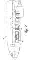
- FIGURE 2 is a diagrammatic side elevation of such an aircraft, illustrating the location of a lower lobe sleeping compartment in accordance with the present invention;
- FIGURE 3 is a diagrammatic top plan of the main cabin floor of the aircraft of FIGURE 2, in the area of a stairway access from the main cabin to the lower lobe sleeping compartment;
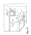
- FIGURE 4 is a diagrammatic section illustrating the area of the stairway between the main cabin and the lower lobe sleeping compartment;
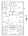
- FIGURE 5 is a floor plan of the lower lobe sleeping compartment of FIGURES 2-4;
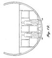
- FIGURE 6 is a diagrammatic section along
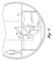
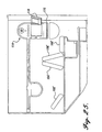
line 6--6 of FIGURE 5; - FIGURE 7 is a diagrammatic section along line 7--7 of FIGURE 5;
- FIGURE 8 is an enlarged fragmentary section of the aircraft frame in the area of the rear portion of the lower lobe sleeping compartment of FIGURES 2-7;
- FIGURE 9 is a diagrammatic side elevation of an aircraft illustrating an alternative embodiment of a lower lobe sleeping compartment in accordance with the present invention;
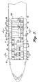
- FIGURE 10 is a diagrammatic top plan showing the floor plan of the lower lobe sleeping compartment of FIGURE 9;
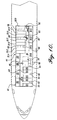
- FIGURE 11 is a diagrammatic top plan of an aircraft illustrating a lower lobe sleeping compartment and adjacent baggage/cargo area;
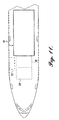
- FIGURE 12 is a top plan corresponding to FIGURE 11 showing a floor plan for the sleeping compartment;
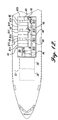
- FIGURE 13 is a diagrammatic top plan illustrating the floor plan of another lower lobe sleeping compartment with an adjacent baggage/cargo area;
- FIGURE 14 is a diagrammatic top plan corresponding to FIGURE 13 illustrating another floor plan for the lower lobe sleeping compartment adjacent to the baggage/cargo area;
- FIGURE 15 is a diagrammatic top plan illustrating another floor plan for a lower lobe sleeping compartment in accordance with the present invention;
- FIGURE 16 is a diagrammatic top plan illustrating yet another floor plan for a lower lobe sleeping compartment in accordance with the present invention;
- FIGURE 17 is a diagrammatic top plan illustrating still another floor plan for a lower lobe sleeping compartment in accordance with the present invention, in this case having dual longitudinally extending aisleways;
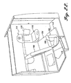
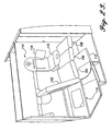
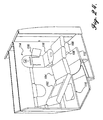
- FIGURE 18 is a diagrammatic top perspective of the lower lobe sleeping compartment of FIGURE 17;
- FIGURE 19 is a diagrammatic section along
line 19--19 of FIGURE 17; - FIGURE 20 is a diagrammatic top plan illustrating another embodiment of a lower lobe sleeping compartment in accordance with the present invention, including a cabin convertible between sitting, reclining, and sleeping configurations;
- FIGURE 21 is a diagrammatic side elevation of the cabin of FIGURE 20 illustrating a sitting configuration;
- FIGURE 22 is a top perspective of the cabin of FIGURE 21 illustrating the sitting configuration;
- FIGURE 23 is a top perspective corresponding to FIGURE 22 but with parts in different positions to illustrate a partially reclined configuration;
- FIGURE 24 is a top perspective corresponding to FIGURES 22 and 23 illustrating a more fully reclined configuration;
- FIGURE 25 is a diagrammatic side elevation illustrating an alternative embodiment of a cabin in a sitting configuration;
- FIGURE 26 is a top perspective of the cabin of FIGURE 25 illustrating the sitting configuration;
- FIGURE 27 is a top perspective corresponding to FIGURE 26 illustrating an almost fully reclined configuration;
- FIGURE 28 is a diagrammatic vertical section through the lower portion of an aircraft having another embodiment of a lower lobe sleeping compartment in accordance with the present invention;
- FIGURE 29 is a diagrammatic section along
line 29--29 of FIGURE 28; and - FIGURE 30 is a diagrammatic section along
line 30--30 of FIGURE 28. -
- FIGURE 1 shows a diagrammatic cross section of a representative aircraft of the type with which the lower lobe sleeping compartment in accordance with the present invention is intended to be used, in this case, a Boeing 777. For most of its length, the
aircraft 10 is of circular cross section, a semimonocoque design having an outer skin supported on an inner peripheral frame. Themain cabin floor 12 is disposed somewhat below the geometric center to provide alarge passenger compartment 14 having theusual seating 16, outboard overhead storage compartments 18 (primarily for carry-ons), inboard overhead storage compartments 20, and other amenities. Although FIGURE 1 shows a Boeing 777, the general layout is similar for a Boeing747,Boeing 767, Boeing MD11, Airbus A340/330, Ilyushin IL-86/96, as well as derivatives. - Still referring to FIGURE 1, of particular concern is the
lower lobe 22 below thebeams 24 for themain cabin floor 12. In the representative aircraft, the main cabin floor itself is of a thickness of about 1.5 to 2 inches and is supported on floor beams that are 5.5 to 7 inches deep. At the bottom of the aircraft, cargo floor beams 26 support a floor of a thickness of about 2 inches. As seen in FIGURE 1, the lower lobe will accommodate transverse rows of two standard LD-3cargo containers 28 side-by-side. Such cargo containers are about 79 inches wide by 60.4 inches long at the top, and 64 inches high at the center. The bottom outside corners are beveled to accommodate for the circular profile of the lower portion of the aircraft frame. Thus, the bottom of the LD-3 cargo container is about 61.5 inches wide, and the upper vertical portion of the outside wall of the cargo container is about 44.4 inches high, as compared to the 64-inch height at the center. The cargo containers are loaded through cargo doors in the side of the aircraft, and typically can be moved lengthwise along tracks. Other types of cargo containers or pallets can be loaded in thelower lobe 22. For example, the cargo area of the lower lobe typically will accommodate a pallet approximately 96 inches long by 125 inches wide and/or an LD-6 container which is approximately the same size and shape as two side-by-side LD-3 containers. In most aircraft currently in use, 96 inches is about the maximum width that will fit sideways through the cargo door, i.e., lengthwise of the aircraft. - With reference to FIGURE 2, in accordance with the present invention, a
sleeping compartment 30 is fitted in the lower lobe of theaircraft 10, below themain cabin floor 12. In order to retrofit or design into existing model aircraft or derivatives, it is desirable that as few changes as possible be required for the main floor of the cabin. Access to the lower lobe sleeping compartment for passengers can be by elevator and/or stairs. For example, FIGURE 3 is a plan view of themain passenger cabin 14 withseats 16 and permanent structures 34 (known as "monuments") such as lavatories, closets, and a galley area 34', and FIGURE 4 is a diagrammatic side elevation of the stairway area. In the illustrated embodiment of FIGURES 3 and 4, aU-shaped stairwell 32 is provided immediately in front of the galley area 34'. A U-shaped stairwell is preferred since only asingle floor beam 24 must be cut and impact on the main cabin layout is minimized. The U-shaped design also makes the stairwell appear roomier than a long, single, narrow stairwell because the wall orrailing 36 between the two sides of the stairwell can be angled for a more open feeling. The number of stairs from themain cabin floor 12 to thecentral landing 38 should preferably be approximately the same as the number of stairs from the landing to thefloor 39 of the lower lobe compartment. Another access consideration is the provision of an emergency exit hatch if it is not desired to provide a separate emergency exit in the lower lobe compartment. As seen in FIGURE 3, an openable emergency exit hatch 40 can be cut between adjacent floor beams 24 in the main cabin floor. - A lower lobe sleeping compartment of the size with which the present invention is concerned, i.e., a compartment that will accommodate a substantial number of passengers, will require at least one longitudinally extending aisle. The approximately 64-inch headroom permitted between the top of the cargo floor and the underside of the cabin floor beams is sufficient for a variety of beds and bunks, but is not convenient for an upscale comfortable sleeping compartment. Thus, it is desirable to make provision for more headroom, at least for parts of the sleeping compartment having one or more long aisleways. One way this can be achieved is by lowering the cargo floor. For example, FIGURE 5 shows a floor plan, described in more detail below, having a
front portion 42 and anaft portion 44. The dividing line between the two portions is immediately forward of any permanent structure including thestairway 32 and anadjacent lavatory 46. As seen in FIGURE 6, in the forward portion of the lower lobe compartment, thefloor 39f is substantially at the height of the cargo floor. With reference to FIGURE 7, in theaft portion 44 of the sleeping compartment, the central portion of the cargo floor is lowered primarily to provide increased headroom in theaisleway 48. As seen in FIGURE 8, the uppercargo floor beam 26 is cut a short distance inward from thestringer 50 for theskin 52. The stub of the original beam is connected to a lowerhorizontal floor beam 54. In this construction, the entire central portion of theaft compartment 44 is lowered. It has been found that headroom of 74 inches is much more appropriate and will accommodate 95% of full-grown males without stooping. Thus, the cargo floor can be lowered by 10 inches without undesirably affecting the layout of the lower lobe sleeping compartment due to the narrower space between the arcuate frame members at the floor level. For all embodiments described herein, the lowered floor portion may be provided only in the aisleways or throughout the lowered floor portion of the compartment. A less desirable alternative is to leave some or all of the cargo floor beams at the normal height, and lower the aisle floor between the beams such that passengers must step over the beams as they pass along the aisleway. Additional headroom also can be provided by "dishing" the ceiling structure over the aisleway for the finished compartment. This can help to increase the aesthetic appeal of the compartment without substantially affecting an efficient layout that will accommodate a maximum number of sleepers. See, for example, thebroken line 56 in FIGURE 7 representing a dished ceiling. - In the floor plan of FIGURE 5, one
long aisleway 48 extends lengthwise of the aircraft, aftward from thestairway 32, and offset toward the port side of the aircraft; whereas anotheraisleway 60 extends forward from thestairway 32, offset toward the starboard side of the aircraft. For a space-efficient arrangement of sleeping units, yet aesthetically pleasing and functional, all beds of this configuration are upper or lower bunks. The locations are designated B1-B20 in FIGURE 5, each including an upper bunk and a lower bunk, adding up to a total of forty bunks fitted in a space-efficient manner in the available lower hold space. The forward area includes locations B1-B8. Bunk units B6, B7, and B8 lie along the starboard wall of the aircraft with their lengths extending longitudinally. Each bunk can have a width of 28-34 inches and a length of about 80 inches. Convenient side entry is available for these beds. Access to the upper bunks can be by ladder, rope ladder, foot rests, or platform surfaces on top portions of the lower bunks, with suitable hand-holds and/or other mechanism for facilitating passenger entry to and egress from these beds. With reference to FIGURE 6, for each of units B6, B7, and B8, the lower bunk, such as B6L, can have a width at the bottom of about 30 inches, which is a typical desirable bed width. The upper bunk, such as bunk B6U, can have a wider mattress, such as 34 inches, and shifted outward due to the arcuate frame of the aircraft. Thus, thelongitudinal aisleway 60 can be wider at the top providing greater shoulder room and easier stooping due to the 64-inch headroom. The inward shifted lower bunk (bunk B6L, for example) can also provide a location for a shelf or step 62 to facilitate access to the outward-shifted upper bunk. In a similar manner the upper transverse bunk can be outward shifted and have a longer mattress than the lower transverse bunk B2L. - Returning to FIGURE 5, bunk units B1-B5 of the forward area 42 (nonlowered floor) are oriented transversely of the aircraft. With reference to FIGURE 6, the lower transversely extending bunk (such as bunk B2L the lower bunks of units B1, B3, B4, B5 will be the same) can be 82 inches long, for example, and shifted inward relative to the bunk immediately above it. The upper bunk can be a little longer at the bottom, and reserved for taller passengers. As seen in FIGURE 5, bunk units B2 and B3 and bunk units B4 and B5 can be positioned directly side-by-side with only a privacy wall between the adjacent beds. A short cross-aisle 64 provides side access to the bunks of units B3 and B4. Bunk unit B1 can be provided at the forward end of the compartment with a cross-aisle 64 between it and bunk unit B2. Another short cross-aisle 64 is provided aft of bunk unit B5. Thus, convenient side access is provided to each bunk of the
forward area 42. - Still referring to FIGURE 5, in the
aft area 44 of the sleeping compartment, the floor or aisles are lowered. Bunk units B9-B20 are located in this area. Bunk unit B9 extends longitudinally along the starboard side of the aircraft at the foot of the stairway and is substantially identical to bunk unit B8 and located directly behind it. The orientation of the other aft bunks is shown in FIGURE 7, which illustrates a section through bunk units B1 and B16, but the section would be the same if the section line is shifted forward or aftward in therear section 44 of the sleeping compartment through any of bunk units B14-B20. Other than the lowered floor providing for 74-inch headroom in theaisle 48, the layout is the mirror image of the layout for the forward bunk area, and the bunk sizes are the same. Bunk units B10, B11, B12, and B 13 extend longitudinally along the port side of the aircraft, with the lower bunk, such as bunk B11L, shifted inward and narrower than the associated upper bunk, such as bunk B11U. With reference to FIGURE 5, bunk units B 14 and B15 are grouped together, as are bunk units B17 and B18, and bunk units B 18 and B19. Bunk unit B20 is provided at the aft end of the compartment, in line with the aft end of the longitudinally extending bunk unit B 13. Short cross-aisles 66 provide side access to each bunk. Closets and/orstorage compartments 68 can be provided at the ends of the cross-aisles 66 and at the ends of theforward cross-aisles 64. - FIGURE 9 and FIGURE 10 show essentially the same configuration as FIGURES 2 and 4-7 but with an
elevator 70 for access between the main cabin and the lower lobe sleeping compartment in accordance with the present invention. Bunk units B1-B20 are located and sized substantially identically for this embodiment as for the previously described embodiment. - Although it has been found that aisleways with increased headroom are highly desirable, nevertheless it is envisioned that the sleeping compartments can be less than permanent additions to the aircraft. For locations where the cargo floor is altered, much more time will be required to restore the aircraft to a cargo-carrying capability than for areas where the cargo floor and its loading components are unaltered. Thus, at least part of the lower lobe sleeping compartment can be provided with aisleways of about 64-inch headroom (or whatever the standard lower lobe height is in the particular aircraft) with, perhaps, fewer beds and/or aisles that are not as long as in the lowered floor area. For maximum flexibility, the nonlowered floor sleeping compartment area should be located adjacent to an existing cargo door and, as discussed in more detail below, the sleeping compartment for that area can be provided in modules loadable through the cargo door, secured in place on the cargo floor or on cargo roller trays, and connected together. Thus, the nonlowered floor area can be quickly and easily changed to cargo-carrying capability without necessarily altering the more spacious lowered floor area of the sleeping compartment. Also, it is envisioned that the lower lobe sleeping compartment would probably be provided for first class and/or business class passengers who typically ride toward the front of the aircraft, such that the forward lower lobe would preferably be used for the sleeping compartment. This conveniently lends itself to positioning the nonlowered floor part of the sleeping compartment adjacent to the forward cargo door, with the more permanent amenities (lavatory and stairwell/elevator, for example) positioned slightly to the rear, and the lowered floor component aft of the stairwell.
- For example, with reference to FIGURE 11, the
aft portion 44 of either of the lower lobe sleeping compartments previously described can be closed at its forward end, just ahead of thelavatory 46 shown in FIGURE 5 and in FIGURE 10.Standardized cargo containers 28 such as cargo pallets or Unit Load Devices (ULDs) then can be loaded through thestandard cargo door 72, in the conventional manner, the only difference being that the aft portion of the aircraft lower lobe in this location is dedicated to thesleeping compartment 44. The layout of thesleeping compartment 44 can be as shown in FIGURE 12, which corresponds generally to the layouts previously described for bunk units B9-B20, adjacent to themain cabin access 70 or 32 (elevator/stairwell), and with aforward lavatory 46. Conversion can be by removal of the forward wall 74, followed by insertion and assembly of sleeping compartment modules to form the forward area 42 (see FIGURE 5 and FIGURE 10) which rests on the cargo hold floor or roller trays. One such module can encompass bunk units B1, B2, and B6, a second module can encompass bunk modules B3, B4, and B7; and a third module can encompass the remaining area of theforward compartment 42 including bunk units B5 and B8. These modules can be loaded individually through thecargo door 72 and assembled within the aircraft if it desired to convert from the cargo carrying capability to a larger lower lobe sleeping compartment. The aft portion also could be configured for cargo carrying, but much more work would be required to raise the floor and incorporate standard cargo handling equipment in addition to removing the sleeping modules. In an infrequent conversion, the elevator/stairwell and lower lavatory also could be removed. - The modified design shown in FIGURE 13 illustrates how the lower lobe compartment can be utilized as sleep and rest areas for passengers, flight attendants, and pilots. The sleeping compartment corresponds to the aft portion 44 (see FIGURE 11) which includes a lowered floor, at least in the aisleways, and a front wall 74 separating the compartment from the forward part of the lower lobe reserved for cargo, such as
standardized cargo containers 28. The forward wall is positioned at the same location as for the previously described embodiment, namely, in front of a sharedlavatory 46. Another permanent monument is thestairway 32 located immediately aft of the lavatory. Passenger sleeping is provided in bunk units B1-B7. Bunk units B1, B2, and B3 extend along the starboard wall of the aircraft and are identical to bunk units B6, B7, and B8 of the embodiment of FIGURE 5. Bunk unit B4 is spaced inward of bunk units B2 and B3, along the central vertical plane of the aircraft, with anaisleway 76 between unit B4 and the starboard side units. Unit B4 has upper and lower bunks, both of which may be accessed from the side by way ofaisleway 76. The last three passenger bunk units are labeled B5, B6, and B7 in FIGURE 13, corresponding to any of the transversely extending units of FIGURE 5, except that in the case of the configuration of FIGURE 13, the upper and lower bunks of units B5, B6, and B7 have end access fromaisleway 76 only. A storage unit S1 can be provided acrossaisleway 76 from the passenger bunk units B5, B6, and B7. - The attendant rest area can be provided at the aft of the lower lobe sleeping compartment, separated from the remainder of the compartment by a door or
curtain 78. This areas consists of bunk units B8, B9, and B10, each including an upper bunk and a lower bunk, such units being arranged in a U-configuration. - Toward the other end of the sleeping compartment, a high-comfort attendant/
pilot seat 80 can be provided, immediately in front of bunk unit B4. By slipping in front of the seat, access is provided to apilot cabin 82 with relatively increased space for resting and sleeping including single-bed units B11 and B12 (no upper bunks) and storage or restinglocations - The configuration of FIGURE 14 has many characteristics similar to the configuration of FIGURE 13. Passenger bunk units B1, B2, and B3 are identical to the similarly numbered units of the preceding figure. A center, high-comfort attendant/
pilot rest seat 80 is provided at the same location as for FIGURE 13. Transversely extending passenger bunk units B4 and B5 are provided substantially immediately aft ofseat 80, each having end access to upper and lower passenger bunks. An additional longitudinally extending passenger bunk unit B6 extends along the port side of the aircraft, in front of the transversely extending units B4 and B5. A single pilot bunk andrest area 88 is provided aft of bunk unit B5, with aseparate entrance door 90, recliner or high-comfort seat 92, andsingle bed 94. Another door orcurtain 93 in theaisleway 76, aft of thedoor 90 to the pilot cabin, leads to an attendant rest area having bunk units B7, B8, B9, and B10 arranged in a generally rectangular configuration with anopen area 97 between them. Storage units S1 and S2 can be provided between bunk units B3 and B7, one at each side of the entrance door orcurtain 93 that segregates the attendant rest area from the remainder of thelower lobe compartment 44. - FIGURE 15 and FIGURE 16 each show high-density lower lobe sleeping compartments using both the forward
nonlowered floor area 42 and aft loweredfloor area 44. In the configuration of FIGURE 15, thestairway 32 andlavatory 46 are located as in the previously described embodiments. The forwardmodular portion 42 with the nonlowered floor can include closely packed transversely extending bunk units B1-B6, all having end access except the aft unit B6 which has side access from its aft side by way of a cross-aisle 64. Similarly, in the aft portion of the compartment, transversely extending bunk units B7-B 15 are provided, with no cross-aisles, so that these units have end access, except the front unit B7. The bottom bunks are shifted inward in the manner shown in FIGURES 6 and 7 due to the curvature of the aircraft frame. Along the starboard side, cabin units C1-C6 can be provided, each having a single bed or, for example, a convertible recliner of the type discussed in more detail below. These units, being larger than the others and having the convenient side access, could command a premium fare. Another similar cabin C7 can be located on the port side of the aircraft adjacent to thestairway 32. - In the configuration of FIGURE 16, transversely extending, high-density bunk units B1-B6 are provided at the forward, port side of the sleeping compartment, in the
nonlowered floor area 42 which can be more easily convertible to cargo/baggage space as described above. These units are identical to units B1-B6 of the configuration of FIGURE 15. Bunk units B7-B11 are provided at the same locations as for the similarly numbered units shown in FIGURE 15, unit B11 being the aftmost unit with across aisle 66 behind it so that this unit has side access. Additional bunk units B12-B17 can be located at the starboard side of the aircraft, extending longitudinally, one behind the other. Each unit B12-B17 has side access and includes a lower bunk offset inward relative to an upper bunk, as previously described. At the rear of the compartment, cabins C1-C4 can be provided, each having a door opening into the cross-aisle 66 which extends from one side of the compartment to the other. Each cabin can include a single bed, recliner, or other upscale amenities for use by pilots or commanding a premium fare when used by passengers. A final cabin C5 can be provided behind thestairway 32 as in the embodiment of FIGURE 15, accessible by a short cross-aisle 66 behind thestairway 32. - FIGURES 17-19 illustrate another configuration for a lower lobe sleeping compartment, in this case using two longitudinally extending
aisleways 100 so that all bunks can be arranged longitudinally. The configuration includesbunk units B 1 and B2 centrally located in front of thelavatory 46 and bunk units B3, B4, and B5 located behind the stairway. In each case, the upper bunk of the unit has one side access opening toward one of theaisles 100, whereas the lower bunk of the same unit has a side access opening toward the other of the aisles. This helps to prevent congestion. At the starboard side of the aircraft, bunk units B6-B 12 are provided, of the type generally described for bunk units extending longitudinally at one side or the other, including the lower bunk shifted inward relative to the upper bunk. Bunk units B13-B19 at the opposite side are the mirror image of bunk units B6-B12. At one or the other end, two short bunk units B20 and B21 can be provided, with smaller side access openings toward theaisleways 100. The floor can be lowered in the manner described previously, or, as illustrated in FIGURE 19, only for the long aisleways, preferably only in theaft portion 44 of the sleeping compartment so that theforward portion 42 can be more quickly and easily converted to baggage/cargo carrying by use of standardized equipment. Thus, the bunk units of the forward unit preferably are modular, and loadable through theconventional cargo door 72 for being secured together with the lesser headroom in the forward portions ofaisleways 100. It should be noted that in FIGURE 18, the starboard wall (closest to the viewer) is deleted for the long row of side bunks B6-B12 and for the center bunks B1-B5, for ease of illustration. - The configuration of FIGURE 20 has characteristics in common with the previously described configurations. Toward the front, an attendant rest area is provided of bunk units B1, B2, B3, and B4 arranged in a generally rectangular configuration, similar to the aft attendant rest area shown in FIGURE 14 (numbered B7-B10 in that figure). A storage unit S1 can be provided immediately behind
bunk unit B 1 which extends longitudinally of the aircraft at the starboard side. A door orcurtain 95 separates the attendant area from the remainder of the lower lobe sleeping compartment. A pilot's cabin C1 is provided immediately to the rear of bunk unit B4, including, for example, arecliner 92. To the aft of the attendant rest area, bunk units B5-B10 extend longitudinally of the aircraft at the starboard side, one behind the other, each having a lower bunk shifted inward relative to an upper bunk. In theaft portion 44 of the sleeping compartment, and at the port side, transversely extending bunk units B11-B16 are provided, unit B11 being a single unit with a cross-aisle 66 between it andunit B 12, units B 12 and B 13 being placed side-by-side with only a privacy wall between them, units B13 and B14 being spaced apart by a cross-aisle 66, units B14 and B15 being placed side-by-side with a privacy wall between them, and a cross-aisle 66 between units B15 and B16. This allows for side access to all of bunks B5-B16. An attendant/pilot rest chair 80 is provided in the location described with respect to other embodiments, close to thestairway 32, with an additional bunk unit B 17 extending longitudinally along the port side of the aircraft adjacent to the stairwell, in front of the transversely extending bunk unit B11. Thus, in the configuration of FIGURE 20, if other arrangements are made in or around the main cabin for pilot and attendant rest areas, the nonloweredforward portion 42 can be disassembled so that this area can be used for cargo/baggage carrying, or other modular passenger units can be installed. Bunk units B6-B17 will remain for passenger use in either case. - FIGURES 21-24 illustrate diagrammatically a representative recliner that may be provided in a lower lobe cabin. FIGURES 21 and 22 show the basic components of the recliner, namely,
pads base structure 110. FIGURES 21 and 22 show the recliner in a sitting configuration, with anextended footrest 112 in front of a lowervertical pad 106. Anend pad 108 is folded behindpad 106 and, at the opposite side ofpad 106,horizontal pad 104 acts as the seat. Theupper end pad 102 is supported in position for a backrest. As best seen in FIGURE 22, the cabin can include aside module 114 having a tray ortable component 116 andvideo display 118, both of which can be folded back into the module. Standard aircraft amenities can be provided within the module, including ventilation, reading lights, call buttons, and visual and audible alarms, for example. From the condition shown in FIGURE 22, the recliner can be reconfigured to the conditions shown in FIGURES 23 and 24, FIGURE 23 showing a raised legrest of alignedpads backrest 102 reclined. From this position, the backrest can be reclined fully onto its supporting base so that the pads 102-108 extend substantially horizontally for sleeping. Tray or table 116 andvideo display 118 can be retracted into the module so as not to interfere with the occupant adjusting his or her legs, or for entry into or egress from the cabin. - FIGURES 25-27 show another arrangement of pads 102'-108' which can be configured in a sitting position (FIGURES 25 and 26) or fully or partially reclined position (see FIGURE 27).
Module 114 including tray or table 116 andvideo display 118 are identical to that described with reference to FIGURES 22-25. - In the configuration shown in FIGURE 28 through FIGURE 30, side-by-side
lower bunks main aisle 124.Bunks 120 are immediately adjacent to theaisle 124 so that side access may be had to these bunks. Theouter bunks 122 have end access atcross aisles 126 provided for this purpose.Upper bunks 128 extend transversely of the aircraft, over the bottom bunks. Oppositely disposed transverse bunks can be used on aircraft having lower lobes configured to accommodate side-by-side LD-1 containers, such as a Boeing 747 or its derivatives. Depending on the available width, units having transversely extending upper bunks may be possible only at one side of the aircraft. With reference to FIGURE 29, the upper bunks can each be about 30.5 inches wide by about 79.5 inches long, withprivacy walls 130 at the sides and between upper bunks. With reference to FIGURE 28, both the upper and lower bunks can have a height of about 25 inches. With reference to FIGURE 30, each lower bunk can be about 80 inches long, such that two bunks fit lengthwise beneath a module having five upper bunks. The inboardlower bunks 120 can be about 29 inches wide, whereas the outboardlower bunks 122 can be about 25 inches wide at the bottom and bevel outward to a maximum width of about 38 inches at the top. Another possibility is to provide one or more double-wide bunks at the bottom or at the top. It still is desirable to provide the lowered aisle at the center for increased head room. In a typical embodiment, the aisle will be about 21 inches wide and have head room of about 75 inches. - In all cases, for lower lobe compartments have standard cargo floors (not lowered) conversion time between sleeping compartment and cargo carrying capability can be as short as two or three hours if umbilical type connections and modular containers are used. It is envisioned that the conversion process will take much longer in the lowered floor areas, possibly four to five days.
- Individual bunks/sleeping units can be provided with general illumination lights, reading lights, audio and/or audiovisual entertainment, heavy curtains (highly opaque and noise absorbing), small storage spaces for books, shoes and personal items, separate oxygen canisters/masks, smoke detectors, return-to-seat lights, PA speakers, and lapbelt restraints and/or airbags, so that the bunks could continue to be used even during turbulence. Provision can be made for orientation of the aircraft during flight. For example, the aircraft may cruise at a nose-up angle of up to 2.5°. Beds can be angled to accommodate, and/or tapered mattresses can be provided. At least one dressing area should be included, which may be incorporated into the oversize lavatory.
- While the preferred embodiment of the invention has been illustrated and described, it will be appreciated that various changes can be made therein without departing from the scope of the invention.
Claims (14)
- A passenger transport aircraft having a fuselage including a main passenger cabin (14) for accommodating seated passengers and a lower lobe compartment (22) beneath the main passenger cabin for normally carrying cargo, a sleeping compartment (30) located in the lower lobe compartment (22) and accessible from the main cabin (14), the sleeping compartment (30) including a forward area (42) and an aft area (44), the aircraft having a cargo door (72) for access to the lower lobe adjacent to one of the forward and aft sleeping compartment areas (42,44) with the other of the forward and aft sleeping compartment areas being remote from such cargo door (72), the sleeping compartment (30) being convertible between a first configuration in which each of the forward and aft sleeping compartment areas (42,44) has several beds (B) and an aisle (48,60) extending substantially longitudinally of the aircraft and a second configuration in which one of the sleeping compartment are as (42) is modified for accommodating cargo while the other sleeping compartment area (44) has several beds (B) and an aisle (48) extending substantially longitudinally of the aircraft characterized in that the sleeping compartment area (42) adjacent to the cargo door (72) has an unaltered cargo floor (60) for receiving standardized cargo carriers (28) in the second configuration, the sleeping compartment area (44) remote from the cargo door (72) having a floor portion in the area of the aisle (48) lowered relative to the unaltered cargo floor (60) of the sleeping compartment area (42) adjacent to the cargo door (72).
- Aircraft as claimed in claim 1, wherein the ceiling structure (56) between said passenger cabin (14) and said lower lobe (22) is dished so as to provide additional headroom.
- Aircraft according to one of the preceding claims, in which the forward sleeping compartment area (42) includes a longitudinally extending aisle (60) offset toward one side of the aircraft and the aft sleeping compartment area (44) includes a longitudinally extending aisleway (48) offset toward the other side of the aircraft.
- Aircraft according to one of the preceding claims, in which in the second configuration the sleeping compartment area (44) remote from the cargo door (72) has a front wall (74), the front wall being removable during conversion from the second configuration to the first configuration for providing access between the forward and aft sleeping compartment areas (42,44).
- Aircraft according to any of the preceding claims, wherein the sleeping compartment (30) includes modules for loading through the cargo door (72) and for securing together to form at least a portion of the sleeping compartment.
- Aircraft according to one of the preceding claims, in which the transversely oriented stacked bunks (B1-B5) are provided in units having two upper bunks and two lower bunks located side-by-side, and including transversely extending cross-aisles (64) for side access to the transversely oriented bunks.
- Aircraft according to one of the preceding claims, including storage compartments (68) at the ends of the cross-aisles (64), remote from the longitudinally extending aisle (48).
- Aircraft according to one of the preceding claims, including a U-shaped stairway (32) for access between the main cabin (14) and the lower lobe sleeping compartment (22), the stairway having a landing area (38) located approximately midway between the top and bottom of the stairway.
- Aircraft according to one of the preceding claims, in which the sleeping compartment (30) includes a pilot/attendant area (B1-B4,C1) segregated from a passenger area (B6-B17).
- Aircraft according to one of the preceding claims, in which the sleeping compartment (30) includes a plurality of bunk units (B) and at least one cabin (46) having amenities different from the amenities provided for the bunk units.
- Aircraft according to one of the preceding claims, in which the sleeping compartment (30) includes a longitudinal aisle extending substantially the full length of the sleeping compartment, a row of sleeping units (C1-C6) disposed longitudinally along one side of the aisleway, and a plurality of sleeping units (B1-B15) disposed transversely of the aircraft at the other side of the aisleway.
- Aircraft according to any of the preceding claims, the sleeping compartment (30) having a first longitudinally extending aisle (100) and a second longitudinally extending aisle (100) offset transversely from the first aisle, and three rows of longitudinally extending sleeping units (B1-B19) separated by the aisles.
- The aircraft defined in claim 12, in which the sleeping units (B1-B19) include at least one bunk unit having an upper bunk with side access to the first aisle but not the second aisle and a lower bunk having side access to the second aisle but not the first aisle.
- The aircraft as defined in any of the preceding claims, wherein the sleeping compartment (30) a plurality of longitudinally oriented lower bunks (120,122) on both sides of the aisle (124), and a plurality of transversely oriented upper bunks (128) above the lower bunks on both sides of the aisle.
Priority Applications (1)
| Application Number | Priority Date | Filing Date | Title |
|---|---|---|---|
| DE69829445T DE69829445T3 (en) | 1997-09-10 | 1998-09-10 | Sleeper cabins in the underfloor area of an airplane |
Applications Claiming Priority (4)
| Application Number | Priority Date | Filing Date | Title |
|---|---|---|---|
| US5833197P | 1997-09-10 | 1997-09-10 | |
| US58331P | 1997-09-10 | ||
| US09/144,405 US6152400A (en) | 1997-09-10 | 1998-08-31 | Aircraft lower lobe sleeping compartment |
| US144405P | 1999-07-16 |
Publications (4)
| Publication Number | Publication Date |
|---|---|
| EP0901963A2 EP0901963A2 (en) | 1999-03-17 |
| EP0901963A3 EP0901963A3 (en) | 1999-10-20 |
| EP0901963B1 true EP0901963B1 (en) | 2005-03-23 |
| EP0901963B2 EP0901963B2 (en) | 2011-08-31 |
Family
ID=26737507
Family Applications (1)
| Application Number | Title | Priority Date | Filing Date |
|---|---|---|---|
| EP98203035A Expired - Lifetime EP0901963B2 (en) | 1997-09-10 | 1998-09-10 | Aircraft lower lobe sleeping compartment |
Country Status (3)
| Country | Link |
|---|---|
| US (1) | US6152400A (en) |
| EP (1) | EP0901963B2 (en) |
| DE (1) | DE69829445T3 (en) |
Cited By (1)
| Publication number | Priority date | Publication date | Assignee | Title |
|---|---|---|---|---|
| EP3850541A4 (en) * | 2018-09-10 | 2022-08-17 | Rockwell Collins, Inc. | Passenger rest compartments for remote aircraft spaces |
Families Citing this family (80)
| Publication number | Priority date | Publication date | Assignee | Title |
|---|---|---|---|---|
| DE69923925T2 (en) * | 1998-12-14 | 2006-02-23 | The Boeing Co., Seattle | Accommodation units in the upper area of the aircraft cabin |
| DE19926782B4 (en) * | 1999-06-11 | 2004-07-15 | Airbus Deutschland Gmbh | Service unit for passenger cabins, in particular for aircraft passenger cabins |
| DE19926776B4 (en) * | 1999-06-11 | 2004-07-22 | Airbus Deutschland Gmbh | Functional unit for passenger cabins, in particular for aircraft passenger cabins |
| WO2009079668A2 (en) * | 2007-12-17 | 2009-06-25 | Rajasingham Arjuna Indraeswara | Vehicle occupant support |
| DE10017500B4 (en) * | 2000-04-07 | 2004-07-08 | Airbus Deutschland Gmbh | Fire extinguishing system for a passenger plane |
| ATE309110T1 (en) | 2001-08-09 | 2005-11-15 | Virgin Atlantic Airways Ltd | A SEATING ARRANGEMENT AND A PASSENGER ACCOMMODATION UNIT FOR A VEHICLE |
| US6659225B2 (en) | 2001-09-13 | 2003-12-09 | The Boeing Company | Stairway for enabling access to an overhead area within a fuselage of an aircraft |
| FR2842498B1 (en) * | 2002-07-19 | 2005-05-13 | Airbus | AIRCRAFT CABIN MODULE |
| FR2842497B1 (en) * | 2002-07-19 | 2004-10-01 | Airbus | AIRCRAFT CABIN MODULE FOR PASSENGERS |
| US6772977B2 (en) * | 2002-10-10 | 2004-08-10 | The Boeing Company | Aircraft with multipurpose lower decks and associated methods of manufacture |
| EP1407963B2 (en) * | 2002-10-10 | 2010-08-25 | The Boeing Company | Integrated high-speed aircraft and associated methods of manufacture |
| DE10339077A1 (en) * | 2003-08-26 | 2005-03-31 | Airbus Deutschland Gmbh | Passenger compartment in the cabin of a commercial airplane |
| AU2005214298B2 (en) * | 2004-02-20 | 2009-12-17 | Singapore Airlines Limited | An aircraft cabin |
| US6986485B2 (en) * | 2004-03-22 | 2006-01-17 | The Boeing Company | Overhead space access stowable staircase |
| US7080806B2 (en) * | 2004-03-26 | 2006-07-25 | The Boeing Company | Overhead space access conversion monument and service area staircase and stowage system |
| US20060249624A1 (en) * | 2004-06-24 | 2006-11-09 | Wagner William J | System and method for converting a passenger aircraft to a cargo aircraft |
| DE102004033068B4 (en) * | 2004-07-08 | 2008-09-25 | Airbus Deutschland Gmbh | Airliner with a main deck and a lower deck |
| FR2886622B1 (en) * | 2005-06-02 | 2007-07-20 | Airbus France Sas | PLANE LONG-MAIL |
| US20070102581A1 (en) * | 2005-06-22 | 2007-05-10 | Wagner William J | System and method for converting a passenger aircraft to a cargo aircraft |
| US7562844B2 (en) * | 2005-07-18 | 2009-07-21 | The Boeing Company | Multiple attendant galley |
| DE102005060369A1 (en) * | 2005-12-16 | 2007-07-05 | Airbus Deutschland Gmbh | Aircraft for civil aviation, has module carrier accommodating several module elements such that each module element includes integrated system element |
| DE102006003585B4 (en) * | 2006-01-25 | 2015-07-02 | Airbus Operations Gmbh | Restedeck in an airplane with herringbone arranged resting cabins |
| US20090206201A1 (en) * | 2006-04-27 | 2009-08-20 | Johnson Richard J | Airplane with collapsible crew rest compartment modules |
| DE102006031361B4 (en) * | 2006-07-06 | 2011-03-10 | Airbus Operations Gmbh | Aircraft with a reclining device installed therein for the emergency medical care of patients |
| US20080011898A1 (en) * | 2006-07-12 | 2008-01-17 | Richard Wilton White | Flying saucer |
| FR2903663B1 (en) * | 2006-07-12 | 2009-06-12 | Airbus France Sas | REST ASSEMBLY FOR AN AIRCRAFT. |
| US20080034678A1 (en) * | 2006-08-08 | 2008-02-14 | Emma Flexen | Airplane simulator playhouse |
| DE102007009280A1 (en) * | 2007-02-26 | 2008-08-28 | Airbus Deutschland Gmbh | Crew member checking module for aircraft, has base area with module-luggage rack-case of aircraft integrated in module, where module-luggage rack-case is accessible from interior of module |
| DE102007009279A1 (en) * | 2007-02-26 | 2008-08-28 | Airbus Deutschland Gmbh | Module for airplane for locating crew members, is carried out to mount within floor zone of passenger cabin of airplane, where module has bottom area that has luggage compartment storage space of airplane |
| EP2125514B1 (en) | 2007-02-26 | 2013-12-11 | Airbus Operations GmbH | Module for accommodation of crew members having a stowage bin usable from inside the module |
| DE102007009863B4 (en) | 2007-02-28 | 2016-02-18 | Airbus Operations Gmbh | Combined module for an airplane |
| DE102007015520A1 (en) * | 2007-03-30 | 2008-10-02 | Airbus Deutschland Gmbh | Underbody system for an aircraft |
| GB0708891D0 (en) * | 2007-05-09 | 2007-06-20 | Airbus Uk Ltd | Aircraft toilet facility |
| FR2917372B1 (en) * | 2007-06-15 | 2009-12-18 | Airbus France | HOLDING DEVICE INTENDED IN PARTICULAR FOR BAGGAGE IN AN AIRCRAFT BODY |
| FR2917377B1 (en) * | 2007-06-15 | 2009-08-07 | Airbus France Sas | DEVICE FOR ARRANGING AN AIRCRAFT FOR THE REST OF CREW MEMBERS AND AN AIRCRAFT COMPRISING IT |
| US8720820B2 (en) * | 2007-06-25 | 2014-05-13 | The Boeing Company | Aircraft having multiple seating configurations and associated systems and methods |
| EP2062816A1 (en) * | 2007-11-20 | 2009-05-27 | Airbus Deutschland GmbH | Rest module with a first partial module with direct access to a possible second partial module |
| US9452817B1 (en) | 2010-03-03 | 2016-09-27 | The Boeing Company | Aircraft having split level cabin floors |
| US9108719B2 (en) | 2010-03-03 | 2015-08-18 | The Boeing Company | Aircraft with AFT split-level multi-deck fusealge |
| US10589836B2 (en) | 2010-03-03 | 2020-03-17 | The Boeing Company | Split level forward double deck airliner |
| US8336939B2 (en) | 2010-10-04 | 2012-12-25 | Air Methods Corporation | Roll-on, foldable litter and patient handling system for emergency transport vehicles |
| CA3048866C (en) | 2010-10-15 | 2021-07-27 | Bombardier Inc. | Aircraft interior configuration |
| DE102011013049A1 (en) * | 2011-03-04 | 2012-09-06 | Airbus Operations Gmbh | aircraft area |
| DE102011107533A1 (en) * | 2011-07-14 | 2013-01-17 | Airbus Operations Gmbh | Door for a stay module, stay module and aircraft |
| WO2013052784A1 (en) | 2011-10-07 | 2013-04-11 | Bombardier Inc. | Aircraft divan convertible to a bunk bed |
| WO2013067021A1 (en) * | 2011-11-01 | 2013-05-10 | C&D Zodiac, Inc. | High privacy passenger aircraft cabin arrangement |
| EP2825422A4 (en) * | 2012-01-31 | 2016-10-19 | Rajasingham Arjuna Indraeswaran | Vehicle occupant support |
| JP6102910B2 (en) * | 2012-02-23 | 2017-03-29 | 横浜ゴム株式会社 | Installation method of aircraft restroom unit and aircraft |
| EP2818411B1 (en) * | 2012-02-23 | 2018-09-26 | The Yokohama Rubber Company, Limited | Airplane lavatory unit and disposition configuration therefor |
| EP2844557B1 (en) | 2012-05-04 | 2019-07-10 | Bombardier Inc. | Seating arrangement convertible to a bunk bed |
| US9908623B2 (en) * | 2013-05-10 | 2018-03-06 | B/E Aerospace, Inc. | Wall mounted stowage compartment |
| DE102013008288A1 (en) * | 2013-05-15 | 2014-11-20 | Airbus Operations Gmbh | aircraft area |
| EP3068665B1 (en) * | 2013-11-12 | 2020-12-30 | B/E Aerospace, Inc. | Aircraft seat with taxi, takeoff and landing lie flat position capability |
| DE102014102378A1 (en) * | 2014-02-24 | 2015-08-27 | Airbus Operations Gmbh | Module for an aircraft cabin with a seat attached to a door |
| DE102014205106A1 (en) * | 2014-03-19 | 2015-09-24 | Airbus Operations Gmbh | Sleeping box, sleeping box arrangement and aircraft area |
| JP2017516716A (en) * | 2014-05-30 | 2017-06-22 | ゾディアック エアロスペース | Lower deck commercial room |
| US10891504B2 (en) * | 2014-06-13 | 2021-01-12 | Rockwell Collins, Inc. | Passenger rest compartments for remote aircraft spaces |
| US10909397B2 (en) * | 2014-06-13 | 2021-02-02 | B/E Aerospace, Inc. | Aircraft suite including main cabin compartment and lower lobe rest compartment |
| EP3075650A1 (en) * | 2015-03-30 | 2016-10-05 | Airbus Operations GmbH | Large self-carrying monument assembly for an aircraft and an aircraft having such a monument assembly |
| WO2016164293A2 (en) * | 2015-04-08 | 2016-10-13 | Zodiac Seat Shells U.S. Llc | Passenger accommodation systems including partition walls |
| DE102015206435A1 (en) * | 2015-04-10 | 2016-10-13 | Airbus Operations Gmbh | Passenger cabin area |
| EP3170747A1 (en) * | 2015-11-18 | 2017-05-24 | Airbus Operations GmbH | Aircraft for the transport of passengers having lower deck facilities |
| CN105857616A (en) * | 2016-03-31 | 2016-08-17 | 陈刚 | Airliner flat-on economy cabin |
| FR3050434B1 (en) * | 2016-04-26 | 2019-06-28 | Airbus Operations | SIDE CABINET FOR AIRCRAFT COCKPIT WITH ARTICULATED MONOBLOCK PARTS |
| FR3055128A1 (en) * | 2016-08-17 | 2018-02-23 | Zodiac Seats France | ARRANGEMENT OF SEATS FOR INCREASING THE INTIMACY OF PASSENGERS, IN PARTICULAR AN AIRCRAFT |
| CN110914154A (en) * | 2016-08-24 | 2020-03-24 | 赛峰公司 | Enhanced lower deck commercial cabin |
| US10377494B2 (en) | 2017-01-12 | 2019-08-13 | C&D Zodiac, Inc. | Aircraft divider assembly |
| DE102017106411B4 (en) * | 2017-03-24 | 2022-05-12 | Airbus Operations Gmbh | Multifunctional container system for producing a container that can be used in an aircraft hold |
| FR3065104B1 (en) * | 2017-04-07 | 2023-01-20 | Zodiac Aerospace | REMOTE MONITORING SYSTEM FOR A ZONE INTENDED TO ACCOMMODATE AT LEAST ONE PASSENGER OF AN AIRPLANE AND AIRCRAFT CAB EQUIPPED WITH SUCH A REMOTE MONITORING SYSTEM. |
| FR3066475A1 (en) * | 2017-05-19 | 2018-11-23 | Zodiac Aerospace | AIRCRAFT CABIN COMPRISING A CARGO AREA INTENDED TO HOST PASSENGERS |
| FR3069847B1 (en) * | 2017-08-02 | 2020-09-11 | Airbus Interiors Services | AIRCRAFT WITH A SPECIAL ARRANGEMENT MODULE |
| DE102017221278A1 (en) * | 2017-11-28 | 2019-05-29 | Airbus Operations Gmbh | System for the automatic unlocking of a door of an aircraft |
| WO2019207211A1 (en) | 2018-04-25 | 2019-10-31 | Societe Air France | Sleeper compartments for passengers |
| US11235852B2 (en) | 2018-09-10 | 2022-02-01 | B/E Aerospace, Inc. | Bidirectional hatch for passenger rest compartment |
| US11447250B2 (en) | 2018-09-10 | 2022-09-20 | Rockwell Collins, Inc. | Optimized configuration for lower lobe passenger rest cabins |
| US11167850B2 (en) | 2018-09-10 | 2021-11-09 | Rockwell Collins, Inc. | Passenger friendly overhead rest cabin configuration |
| WO2020112203A1 (en) * | 2018-09-10 | 2020-06-04 | Rockwell Collins, Inc. | Passenger rest compartments for remote aircraft spaces |
| US11584531B2 (en) | 2019-05-21 | 2023-02-21 | Bombardier Inc. | Aircraft with crew quarters |
| US11952120B2 (en) | 2020-02-20 | 2024-04-09 | Air New Zealand Limited | Multi-layer sleeping compartment |
| JP1684497S (en) | 2020-02-20 | 2021-05-10 |
Family Cites Families (36)
| Publication number | Priority date | Publication date | Assignee | Title |
|---|---|---|---|---|
| GB596257A (en) * | 1945-07-25 | 1947-12-31 | George Edward Lengerke | Improvements in aeroplanes |
| US2092655A (en) * | 1934-06-09 | 1937-09-07 | Curtiss Wright Corp | Airplane with sleeping accommodations |
| US2280065A (en) * | 1937-04-10 | 1942-04-21 | Roode Trimble De | Vehicle |
| US2124003A (en) * | 1937-09-22 | 1938-07-19 | Glenn L Martin Co | Aircraft construction |
| US2310573A (en) * | 1939-09-09 | 1943-02-09 | Douglas Aircraft Co Inc | Aircraft cabin |
| FR1002271A (en) * | 1946-08-29 | 1952-03-04 | Improvements made to the means for transporting travelers, in particular sleeping travelers | |
| US3898704A (en) * | 1974-07-18 | 1975-08-12 | Mc Donnell Douglas Corp | Convertible seat-bed equipment |
| US4022404A (en) * | 1975-10-22 | 1977-05-10 | The Boeing Company | Upper deck main galley in a three deck, wide-bodied passenger airplane |
| US4055317A (en) * | 1976-06-30 | 1977-10-25 | The Boeing Company | Aft main deck split level galley |
| DE2630210C3 (en) * | 1976-07-05 | 1979-10-18 | Hans Guido Dr. 8000 Muenchen Mutke | Device for the horizontal transport of people, in particular in aircraft |
| US4066227A (en) * | 1976-07-16 | 1978-01-03 | Buchsel Christian K E | Mezzanine structure for wide-bodied passenger aircraft |
| IT1095051B (en) * | 1978-01-31 | 1985-08-10 | Hosp Ital Llem Spa | SANITARY COMPLEX TO BE INSTALLED IN AN AIRCRAFT, OF A STANDARD TYPE, TO TRANSFORM IT INTO A AIRCRAFT IN SANITARY VERSION |
| DE3007733A1 (en) * | 1980-02-29 | 1981-09-10 | Aluminium-Walzwerke Singen Gmbh, 7700 Singen | AIRCRAFT, ESPECIALLY AIRPLANE, AND CONTAINER CONTAINER |
| US4397432A (en) * | 1981-06-02 | 1983-08-09 | The Boeing Company | Adjustable litter support assembly |
| US4594817A (en) * | 1982-08-31 | 1986-06-17 | Mclaren Charles L | Modular sleeping units |
| FR2557836B1 (en) * | 1983-11-17 | 1988-08-05 | Legrand Pierre | EQUIPMENT FOR PUBLIC TRANSPORT VEHICLES AND TRANSIT PLACES, AND SPECIAL APPLICATION |
| US4589612A (en) * | 1984-08-13 | 1986-05-20 | Wibara Halim | High-density accommodations system utilizing convertibility from parallel bedding to vertically staggered seating |
| US4745643A (en) * | 1985-07-18 | 1988-05-24 | Amtech Corporation | Modular sleeping unit for ship crew or the like |
| US4726550A (en) * | 1987-03-23 | 1988-02-23 | Chen Bao C | Comprehensive airplane safety system |
| US4925132A (en) * | 1988-11-30 | 1990-05-15 | The Beta Group | Wide-body aircraft having efficient utilization of interior space and method therefor |
| US5129597A (en) * | 1989-02-06 | 1992-07-14 | Deutsche Airbus Gmbh | Ceiling luggage compartment combination for the passenger cabin of an aircraft |
| US5115999A (en) * | 1990-01-11 | 1992-05-26 | The Boeing Company | Aft double deck airplane |
| US5106036A (en) * | 1990-12-04 | 1992-04-21 | The Boeing Company | Mechanism for automating escape slide girt bar engagement |
| IL96799A (en) * | 1990-12-27 | 1995-11-27 | Fuselage Eng Services | Aircraft fuselage construction including food carrier |
| IL96803A (en) * | 1990-12-27 | 1996-10-31 | Fuselage Eng Services | Aircraft cabin construction |
| DE4116524A1 (en) * | 1991-05-21 | 1992-11-26 | Airbus Gmbh | AIRCRAFT WITH WING AND A FUSELAGE |
| DE4209037C2 (en) * | 1992-03-20 | 1994-06-23 | Deutsche Aerospace Airbus | Device for carrying luggage in airplanes |
| IL103217A (en) * | 1992-09-18 | 1995-10-31 | Fuselage Eng Services | Vehicle cabin construction |
| US5383629A (en) * | 1992-10-07 | 1995-01-24 | Air Methods Corporation International | Emergency medical system |
| RU2015080C1 (en) * | 1992-11-03 | 1994-06-30 | Местон Вячеслав Александрович | Space vehicle and emergency crew safety system |
| DE4300877A1 (en) * | 1993-01-15 | 1994-07-21 | Deutsche Aerospace Airbus | plane |
| US5400985A (en) * | 1993-02-22 | 1995-03-28 | The Boeing Company | Airplane escape slide system and rotational girt bar therefor |
| DE4416506C2 (en) * | 1994-05-10 | 1999-12-02 | Daimler Chrysler Aerospace | Passenger plane |
| US5425516A (en) * | 1994-07-01 | 1995-06-20 | Daines; Paul H. | Aircraft passenger accomodation system |
| US5784836A (en) * | 1994-11-03 | 1998-07-28 | Be Aerospace, Inc. | Demountable comfort modules for passenger aircraft |
| US5687929A (en) * | 1995-06-29 | 1997-11-18 | Hexcel Corporation | Extensions for storage bins |
-
1998
- 1998-08-31 US US09/144,405 patent/US6152400A/en not_active Expired - Lifetime
- 1998-09-10 DE DE69829445T patent/DE69829445T3/en not_active Expired - Lifetime
- 1998-09-10 EP EP98203035A patent/EP0901963B2/en not_active Expired - Lifetime
Cited By (1)
| Publication number | Priority date | Publication date | Assignee | Title |
|---|---|---|---|---|
| EP3850541A4 (en) * | 2018-09-10 | 2022-08-17 | Rockwell Collins, Inc. | Passenger rest compartments for remote aircraft spaces |
Also Published As
| Publication number | Publication date |
|---|---|
| DE69829445T3 (en) | 2012-03-15 |
| DE69829445T2 (en) | 2006-02-09 |
| EP0901963A2 (en) | 1999-03-17 |
| EP0901963A3 (en) | 1999-10-20 |
| DE69829445D1 (en) | 2005-04-28 |
| EP0901963B2 (en) | 2011-08-31 |
| US6152400A (en) | 2000-11-28 |
Similar Documents
| Publication | Publication Date | Title |
|---|---|---|
| EP0901963B1 (en) | Aircraft lower lobe sleeping compartment | |
| US9550571B1 (en) | Overhead accommodations for aircraft | |
| US9302774B2 (en) | Aircraft seating arrangement | |
| US5784836A (en) | Demountable comfort modules for passenger aircraft | |
| US7252268B2 (en) | Interior configuration for an aircraft cabin | |
| EP0901964B1 (en) | Aircraft overhead rest areas | |
| US6616098B2 (en) | Mid-level deck for passenger aircraft | |
| US6056239A (en) | Convertible seating and sleeping accommodations for aircraft | |
| US6003813A (en) | Escape systems for aircraft overhead rest areas | |
| US8313060B2 (en) | Aircraft passenger seat | |
| US7083145B2 (en) | Crew rest module and method of forming same | |
| US20040035980A1 (en) | Seats that convert to sleeper bunks | |
| EP2460727B1 (en) | Aircraft configuration with ramp access to multiple decks | |
| US7389959B2 (en) | Modular overhead privacy system and method | |
| US11584531B2 (en) | Aircraft with crew quarters | |
| WO2000038986A1 (en) | Arrangement at airplane seats | |
| US11952120B2 (en) | Multi-layer sleeping compartment |
Legal Events
| Date | Code | Title | Description |
|---|---|---|---|
| PUAI | Public reference made under article 153(3) epc to a published international application that has entered the european phase |
Free format text: ORIGINAL CODE: 0009012 |
|
| AK | Designated contracting states |
Kind code of ref document: A2 Designated state(s): DE FR GB |
|
| AX | Request for extension of the european patent |
Free format text: AL;LT;LV;MK;RO;SI |
|
| PUAL | Search report despatched |
Free format text: ORIGINAL CODE: 0009013 |
|
| AK | Designated contracting states |
Kind code of ref document: A3 Designated state(s): AT BE CH CY DE DK ES FI FR GB GR IE IT LI LU MC NL PT SE |
|
| AX | Request for extension of the european patent |
Free format text: AL;LT;LV;MK;RO;SI |
|
| 17P | Request for examination filed |
Effective date: 20000412 |
|
| AKX | Designation fees paid |
Free format text: DE FR GB |
|
| 17Q | First examination report despatched |
Effective date: 20021029 |
|
| GRAP | Despatch of communication of intention to grant a patent |
Free format text: ORIGINAL CODE: EPIDOSNIGR1 |
|
| GRAS | Grant fee paid |
Free format text: ORIGINAL CODE: EPIDOSNIGR3 |
|
| GRAA | (expected) grant |
Free format text: ORIGINAL CODE: 0009210 |
|
| AK | Designated contracting states |
Kind code of ref document: B1 Designated state(s): DE FR GB |
|
| REG | Reference to a national code |
Ref country code: GB Ref legal event code: FG4D |
|
| REF | Corresponds to: |
Ref document number: 69829445 Country of ref document: DE Date of ref document: 20050428 Kind code of ref document: P |
|
| PLBI | Opposition filed |
Free format text: ORIGINAL CODE: 0009260 |
|
| PLAX | Notice of opposition and request to file observation + time limit sent |
Free format text: ORIGINAL CODE: EPIDOSNOBS2 |
|
| 26 | Opposition filed |
Opponent name: AIRBUS DEUTSCHLAND GMBH/AIRBUS FRANCE SAS/AIRBUS U Effective date: 20051219 |
|
| ET | Fr: translation filed | ||
| PLAF | Information modified related to communication of a notice of opposition and request to file observations + time limit |
Free format text: ORIGINAL CODE: EPIDOSCOBS2 |
|
| PLBB | Reply of patent proprietor to notice(s) of opposition received |
Free format text: ORIGINAL CODE: EPIDOSNOBS3 |
|
| RAP2 | Party data changed (patent owner data changed or rights of a patent transferred) |
Owner name: THE BOEING COMPANY |
|
| PUAH | Patent maintained in amended form |
Free format text: ORIGINAL CODE: 0009272 |
|
| STAA | Information on the status of an ep patent application or granted ep patent |
Free format text: STATUS: PATENT MAINTAINED AS AMENDED |
|
| 27A | Patent maintained in amended form |
Effective date: 20110831 |
|
| AK | Designated contracting states |
Kind code of ref document: B2 Designated state(s): DE FR GB |
|
| REG | Reference to a national code |
Ref country code: DE Ref legal event code: R102 Ref document number: 69829445 Country of ref document: DE |
|
| REG | Reference to a national code |
Ref country code: DE Ref legal event code: R102 Ref document number: 69829445 Country of ref document: DE Effective date: 20110831 |
|
| REG | Reference to a national code |
Ref country code: FR Ref legal event code: PLFP Year of fee payment: 19 |
|
| REG | Reference to a national code |
Ref country code: FR Ref legal event code: PLFP Year of fee payment: 20 |
|
| PGFP | Annual fee paid to national office [announced via postgrant information from national office to epo] |
Ref country code: FR Payment date: 20170925 Year of fee payment: 20 Ref country code: GB Payment date: 20170927 Year of fee payment: 20 |
|
| PGFP | Annual fee paid to national office [announced via postgrant information from national office to epo] |
Ref country code: DE Payment date: 20170927 Year of fee payment: 20 |
|
| REG | Reference to a national code |
Ref country code: DE Ref legal event code: R071 Ref document number: 69829445 Country of ref document: DE |
|
| REG | Reference to a national code |
Ref country code: GB Ref legal event code: PE20 Expiry date: 20180909 |
|
| PG25 | Lapsed in a contracting state [announced via postgrant information from national office to epo] |
Ref country code: GB Free format text: LAPSE BECAUSE OF EXPIRATION OF PROTECTION Effective date: 20180909 |