EP0901918A2 - Cover incorporating solar cells for a vehicle sliding roof - Google Patents
Cover incorporating solar cells for a vehicle sliding roof Download PDFInfo
- Publication number
- EP0901918A2 EP0901918A2 EP98116744A EP98116744A EP0901918A2 EP 0901918 A2 EP0901918 A2 EP 0901918A2 EP 98116744 A EP98116744 A EP 98116744A EP 98116744 A EP98116744 A EP 98116744A EP 0901918 A2 EP0901918 A2 EP 0901918A2
- Authority
- EP
- European Patent Office
- Prior art keywords
- frame
- solar cells
- profile bars
- lid
- foamed
- Prior art date
- Legal status (The legal status is an assumption and is not a legal conclusion. Google has not performed a legal analysis and makes no representation as to the accuracy of the status listed.)
- Withdrawn
Links
- 239000004033 plastic Substances 0.000 claims abstract description 14
- 229920003023 plastic Polymers 0.000 claims abstract description 14
- 239000002131 composite material Substances 0.000 claims description 18
- 239000011521 glass Substances 0.000 claims description 16
- 238000005187 foaming Methods 0.000 claims description 15
- 238000000034 method Methods 0.000 claims description 7
- 239000000463 material Substances 0.000 claims description 6
- 125000006850 spacer group Chemical group 0.000 claims description 6
- 239000013039 cover film Substances 0.000 claims description 4
- 229920002635 polyurethane Polymers 0.000 claims description 4
- 239000004814 polyurethane Substances 0.000 claims description 4
- 239000007779 soft material Substances 0.000 claims description 4
- 230000003014 reinforcing effect Effects 0.000 claims description 2
- 230000000284 resting effect Effects 0.000 claims 1
- 238000010276 construction Methods 0.000 abstract description 4
- 239000006260 foam Substances 0.000 description 8
- 230000004308 accommodation Effects 0.000 description 3
- 238000012549 training Methods 0.000 description 3
- 230000015572 biosynthetic process Effects 0.000 description 2
- 230000001066 destructive effect Effects 0.000 description 2
- 238000009432 framing Methods 0.000 description 2
- 238000004519 manufacturing process Methods 0.000 description 2
- 238000003825 pressing Methods 0.000 description 2
- 229920005830 Polyurethane Foam Polymers 0.000 description 1
- 238000004026 adhesive bonding Methods 0.000 description 1
- 239000002313 adhesive film Substances 0.000 description 1
- 150000001875 compounds Chemical class 0.000 description 1
- 229920001577 copolymer Polymers 0.000 description 1
- 238000013461 design Methods 0.000 description 1
- 238000011161 development Methods 0.000 description 1
- 230000018109 developmental process Effects 0.000 description 1
- 229920001971 elastomer Polymers 0.000 description 1
- 238000005538 encapsulation Methods 0.000 description 1
- 238000002474 experimental method Methods 0.000 description 1
- 239000010408 film Substances 0.000 description 1
- 239000006261 foam material Substances 0.000 description 1
- 229920001821 foam rubber Polymers 0.000 description 1
- 239000011888 foil Substances 0.000 description 1
- 238000001746 injection moulding Methods 0.000 description 1
- 238000009434 installation Methods 0.000 description 1
- 230000000873 masking effect Effects 0.000 description 1
- 239000002184 metal Substances 0.000 description 1
- 238000000465 moulding Methods 0.000 description 1
- 229920003225 polyurethane elastomer Polymers 0.000 description 1
- 239000011496 polyurethane foam Substances 0.000 description 1
- 238000007789 sealing Methods 0.000 description 1
- 230000035945 sensitivity Effects 0.000 description 1
- 238000007493 shaping process Methods 0.000 description 1
- 229920003002 synthetic resin Polymers 0.000 description 1
- 239000000057 synthetic resin Substances 0.000 description 1
- 238000012546 transfer Methods 0.000 description 1
- 238000009489 vacuum treatment Methods 0.000 description 1
Images


Classifications
-
- B—PERFORMING OPERATIONS; TRANSPORTING
- B60—VEHICLES IN GENERAL
- B60J—WINDOWS, WINDSCREENS, NON-FIXED ROOFS, DOORS, OR SIMILAR DEVICES FOR VEHICLES; REMOVABLE EXTERNAL PROTECTIVE COVERINGS SPECIALLY ADAPTED FOR VEHICLES
- B60J7/00—Non-fixed roofs; Roofs with movable panels, e.g. rotary sunroofs
-
- B—PERFORMING OPERATIONS; TRANSPORTING
- B32—LAYERED PRODUCTS
- B32B—LAYERED PRODUCTS, i.e. PRODUCTS BUILT-UP OF STRATA OF FLAT OR NON-FLAT, e.g. CELLULAR OR HONEYCOMB, FORM
- B32B17/00—Layered products essentially comprising sheet glass, or glass, slag, or like fibres
- B32B17/06—Layered products essentially comprising sheet glass, or glass, slag, or like fibres comprising glass as the main or only constituent of a layer, next to another layer of a specific material
- B32B17/10—Layered products essentially comprising sheet glass, or glass, slag, or like fibres comprising glass as the main or only constituent of a layer, next to another layer of a specific material of synthetic resin
- B32B17/10005—Layered products essentially comprising sheet glass, or glass, slag, or like fibres comprising glass as the main or only constituent of a layer, next to another layer of a specific material of synthetic resin laminated safety glass or glazing
- B32B17/10009—Layered products essentially comprising sheet glass, or glass, slag, or like fibres comprising glass as the main or only constituent of a layer, next to another layer of a specific material of synthetic resin laminated safety glass or glazing characterized by the number, the constitution or treatment of glass sheets
- B32B17/10018—Layered products essentially comprising sheet glass, or glass, slag, or like fibres comprising glass as the main or only constituent of a layer, next to another layer of a specific material of synthetic resin laminated safety glass or glazing characterized by the number, the constitution or treatment of glass sheets comprising only one glass sheet
-
- B—PERFORMING OPERATIONS; TRANSPORTING
- B32—LAYERED PRODUCTS
- B32B—LAYERED PRODUCTS, i.e. PRODUCTS BUILT-UP OF STRATA OF FLAT OR NON-FLAT, e.g. CELLULAR OR HONEYCOMB, FORM
- B32B17/00—Layered products essentially comprising sheet glass, or glass, slag, or like fibres
- B32B17/06—Layered products essentially comprising sheet glass, or glass, slag, or like fibres comprising glass as the main or only constituent of a layer, next to another layer of a specific material
- B32B17/10—Layered products essentially comprising sheet glass, or glass, slag, or like fibres comprising glass as the main or only constituent of a layer, next to another layer of a specific material of synthetic resin
- B32B17/10005—Layered products essentially comprising sheet glass, or glass, slag, or like fibres comprising glass as the main or only constituent of a layer, next to another layer of a specific material of synthetic resin laminated safety glass or glazing
- B32B17/1055—Layered products essentially comprising sheet glass, or glass, slag, or like fibres comprising glass as the main or only constituent of a layer, next to another layer of a specific material of synthetic resin laminated safety glass or glazing characterized by the resin layer, i.e. interlayer
- B32B17/10788—Layered products essentially comprising sheet glass, or glass, slag, or like fibres comprising glass as the main or only constituent of a layer, next to another layer of a specific material of synthetic resin laminated safety glass or glazing characterized by the resin layer, i.e. interlayer containing ethylene vinylacetate
-
- H—ELECTRICITY
- H01—ELECTRIC ELEMENTS
- H01L—SEMICONDUCTOR DEVICES NOT COVERED BY CLASS H10
- H01L31/00—Semiconductor devices sensitive to infrared radiation, light, electromagnetic radiation of shorter wavelength or corpuscular radiation and specially adapted either for the conversion of the energy of such radiation into electrical energy or for the control of electrical energy by such radiation; Processes or apparatus specially adapted for the manufacture or treatment thereof or of parts thereof; Details thereof
- H01L31/04—Semiconductor devices sensitive to infrared radiation, light, electromagnetic radiation of shorter wavelength or corpuscular radiation and specially adapted either for the conversion of the energy of such radiation into electrical energy or for the control of electrical energy by such radiation; Processes or apparatus specially adapted for the manufacture or treatment thereof or of parts thereof; Details thereof adapted as photovoltaic [PV] conversion devices
- H01L31/042—PV modules or arrays of single PV cells
- H01L31/048—Encapsulation of modules
-
- H—ELECTRICITY
- H02—GENERATION; CONVERSION OR DISTRIBUTION OF ELECTRIC POWER
- H02S—GENERATION OF ELECTRIC POWER BY CONVERSION OF INFRARED RADIATION, VISIBLE LIGHT OR ULTRAVIOLET LIGHT, e.g. USING PHOTOVOLTAIC [PV] MODULES
- H02S30/00—Structural details of PV modules other than those related to light conversion
- H02S30/10—Frame structures
-
- Y—GENERAL TAGGING OF NEW TECHNOLOGICAL DEVELOPMENTS; GENERAL TAGGING OF CROSS-SECTIONAL TECHNOLOGIES SPANNING OVER SEVERAL SECTIONS OF THE IPC; TECHNICAL SUBJECTS COVERED BY FORMER USPC CROSS-REFERENCE ART COLLECTIONS [XRACs] AND DIGESTS
- Y02—TECHNOLOGIES OR APPLICATIONS FOR MITIGATION OR ADAPTATION AGAINST CLIMATE CHANGE
- Y02E—REDUCTION OF GREENHOUSE GAS [GHG] EMISSIONS, RELATED TO ENERGY GENERATION, TRANSMISSION OR DISTRIBUTION
- Y02E10/00—Energy generation through renewable energy sources
- Y02E10/50—Photovoltaic [PV] energy
-
- Y—GENERAL TAGGING OF NEW TECHNOLOGICAL DEVELOPMENTS; GENERAL TAGGING OF CROSS-SECTIONAL TECHNOLOGIES SPANNING OVER SEVERAL SECTIONS OF THE IPC; TECHNICAL SUBJECTS COVERED BY FORMER USPC CROSS-REFERENCE ART COLLECTIONS [XRACs] AND DIGESTS
- Y02—TECHNOLOGIES OR APPLICATIONS FOR MITIGATION OR ADAPTATION AGAINST CLIMATE CHANGE
- Y02T—CLIMATE CHANGE MITIGATION TECHNOLOGIES RELATED TO TRANSPORTATION
- Y02T10/00—Road transport of goods or passengers
- Y02T10/80—Technologies aiming to reduce greenhouse gasses emissions common to all road transportation technologies
- Y02T10/90—Energy harvesting concepts as power supply for auxiliaries' energy consumption, e.g. photovoltaic sun-roof
Definitions
- the invention relates to a solar generator Lid for motor vehicle sunroofs, accordingly the preamble of claim 1.
- sunroofs is used here as a collective term understood for all relevant well-known roof structures, namely sunroofs with only sliding cover, sunroofs with both sliding and pivoting Lid and sunroof with only hinged lid. Also So-called top ridges, where the lid is above the fixed roof surface of the motor vehicle slidable and some constructions can also be pivoted (spoiler roof) is also meant by the collective term used be grasped.
- the well-known solar generator (EP 0 221 287 B1), of which the present invention with the preamble of claim 1 goes out, is among other things for use as a sunroof of a passenger car with curvature adjustment to the aerodynamic Form of the vehicle is provided, however, the training of the solar generator in the sunroof construction integrating edge area of the composite is not described.
- a solar generator among other things, a passenger vehicle is intended for use as a solar generator sunroof, with a synthetic resin frame according to a RIM process (R eaction- I njection- M oulding method) to provide , where a multi-component polyurethane elastomer is used as plastic.
- the solar cells are covered on both sides by a rigid plate, namely from above through a glass pane and from below also through a glass pane or through a metal sheet, which gives the lid a considerable thickness and, accordingly, a high weight, which is important in the design of the actuators for the lid with the resulting disadvantages must be taken into account.
- the invention has for its object one as a solar generator trained cover for motor vehicle sunroofs Provide initially mentioned type, which is lightweight enables a comparatively high energy yield.
- the largest possible cover area i.e. the largest possible free outer surface of the glass pane, for accommodation exploited by crystalline solar cells, resulting in a given in its outer dimensions by the lid size maximum large solar cell field can be accommodated, which enables a high energy yield.
- the on the underside only covered with a sheet of elastic embedded Solar cells in the outer edge area of the solar cell field included in the edge foam, with one opposite usual RIM foaming comparatively low foam pressure, which is according to claim 2 ⁇ 1 bar, and this pressure accompanying comparatively lower temperature the fracture and Risk of damage to the delicate thin crystalline Eliminate solar cells to a large extent.
- the arrangement can also be made according to claim 5 be that protruding from the frame after the foaming Tabs on opposite side profile bars, which at Installation of the cover in the sunroof to attack functional parts the cover actuating device serve as elements to keep the distance between these profile bars and the Composite can be used during the frame formation.
- the other two profile bars lie over the flanges supported lateral profile bars immediately, which also between the overlying profile bars and the composite There are clearances.
- this embodiment of the described distance-causing elements takes place on the Compound and therefore no sensitive solar cells Pressing through profile bars without separate for this purpose Spacers must be arranged in the frame itself.
- the lids shown in the two embodiments differ deal only in the training of the framework reinforcing profile bars and their spacing from the composite, so that first the cover structure for both embodiments 1 to 3 will be described below.
- the glass plate 1 carries on its lower surface embedded in an elastic plastic material 2 crystalline solar cells 3.
- the elastic plastic material 2 originally consisted of two separate melt adhesive films of, for example, EVA (E thylen- V ynyl A acetate copolymer), between which the solar cells are inserted . After a temperature / vacuum treatment, the two foils fuse to form an embedding layer made of the elastic plastic material 2, which adheres firmly to the lower surface of the glass pane 1 and is covered down by the cover film 4.
- EVA E thylen- V ynyl A acetate copolymer
- Production of the cover designed as a solar generator for Motor vehicle sunroofs with a still to be described Framing can be provided.
- the crystalline solar cells 3, which have a thickness of only about 0.1 to 0.3 mm are very fragile, for example each area dimensions of about 100 x 100 mm exhibit.
- the individual cells are electrically interconnected connected and have a common connection socket (not shown), which is useful in the still to be described Frame of the lid is housed.
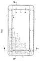
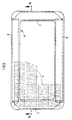
- the solar cells 3 form at mutual distances of about 2 to 5 mm in a regular row arrangement a closed Solar cell field, as shown in FIGS. 1 and 5, in which only some of the solar cells in the solar cell field are drawn.
- FIGS. 1 and 5 show a closed Solar cell field, in which only some of the solar cells in the solar cell field are drawn.
- the solar cell field is only in its outer dimensions little smaller than the free outer surface of the glass sheet 1, so that the outer surface of the glass sheet 1 very largely with solar cells 3 is underlaid, resulting in a high energy yield is achievable.
- the lid has a frame 6 made of a plastic is made of polyurethane, which is molded onto the lid or is foamed. As can be seen from FIGS. 1 to 3 is, the foamed frame 6 covers considerable areas the outer edge area of the solar cell field from below. This is without damaging or destroying the area in question of the solar cell field is only possible if the injection molding and foaming process in the polyurethane plastic occurring pressures are very low.
- the frame 6 is only on the underside of the lid and on the outer edge of the glass pane 1 foamed, so that practically the full outer surface the glass pane 1 is exposed upwards.
- the four frame parts are through foamed rigid paired profile rods 7 and 8 reinforced. Because of the break sensitivity of the solar cells, which is still available in Verbund 5, will be special Measures are taken that have a destructive effect of pressure Prevent profile bars 7 and 8 on the composite 5. These measures consist in that the profile bars 7 and 8 already during the attachment of the frame and of course also in finished lid to the composite 5 are kept at a distance.
- spacers 9 soft material for example made of foam rubber or soft Polyurethane between the facing surfaces of the composite 5 and the profile bars 7 and 8.
- the spacers 9 are the cover 4 from below and are with the profile bars 7 and 8 expediently connected by gluing.
- Fig. 4 are a lower part 10 and an upper part 11 existing molds for foaming the frame 6 shown in the closed state. Since the foam pressure in The shape is low, which can limit the foaming area used seals 12 and 13 also from a soft material, for example sponge rubber. In addition, due to the low foaming pressure, too low form-locking forces required, so that of the seals 12 and 13 and of pressure strips 14 in the upper part 11 of the molds only transfer small forces to the cover be damaging the sensitive solar cells exclude.
- the specially structured seal 13 is in the example shown formed in two parts and consists of a larger sealing body, in the upper groove one in the undeformed Condition in cross section circular foam gasket inserted is.
- the larger seal body can have a Shore A hardness from 40 to 50 and the foam seal one from have about 30.
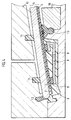
- Fig. 6 shows the situation one side of the lid, which is also related to the mold on the other side is a mirror image.
- the side profile bars have down directed tabs 15, which from the finished frame 6 after protrude below. These tabs have mounting holes 16 for screw bolts and the like to be attached to the cover assembly. This in the profile bars 7 when they are inserted into the mold Existing holes are described to achieve the Spacing between the profile bars 7 and the composite 5 used. For this purpose are in the lower part 10 of the mold holes 17 attached, each with align a receiving bore 16 concentrically.
- the tabs 15 find 18 receptacles in corresponding recesses.
- the Bores 17 are passed transversely through the shape recesses 18.
- a socket pin 19 which is also the Receiving hole 16 penetrated in the tab 15, which over the tab 15 of the profile bar 7 at the required distance is held to Verbund 5.
- the socket pin 19 removed, so that a final formation of the Lid from the lower part 10 of the molds is possible.
- the invention enables one as a solar generator trained cover for motor vehicle sunroofs with foamed plastic frame, in which one with considerable Areas of solar cells reaching into the frame is provided.
- the break-sensitive crystalline solar cells not be damaged. It can therefore be a large area Solar cell field can be accommodated, which at lighter Lid construction enables a high energy yield.
Abstract
Bei einem als Solargenerator ausgebildeten Deckel für Kraftfahrzeug-Schiebedächer mit angeschäumtem Kunststoffrahmen (6) ist ein mit erheblichen Flächenbereichen in den Rahmen (6) hineinreichendes Solarzellenfeld aus kristallinen Solarzellen (3) vorgesehen, wobei durch besondere Maßnahmen sichergestellt ist, daß bei der Umschäumung des Deckels zur Rahmenbildung die bruchempfindlichen kristallinen Solarzellen nicht beschädigt werden. Es kann daher ein flächengroßes Solarzellenfeld untergebracht werden, welches bei leichter Deckelkonstruktion eine hohe Energieausbeute ermöglicht. <IMAGE>In a lid designed as a solar generator for motor vehicle sunroofs with a foamed plastic frame (6), a solar cell field made of crystalline solar cells (3) extending into the frame (6) with considerable surface areas is provided, special measures being taken to ensure that when the lid is foamed around to break the fragile crystalline solar cells are not damaged. An area-sized solar cell field can therefore be accommodated, which enables a high energy yield with a light cover construction. <IMAGE>
Description
Die Erfindung bezieht sich auf einen als Solargenerator ausgebildeten Deckel für Kraftfahrzeug-Schiebedächer, entsprechend dem Oberbegriff des Patentanspruchs 1.The invention relates to a solar generator Lid for motor vehicle sunroofs, accordingly the preamble of claim 1.
Die Bezeichnung "Schiebedächer" wird hier als Sammelbegriff für alle einschlägig bekannten Dachkonstruktionen verstanden, nämlich Schiebedächer mit nur verschiebbarem Deckel, Schiebehebedächer mit sowohl verschiebbarem als auch verschwenkbarem Deckel und Hebedächer mit nur verschwenkbarem Deckel. Auch sogenannte Oberfirstdächer, bei denen der Deckel oberhalb der festen Dachfläche des Kraftfahrzeugs verschiebbar und bei einigen Konstruktionen auch zusätzlich verschwenkbar (Spoilerdach) ist, sollen ebenfalls durch den verwendeten Sammelbegriff erfaßt sein.The term "sunroofs" is used here as a collective term understood for all relevant well-known roof structures, namely sunroofs with only sliding cover, sunroofs with both sliding and pivoting Lid and sunroof with only hinged lid. Also So-called top ridges, where the lid is above the fixed roof surface of the motor vehicle slidable and some constructions can also be pivoted (spoiler roof) is also meant by the collective term used be grasped.
Der bekannte Solargenerator (EP 0 221 287 B1), von dem die vorliegende Erfindung mit dem Oberbegriff des Patentanspruchs 1 ausgeht, ist zwar u.a. für die Verwendung als Schiebedach eines Personenkraftwagens unter Wölbungsanpassung an die aerodynamische Form des Fahrzeugs vorgesehen, jedoch ist die Ausbildung des den Solargenerator in die Schiebedachkonstruktion integrierenden Randbereichs des Verbundes nicht beschrieben.The well-known solar generator (EP 0 221 287 B1), of which the present invention with the preamble of claim 1 goes out, is among other things for use as a sunroof of a passenger car with curvature adjustment to the aerodynamic Form of the vehicle is provided, however, the training of the solar generator in the sunroof construction integrating edge area of the composite is not described.
Es ist auch bekannt (DE 37 37 183 A1), einen Solargenerator, der u.a. zur Verwendung als Solargenerator-Schiebedach eines Personenkraftwagens vorgesehen ist, mit einem Kunststoffrahmen nach einem RIM-Verfahren (Reaction-Injection-Moulding-Verfahren) zu versehen, wobei als Kunststoff ein MehrkomponentenPolyurethanelastomer verwendet wird. Hierbei sind die Solarzellen jedoch beiderseits durch eine starre Platte abgedeckt, nämlich von oben durch eine Glasscheibe und von unten ebenfalls durch eine Glasscheibe oder durch ein Metallblech, wodurch der Deckel eine erhebliche Dicke und dementsprechend ein hohes Gewicht erhält, was bei der Ausbildung der Betätigungselemente für den Deckel mit den daraus resultierenden Nachteilen berücksichtigt werden muß.It is also known (DE 37 37 183 A1), a solar generator, among other things, a passenger vehicle is intended for use as a solar generator sunroof, with a synthetic resin frame according to a RIM process (R eaction- I njection- M oulding method) to provide , where a multi-component polyurethane elastomer is used as plastic. Here, however, the solar cells are covered on both sides by a rigid plate, namely from above through a glass pane and from below also through a glass pane or through a metal sheet, which gives the lid a considerable thickness and, accordingly, a high weight, which is important in the design of the actuators for the lid with the resulting disadvantages must be taken into account.
Entsprechendes gilt für einen bekannten lichtdurchlässigen Deckel mit Solarverbund für Schiebedächer (DE 41 05 389 C1), bei dem der im Außenrandbereich der lichtdurchlässigen Scheibe liegende Teilflächenbereich mit den leistungsstärkeren, aber undurchsichtigen kristallinen Solarzellen und in einem anderen Teilflächenbereich mit leistungsschwächeren, aber durchsichtigen amorphen Solarzellen unterlegt ist. Dieser aus unterschiedlichen Solarzellen zusammengesetzte Solarverbund ist zwischen zwei Glasscheiben eingeschlossen, deren Außenränder von einem Rahmen umgriffen werden, der als Polyurethan-Umschäumung ausgebildet sein kann.The same applies to a known translucent Lid with solar system for sunroofs (DE 41 05 389 C1), in which in the outer edge area of the translucent pane lying partial area with the more powerful, however opaque crystalline solar cells and in another Partial area with less powerful, but transparent amorphous solar cells. This one from different Composite solar cells is composite enclosed between two panes of glass, the outer edges of which to be encompassed by a frame that is used as a polyurethane foam can be trained.
Bei bekannten als Solargenerator ausgebildeten Deckeln, die bereits in Serienautomobile (AUDI A6 und A8) eingebaut werden, wird die innere von dem angeschäumten Kunststoffrahmen umschlossene Fläche des Deckels zur Anordnung von kristallinen Solarzellen benutzt. Da der Kunststoffrahmen aus Festigkeitsgründen und auch wegen der ggf. erforderlichen Unterbringung von Versteifungsprofilen im Rahmen aber verhältnismäßig breite Rahmenteile aufweist, steht nur der innere umrahmte Deckelbereich für die Unterbringung kristalliner Solarzellen zur Verfügung, wodurch die erzielbare Energieausbeute begrenzt ist.In known covers designed as a solar generator, the are already installed in production automobiles (AUDI A6 and A8), the inner one is enclosed by the foamed plastic frame Surface of the lid for the arrangement of crystalline Solar cells used. Because the plastic frame for strength reasons and also because of the necessary accommodation of stiffening profiles in the frame but relatively wide Has frame parts, only the inner framed cover area available for the accommodation of crystalline solar cells, whereby the achievable energy yield is limited.
Eigene Versuche der Anmelderin, kristalline Solarzellen bei einer gattungsgemäßen Solargeneratorausbildung, also bei Verwendung eines leichten Solargenerators mit einer unteren Abdeckfolie, auch im Rahmenbereich unterzubringen und in die Umschäumung einzubeziehen, um dadurch eine höhere Energieausbeute zu erzielen, sind bislang fehlgeschlagen. Es ergab sich eine sehr hohe Bruchrate der Solarzellen bei dem Umschäumungsvorgang. The applicant's own experiments with crystalline solar cells a generic solar generator training, i.e. when used of a light solar generator with a lower one Masking film, also to accommodate in the frame area and in the To include foaming in order to achieve a higher energy yield have so far failed to achieve. It surrendered a very high breakage rate of the solar cells during the foaming process.
Der Erfindung liegt die Aufgabe zugrunde, einen als Solargenerator ausgebildeten Deckel für Kraftfahrzeug-Schiebedächer der eingangs genannten Art bereitzustellen, der bei geringem Gewicht eine vergleichsweise hohe Energieausbeute ermöglicht.The invention has for its object one as a solar generator trained cover for motor vehicle sunroofs Provide initially mentioned type, which is lightweight enables a comparatively high energy yield.
Die gestellte Aufgabe wird durch die Merkmale des Anspruchs 1 gelöst. Vorteilhafte oder zweckmäßige Weiterbildungen ergeben sich aus den Unteransprüchen und sind nachfolgend ebenfalls beschrieben.The object is achieved by the features of claim 1 solved. Advantageous or expedient further developments result derive from the subclaims and are also below described.
Erfindungsgemäß wird die größtmögliche Deckelfläche, d.h. die größtmögliche freie Außenfläche der Glasscheibe, zur Unterbringung von kristallinen Solarzellen ausgenutzt, wodurch ein in seinen Außenabmessungen von der Deckelgröße vorgegebenes maximal großes Solarzellenfeld untergebracht werden kann, welches eine hohe Energieausbeute ermöglicht. Dabei sind die unterseitig nur mit einer Folie abgedeckten elastisch eingebetteten Solarzellen im Außenrandbereich des Solarzellenfeides in die Randumschäumung mit einbezogen, wobei ein gegenüber üblichen RIM-Umschäumungen vergleichsweise geringer Schäumdruck, der gemäß Anspruch 2 < 1 bar ist, und die diesen Druck begleitende vergleichsweise geringere Temperatur die Bruch- und Beschädigungsgefahr für die empfindlichen dünnen kristallinen Solarzellen sehr weitgehend beseitigen. Hierzu trägt auch bei, daß der geringe Druck den Einsatz weicher Dichtungen für die Begrenzung des Schäumbereichs in der Umschäumungsform bei direkter Anlage an die Abdeckfolie und dementsprechend auch geringe Formschließkräfte ermöglicht.According to the invention, the largest possible cover area, i.e. the largest possible free outer surface of the glass pane, for accommodation exploited by crystalline solar cells, resulting in a given in its outer dimensions by the lid size maximum large solar cell field can be accommodated, which enables a high energy yield. Here are the on the underside only covered with a sheet of elastic embedded Solar cells in the outer edge area of the solar cell field included in the edge foam, with one opposite usual RIM foaming comparatively low foam pressure, which is according to claim 2 <1 bar, and this pressure accompanying comparatively lower temperature the fracture and Risk of damage to the delicate thin crystalline Eliminate solar cells to a large extent. This helps also in that the low pressure the use of soft seals for the limitation of the foaming area in the foam encapsulation with direct contact with the cover film and accordingly also allows low form clamping forces.
Zur Vermeidung einer Druckbelastung der Solarzellen durch in den Rahmen eingeschäumte starre Profilstäbe ist gemäß Anspruch 3 vorgesehen, die Profilstäbe gegenüber dem Verbund auf Abstand zu halten.To avoid pressure loading of the solar cells by in the frame foamed rigid profile bars is according to claim 3 provided the profile bars against the composite Keep your distance.
Zu diesem Zweck können entsprechend Anspruch 4 zwischen den Profilstäben und dem Verbund Abstandshalter aus weichem Material eingelegt sein, welche zwischen den Profilstäben und dem Verbund während aller Phasen der Rahmenformung einen ausreichenden Abstand ermöglichen, jedoch selbst keine zerstörende Pressung der Solarzellen hervorrufen. Die Abstandshalter werden bei der Umschäumung eingeschlossen und verbleiben daher im Schaummaterial des Rahmens.For this purpose, according to claim 4 between the Profile bars and the composite spacer made of soft material be inserted, which between the profile bars and the Adequate during all phases of frame shaping Allow distance, but not itself destructive Cause pressing of the solar cells. The spacers will be included in the foaming and therefore remain in the Foam material of the frame.
Alternativ kann gemäß Anspruch 5 die Anordnung auch so getroffen
sein, daß nach dem Umschäumen aus dem Rahmen vorstehende
Laschen gegenüberliegender seitlicher Profilstäbe, die beim
Einbau des Deckels in das Schiebedach dem Angriff von Funktionsteilen
der Deckelbetatigungseinrichtung dienen, als Elemente
zur Abstandshaltung zwischen diesen Profilstäben und dem
Verbund während der Rahmenformung herangezogen werden. Hierbei
liegen die beiden anderen Profilstäbe den über die Flansche
abgestützten seitlichen Profilstäben unmittelbar auf, wodurch
auch zwischen den aufliegenden Profilstäben und dem Verbund
Abstände vorhanden sind. Auch bei dieser Ausgestaltung der den
beschriebenen Abstand herbeiführenden Elemente erfolgt auf den
Verbund und damit auf die empfindlichen Solarzellen keine
Pressung durch Profilstäbe, ohne daß zu diesem Zweck gesonderte
Abstandshalter im Rahmen selbst angeordnet werden müssen.Alternatively, the arrangement can also be made according to
Die Erfindung wird nachfolgend anhand der Ausführungsbeispiele darstellenden Zeichnungen näher erläutert. Darin zeigt:
- Fig. 1
- die Draufsicht auf einen als Solargenerator ausgebildeten Deckel für Kraftfahrzeug-Schiebedächer in einer ersten Ausführungsform,
- Fig. 2
- einen abgebrochenen Schnitt durch den Deckel entlang der Linie II-II in Fig. 1,
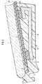
- Fig. 3
- einen abgebrochenen Schnitt durch den Deckel entlang der Linie III-III in Fig. 1,
- Fig. 4
- einen der Fig. 2 entsprechenden abgebrochenen Schnitt durch den Deckel und zusätzlich durch das Formwerkzeug zum Anschäumen des Rahmens an den Deckel,
- Fig. 5
- die Draufsicht auf einen weiteren als Solargenerator ausgebildeten Deckel für Kraftfahrzeugschiebedächer in einer zweiten Ausführungsform und
- Fig. 6
- einen abgebrochenen Schnitt durch den Deckel und zusätzlich durch das Formwerkzeugunterteil zum Anschäumen des Rahmens an den Deckel entlang der Linie VI-VI in Fig. 5.
- Fig. 1
- the top view of a lid designed as a solar generator for motor vehicle sunroofs in a first embodiment,
- Fig. 2
- 2 shows a broken section through the cover along the line II-II in FIG. 1,
- Fig. 3
- 3 shows a broken section through the cover along the line III-III in FIG. 1,
- Fig. 4
- 2 broken section corresponding to FIG. 2 through the cover and additionally through the molding tool for foaming the frame onto the cover,
- Fig. 5
- the top view of another lid designed as a solar generator for motor vehicle sunroofs in a second embodiment and
- Fig. 6
- a broken section through the lid and additionally through the mold bottom part for foaming the frame to the lid along the line VI-VI in Fig. 5th
Die in den beiden Ausführungsformen dargestellten Deckel unterscheiden sich lediglich in der Ausbildung der den Rahmen verstärkenden Profilstäbe und deren Abstandshaltung zum Verbund, so daß zunächst der Deckelaufbau für beide Ausführungsformen anhand der Fig. 1 bis 3 nachfolgend beschrieben wird.The lids shown in the two embodiments differ deal only in the training of the framework reinforcing profile bars and their spacing from the composite, so that first the cover structure for both embodiments 1 to 3 will be described below.
Die Glasscheibe 1 trägt auf ihrer Unterfläche die in ein elastisches Kunststoffmaterial 2 eingebetteten kristallinen Solarzellen 3. Das elastische Kunststoffmaterial 2 besteht ursprünglich aus zwei getrennten Schmelzkleberfolien aus beispielsweise EVA (Ethylen-Vinyl-Acetat-Copolymer), zwischen welche die Solarzellen eingelegt werden. Nach einer Temperatur/Vakuum-Behandlung verschmelzen die beiden Folien zu einer Einbettungsschicht aus dem elastischen Kunststoffmaterial 2, die an der Unterfläche der Glasscheibe 1 fest haftet und nach unten von der Abdeckfolie 4 abgedeckt ist.The glass plate 1 carries on its lower surface embedded in an elastic plastic material 2 crystalline solar cells 3. The elastic plastic material 2 originally consisted of two separate melt adhesive films of, for example, EVA (E thylen- V ynyl A acetate copolymer), between which the solar cells are inserted . After a temperature / vacuum treatment, the two foils fuse to form an embedding layer made of the elastic plastic material 2, which adheres firmly to the lower surface of the glass pane 1 and is covered down by the cover film 4.
Die Glasscheibe 1, das elastische Kunststoffmaterial 2 mit den
darin eingebetteten Solarzellen 3 und die Abdeckfolie bilden
nach ihrer Vereinigung einen einteiligen Verbund 5, der in
dieser Gestalt gelagert, transportiert und schließlich zur
Herstellung des als Solargenerator ausgebildeten Deckels für
Kraftfahrzeug-Schiebedächer mit einer noch zu beschreibenden
Rahmung versehen werden kann.The glass sheet 1, the elastic plastic material 2 with the
embedded solar cells 3 and form the cover sheet
after their union a one-
Die kristallinen Solarzellen 3, die bei einer Dicke von nur etwa 0,1 bis 0,3 mm sehr bruchempfindlich sind, können beispielsweise jeweils Flächenabmessungen von etwa 100 x 100 mm aufweisen. Die einzelnen Zellen sind elektrisch miteinander verbunden und besitzen eine gemeinsame Anschlußbuchse (nicht dargestellt), die zweckmäßig in dem noch zu beschreibenden Rahmen des Deckels untergebracht ist.The crystalline solar cells 3, which have a thickness of only about 0.1 to 0.3 mm are very fragile, for example each area dimensions of about 100 x 100 mm exhibit. The individual cells are electrically interconnected connected and have a common connection socket (not shown), which is useful in the still to be described Frame of the lid is housed.
Die Solarzellen 3 bilden mit gegenseitigen Abständen von etwa 2 bis 5 mm in regelmäßiger Reihenanordnung ein geschlossenes Solarzellenfeld, wie das in den Fig. 1 und 5 dargestellt ist, in welchen nur einige der Solarzellen des Solarzellenfeldes eingezeichnet sind. Wie die Zeichnungen ebenfalls verdeutlichen, ist das Solarzellenfeld in seinen Außenabmessungen nur wenig kleiner als die freie Außenfläche der Glasscheibe 1, so daß die Außenfläche der Glasscheibe 1 sehr weitgehend mit Solarzellen 3 unterlegt ist, wodurch eine hohe Energieausbeute erzielbar ist.The solar cells 3 form at mutual distances of about 2 to 5 mm in a regular row arrangement a closed Solar cell field, as shown in FIGS. 1 and 5, in which only some of the solar cells in the solar cell field are drawn. As the drawings also make clear the solar cell field is only in its outer dimensions little smaller than the free outer surface of the glass sheet 1, so that the outer surface of the glass sheet 1 very largely with solar cells 3 is underlaid, resulting in a high energy yield is achievable.
Der Deckel besitzt einen Rahmen 6, der aus einem Kunststoff
auf Polyurethanbasis besteht, der an den Deckel angespritzt
bzw. angeschäumt ist. Wie aus den Fig. 1 bis 3 ersichtlich
ist, überdeckt der angeschäumte Rahmen 6 erhebliche Flächen
des Außenrandbereichs des Solarzellenfeldes von unten. Dieses
ist ohne Beschädigung oder Zerstörung der betreffenden Flächenbereiche
des Solarzellenfeldes nur möglich, wenn beim Anspritz- und Umschäumungsvorgang die im Polyurethankunststoff
auftretenden Drücke sehr niedrig sind.The lid has a
Wie aus den Fig. 2 und 3 hervorgeht, wird der Rahmen 6 nur an
die Unterseite des Deckels und an die Außenkante der Glasscheibe
1 angeschäumt, so daß praktisch die volle Außenfläche
der Glasscheibe 1 nach oben freiliegt. Am Außenrand des Rahmens
6 befindet sich eine in üblicher Weise ausgestaltete hinterschnittene
Aufnahmeprofilierung für eine Randspaltabdichtung
(nicht dargestellt) des Schiebedachs. Wie bei derartigen
angeschäumten Rahmen üblich, sind die vier Rahmenteile durch
eingeschäumte starre paarweise übereinstimmende Profilstäbe 7
und 8 verstärkt. Wegen der Bruchempfindlichkeit der Solarzellen,
die auch im Verbund 5 noch gegeben ist, werden besondere
Maßnahmen getroffen, die eine zerstörende Druckeinwirkung der
Profilstäbe 7 und 8 auf den Verbund 5 verhindern. Diese Maßnahmen
bestehen darin, daß die Profilstäbe 7 und 8 schon während
der Anbringung des Rahmens und selbstverständlich auch im
fertigen Deckel zu dem Verbund 5 auf Abstand gehalten sind.As can be seen from FIGS. 2 and 3, the
Bei der aus den Fig. 1 bis 4 ersichtlichen Ausführungsform
geschieht dies durch Zwischenlage von Abstandshaltern 9 aus
weichem Material, beispielsweise aus Moosgummi oder weichem
Polyurethan zwischen die zueinander gekehrten Flächen des Verbundes
5 und der Profilstäbe 7 und 8. Die Abstandshalter 9
liegen der Abdeckfolie 4 von unten an und sind mit den Profilstäben
7 und 8 zweckmäßig durch Kleben verbunden.In the embodiment shown in FIGS. 1 to 4
this is done by interposing
In Fig. 4 sind die aus einem Unterteil 10 und einem Oberteil
11 bestehenden Formwerkzeuge für die Anschäumung des Rahmens 6
in geschlossenem Zustand dargestellt. Da der Schäumdruck in
der Form niedrig ist, können die zur Begrenzung des Schäumbereichs
verwendeten Dichtungen 12 und 13 ebenfalls aus einem
weichen Material, beispielsweise Moosgummi, ausgeführt sein.
Außerdem sind aufgrund des geringen Schäumdrucks auch nur
geringe Formschließkräfte erforderlich, so daß von den Dichtungen
12 und 13 sowie von Andruckleisten 14 im Oberteil 11
der Formwerkzeuge nur geringe Kräfte auf den Deckel übertragen
werden, die eine Beschädigung der empfindlichen Solarzellen
ausschließen. Die besonders strukturierte Dichtung 13 ist im
gezeigten Beispiel zweiteilig ausgebildet und besteht aus
einem größeren Dichtkörper, in dessen obere Nut eine im unverformten
Zustand im Querschnitt kreisrunde Schaumdichtung eingelegt
ist. Der größere Dichtungskörper kann eine Shore-A-Härte
von 40 bis 50 und die Schaumdichtung eine solche von
etwa 30 aufweisen.In Fig. 4 are a
Zur Erläuterung der zweiten Ausführungsform des Deckels, d.h.
der Elemente, die den erforderlichen Abstand zwischen den Profilstäben
und dem Verbund sicherstellen, wird nunmehr auf die
Fig. 5 und 6 Bezug genommen. Fig. 6 zeigt die Situation an
einer Seite des Deckels, der auch bezüglich des Formwerkzeugs
an der anderen Seite spiegelbildlich ausgeführt ist. Wie Fig.
6 verdeutlicht, besitzen die seitlichen Profilstäbe nach unten
gerichtete Laschen 15, die aus dem fertigen Rahmen 6 nach
unten vorstehen. Diese Laschen besitzen Aufnahmebohrungen 16
für bei der Deckelmontage anzubringende Schraubbolzen u.dgl.
Diese in den Profilstäben 7 bei ihrer Einlegung in die Form
schon vorhandenen Bohrungen werden zur Erzielung der beschriebenen
Abstandshaltung zwischen den Profilstäben 7 und
dem Verbund 5 herangezogen. Zu diesem Zweck sind im Unterteil
10 der Formwerkzeuge Bohrungen 17 angebracht, die mit jeweils
einer Aufnahmebohrung 16 konzentrisch fluchten. Die Laschen 15
finden in entsprechenden Formausnehmungen 18 Aufnahme. Die
Bohrungen 17 sind quer durch die Formausnehmungen 18 hindurchgeführt.
In jede Bohrung 17 wird nach Einlegung der Profilstäbe
7 ein Steckbolzen 19 eingeführt, der dabei auch die
Aufnahmebohrung 16 in der Lasche 15 durchsetzt, wodurch über
die Lasche 15 der Profilstab 7 in dem erforderlichen Abstand
zum Verbund 5 gehalten wird. Nach der Formung des Rahmens werden
die Steckbolzen 19 entfernt, so daß eine Endformung des
Deckels aus dem Unterteil 10 der Formwerkzeuge möglich ist.To explain the second embodiment of the lid, i.e.
of the elements that the required distance between the profile bars
and ensure the association is now on the
5 and 6 referenced. Fig. 6 shows the situation
one side of the lid, which is also related to the mold
on the other side is a mirror image. As Fig.
6 illustrates, the side profile bars have down
directed
Bei der Ausführungsform der Abstandshaltung gemäß den Fig. 5
und 6 ist weiterhin vorgesehen, daß die Profilstäbe 7 und 8
sich vorn und hinten mit ihren Enden überlappen, so daß die
vorn und hinten am Deckel befindlichen Profilstäbe 8 von den
seitlichen Profilstäben 7 gestützt und damit ebenfalls auf Abstand
zu dem Verbund 5 gehalten werden. In the embodiment of the spacing according to FIG. 5
and 6 is further provided that the profile bars 7 and 8th
their ends overlap at the front and back so that the
Profile bars 8 of the front and rear of the lid
lateral profile bars 7 supported and thus also at a distance
be held to the
Zusammenfassend ermöglicht die Erfindung einen als Solargenerator ausgebildeten Deckel für Kraftfahrzeug-Schiebedächer mit angeschäumtem Kunststoffrahmen, bei welchem ein mit erheblichen Flächenbereichen in den Rahmen hineinreichendes Solarzellenfeld vorgesehen ist. Hierbei wird durch besondere Maßnahmen sichergestellt, daß bei der Umschäumung des Deckels zur Rahmenbildung die bruchempfindlichen kristallinen Solarzellen nicht beschädigt werden. Es kann daher ein flächengroßes Solarzellenfeld untergebracht werden, welches bei leichter Deckelkonstruktion eine hohe Energieausbeute ermöglicht.In summary, the invention enables one as a solar generator trained cover for motor vehicle sunroofs with foamed plastic frame, in which one with considerable Areas of solar cells reaching into the frame is provided. Here, through special measures made sure that when framing the lid to form a frame the break-sensitive crystalline solar cells not be damaged. It can therefore be a large area Solar cell field can be accommodated, which at lighter Lid construction enables a high energy yield.
Sehr wesentlich ist hierbei, daß der Rahmen mit einem vergleichsweise niedrigen Schäumdruck angeschäumt ist. Während bei herkömmlichen RIM-Deckelumschäumungen hohe Schäumdrücke über 10 bar, üblicherweise 12 bar (Hochdruckverfahren), zur Anwendung gelangen, sind Rahmen gemäß der Erfindung mit sehr niedrigen Drücken angeschäumt (Niederdruckverfahren). Rahmen, die mit einem Druck < 1 bar angeschäumt sind, weisen nur eine vernachlässigbar kleine Bruchrate der Solarzellen auf. Der Rahmen kann mit ausgezeichneten Ergebnissen mit einem so niedrigen Druck wie etwa 0,2 bar angeschäumt sein.It is very important that the frame with a comparatively low foam pressure is foamed. While with conventional RIM cover foams high foaming pressures over 10 bar, usually 12 bar (high pressure process), for Applying are frames according to the invention with very foamed at low pressures (low pressure process). Frame, which are foamed with a pressure of <1 bar have only one negligible small breakage rate of the solar cells. Of the Frame can with excellent results with such a low Pressure such as about 0.2 bar.
Claims (5)
Applications Claiming Priority (2)
| Application Number | Priority Date | Filing Date | Title |
|---|---|---|---|
| DE19739615A DE19739615C1 (en) | 1997-09-09 | 1997-09-09 | Solar generator for a vehicle, in the form of a sliding roof |
| DE19739615 | 1997-09-09 |
Publications (2)
| Publication Number | Publication Date |
|---|---|
| EP0901918A2 true EP0901918A2 (en) | 1999-03-17 |
| EP0901918A3 EP0901918A3 (en) | 2000-01-26 |
Family
ID=7841798
Family Applications (1)
| Application Number | Title | Priority Date | Filing Date |
|---|---|---|---|
| EP98116744A Withdrawn EP0901918A3 (en) | 1997-09-09 | 1998-09-04 | Cover incorporating solar cells for a vehicle sliding roof |
Country Status (4)
| Country | Link |
|---|---|
| US (1) | US6034320A (en) |
| EP (1) | EP0901918A3 (en) |
| JP (1) | JP3131188B2 (en) |
| DE (1) | DE19739615C1 (en) |
Cited By (3)
| Publication number | Priority date | Publication date | Assignee | Title |
|---|---|---|---|---|
| EP1245418A3 (en) * | 2001-03-28 | 2003-04-02 | ArvinMeritor GmbH | Panel configured as solar generator to close an opening for vehicle body |
| WO2003041980A2 (en) * | 2001-10-19 | 2003-05-22 | Webasto Vehicle Systems International Gmbh | Glass cover for a vehicle roof and production method therefor |
| EP1336520A1 (en) * | 2002-02-18 | 2003-08-20 | Webasto Vehicle Systems International GmbH | Glass panel for vehicle roofs with anti-shatter foil |
Families Citing this family (22)
| Publication number | Priority date | Publication date | Assignee | Title |
|---|---|---|---|---|
| DE19911811C1 (en) * | 1999-03-17 | 2000-06-21 | Webasto Vehicle Sys Int Gmbh | Solar cell sun roof for vehicle includes solar cell sheet composite clamped between carrier and transparent cover with foam edge seal and bonding |
| US6221290B1 (en) * | 1999-04-23 | 2001-04-24 | Algonquin Industries International, Inc. | Injection molded tonneau cover for pick-up truck |
| ATE246582T1 (en) * | 1999-05-24 | 2003-08-15 | Pilkington Italia Spa | FORMING AN ELASTOMERIC PROFILE TO A WINDOW |
| DE10231227B4 (en) * | 2002-07-11 | 2005-02-10 | Arvinmeritor Gmbh | As a solar generator trained lid for closing an opening in the body of a vehicle |
| DE10329643B4 (en) * | 2003-07-01 | 2016-08-11 | Webasto Ag | Method for producing a lid with a glass pane and electrical functional elements |
| US7484287B2 (en) * | 2004-09-10 | 2009-02-03 | Tokai Kogyo Company Limited | Apparatus for assembling flexible molding main body part and cover part as molding |
| US20070125417A1 (en) * | 2005-12-07 | 2007-06-07 | Solar Electrical Vehicle, Inc. | Solar energy system for hybrid vehicles |
| WO2009060440A1 (en) * | 2007-11-05 | 2009-05-14 | Mor Research Applications Ltd. | Anti-measles cancer immunotherapy |
| DE102009048000A1 (en) * | 2009-10-01 | 2011-09-15 | Bayer Materialscience Ag | Composite made of open-cell rigid foam |
| EP2353907A1 (en) * | 2010-01-27 | 2011-08-10 | Inalfa Roof Systems Group B.V. | Roof panel and method of manufacturing said panel |
| US9088055B2 (en) | 2010-08-06 | 2015-07-21 | International Business Machines Corporation | Mobile power sharing |
| KR101417219B1 (en) * | 2011-11-29 | 2014-07-09 | 엘지이노텍 주식회사 | Solar apparatus |
| JP5714522B2 (en) * | 2012-02-29 | 2015-05-07 | 八千代工業株式会社 | Mounting structure for film-like electrical equipment |
| USD733645S1 (en) | 2013-06-28 | 2015-07-07 | Dow Global Technologies Llc | Corner connector for a photovoltaic module frame |
| USD747262S1 (en) | 2013-06-28 | 2016-01-12 | Dow Global Technologies Llc | Photovoltaic back panel |
| JP6136895B2 (en) | 2013-11-28 | 2017-05-31 | 株式会社豊田自動織機 | Vehicle roof structure |
| JP5907150B2 (en) | 2013-11-28 | 2016-04-20 | 株式会社豊田自動織機 | Vehicle roof structure and vehicle, and method for manufacturing vehicle roof unit |
| EP2995451B1 (en) * | 2014-09-15 | 2022-11-30 | ISOCLIMA S.p.A. | Glass cover |
| DE102014114414A1 (en) * | 2014-10-03 | 2016-04-07 | Bbg Gmbh & Co. Kg | Frame construction for a glass pane and method for its production |
| KR101860346B1 (en) * | 2016-08-17 | 2018-05-23 | 엘지전자 주식회사 | Solar panel and car roof |
| DE102018123268A1 (en) * | 2018-09-21 | 2020-03-26 | Webasto SE | Cover for a vehicle roof of a motor vehicle, roof arrangement for a motor vehicle and method for producing a cover |
| DE102021114031A1 (en) | 2021-05-31 | 2022-12-01 | Webasto SE | Fixed roof element for a vehicle roof, comprising an element of a shading system and method for producing a fixed roof element |
Citations (3)
| Publication number | Priority date | Publication date | Assignee | Title |
|---|---|---|---|---|
| EP0325369A2 (en) * | 1988-01-20 | 1989-07-26 | Siemens Solar Industries L.P. | Photovoltaic module |
| DE4105389C1 (en) * | 1991-02-21 | 1992-06-11 | Webasto-Schade Gmbh, 8031 Oberpfaffenhofen, De | |
| DE4105396A1 (en) * | 1991-02-21 | 1992-09-03 | Webasto Schade Gmbh | Solar panel for roof of vehicle - made of cell layer between outer glass panel and inner metal support |
Family Cites Families (4)
| Publication number | Priority date | Publication date | Assignee | Title |
|---|---|---|---|---|
| DE3538986C3 (en) * | 1985-11-02 | 1994-11-24 | Deutsche Aerospace | Method of manufacturing a solar generator |
| DE3737183A1 (en) * | 1987-11-03 | 1989-05-18 | Licentia Gmbh | Process for producing the frame of a terrestrial solar generator |
| US5207047A (en) * | 1988-05-11 | 1993-05-04 | Herbert Prignitz | Method and apparatus for discharging a foamed material mixture, and the thermal insulation material produced thereby |
| DE4323140A1 (en) * | 1993-06-19 | 1994-12-22 | Webasto Schade Gmbh | Window design for vehicles |
-
1997
- 1997-09-09 DE DE19739615A patent/DE19739615C1/en not_active Expired - Fee Related
-
1998
- 1998-09-04 EP EP98116744A patent/EP0901918A3/en not_active Withdrawn
- 1998-09-09 JP JP10255454A patent/JP3131188B2/en not_active Expired - Fee Related
- 1998-09-09 US US09/150,475 patent/US6034320A/en not_active Expired - Fee Related
Patent Citations (3)
| Publication number | Priority date | Publication date | Assignee | Title |
|---|---|---|---|---|
| EP0325369A2 (en) * | 1988-01-20 | 1989-07-26 | Siemens Solar Industries L.P. | Photovoltaic module |
| DE4105389C1 (en) * | 1991-02-21 | 1992-06-11 | Webasto-Schade Gmbh, 8031 Oberpfaffenhofen, De | |
| DE4105396A1 (en) * | 1991-02-21 | 1992-09-03 | Webasto Schade Gmbh | Solar panel for roof of vehicle - made of cell layer between outer glass panel and inner metal support |
Cited By (5)
| Publication number | Priority date | Publication date | Assignee | Title |
|---|---|---|---|---|
| EP1245418A3 (en) * | 2001-03-28 | 2003-04-02 | ArvinMeritor GmbH | Panel configured as solar generator to close an opening for vehicle body |
| WO2003041980A2 (en) * | 2001-10-19 | 2003-05-22 | Webasto Vehicle Systems International Gmbh | Glass cover for a vehicle roof and production method therefor |
| WO2003041980A3 (en) * | 2001-10-19 | 2003-12-24 | Webasto Vehicle Sys Int Gmbh | Glass cover for a vehicle roof and production method therefor |
| EP1336520A1 (en) * | 2002-02-18 | 2003-08-20 | Webasto Vehicle Systems International GmbH | Glass panel for vehicle roofs with anti-shatter foil |
| EP1336520B2 (en) † | 2002-02-18 | 2014-11-05 | Webasto AG | Glass panel for vehicle roofs with anti-shatter foil |
Also Published As
| Publication number | Publication date |
|---|---|
| DE19739615C1 (en) | 1998-12-17 |
| US6034320A (en) | 2000-03-07 |
| JP3131188B2 (en) | 2001-01-31 |
| EP0901918A3 (en) | 2000-01-26 |
| JPH11157342A (en) | 1999-06-15 |
Similar Documents
| Publication | Publication Date | Title |
|---|---|---|
| DE19739615C1 (en) | Solar generator for a vehicle, in the form of a sliding roof | |
| EP1245418B1 (en) | Panel configured as solar generator to close an opening for vehicle body | |
| DE19852383B4 (en) | Roof module for a vehicle and method of making the same | |
| EP1594692B1 (en) | Window arrangement for a vehicle and method for the production thereof | |
| DE102009011265B4 (en) | All-glass roof for a motor vehicle | |
| DE10163709B4 (en) | Modular vehicle roof | |
| EP1729989A2 (en) | Arrangement for sealing an opening of a vehicle with a window and an anti-splinter element | |
| EP0995667A1 (en) | Composite member for vehicle bodies | |
| EP1669277B1 (en) | Accessory vehicle body part, intermediate product and manufacturing process for such a part | |
| DE69826614T2 (en) | Laminated glass and process for its production | |
| DE102005040061A1 (en) | Automotive component carrier and method of making same | |
| WO2006099858A1 (en) | Method and tool for production of a composite chassis piece for a vehicle | |
| EP1176044B1 (en) | Composite member for vehicle bodies as well as a method and apparatus for the production thereof | |
| EP1036683B1 (en) | Solar panel for a roof opening of an automotive vehicle | |
| EP1729988A2 (en) | Arrangement for sealing an opening in a vehicle with a chipping protector element | |
| DE3702402C2 (en) | Height-adjustable side window made of insulating glass for motor vehicles and process for their production | |
| DE10150011B4 (en) | Cover for a vehicle roof and method for its manufacture | |
| DE102005031884B4 (en) | Method for producing a composite body part for a vehicle | |
| DE102004003328A1 (en) | Curved bodywork component for a vehicle, comprises placing a melt adhesive film on one side of the element, placing cells on the film, and applying another film on top | |
| DE102005029849A1 (en) | Method for manufacturing vehicle body structural element e.g. roof module, roof top cover, by inserting adjacent laminar parts of outer skin into sealing tool, while laminar parts are supported on carrier structure | |
| WO2009019034A1 (en) | Reinforced transparent vehicle panel | |
| DE19819679C1 (en) | Car solar roof | |
| EP2018312B1 (en) | Vehicle roof part comprising at least one plastic layer and a frame connected thereto | |
| DE102015219094A1 (en) | Motor vehicle window pane and method for its production | |
| DE19819680C1 (en) | Easily manufactured vehicle sun-roof solar panel |
Legal Events
| Date | Code | Title | Description |
|---|---|---|---|
| PUAI | Public reference made under article 153(3) epc to a published international application that has entered the european phase |
Free format text: ORIGINAL CODE: 0009012 |
|
| AK | Designated contracting states |
Kind code of ref document: A2 Designated state(s): DE GB |
|
| AX | Request for extension of the european patent |
Free format text: AL;LT;LV;MK;RO;SI |
|
| RIC1 | Information provided on ipc code assigned before grant |
Free format text: 6B 60J 7/043 A, 6B 29C 70/76 B, 6B 29C 44/12 B, 6H 01L 31/048 B, 6H 01L 31/042 - |
|
| PUAL | Search report despatched |
Free format text: ORIGINAL CODE: 0009013 |
|
| AK | Designated contracting states |
Kind code of ref document: A3 Designated state(s): AT BE CH CY DE DK ES FI FR GB GR IE IT LI LU MC NL PT SE |
|
| AX | Request for extension of the european patent |
Free format text: AL;LT;LV;MK;RO;SI |
|
| 17P | Request for examination filed |
Effective date: 20000302 |
|
| AKX | Designation fees paid |
Free format text: DE GB |
|
| 17Q | First examination report despatched |
Effective date: 20020211 |
|
| STAA | Information on the status of an ep patent application or granted ep patent |
Free format text: STATUS: THE APPLICATION IS DEEMED TO BE WITHDRAWN |
|
| 18D | Application deemed to be withdrawn |
Effective date: 20020622 |