EP0901878A1 - Tool carrier for numeric-control machine tools - Google Patents
Tool carrier for numeric-control machine tools Download PDFInfo
- Publication number
- EP0901878A1 EP0901878A1 EP98115999A EP98115999A EP0901878A1 EP 0901878 A1 EP0901878 A1 EP 0901878A1 EP 98115999 A EP98115999 A EP 98115999A EP 98115999 A EP98115999 A EP 98115999A EP 0901878 A1 EP0901878 A1 EP 0901878A1
- Authority
- EP
- European Patent Office
- Prior art keywords
- tool
- tool carrier
- elongated body
- rack
- racks
- Prior art date
- Legal status (The legal status is an assumption and is not a legal conclusion. Google has not performed a legal analysis and makes no representation as to the accuracy of the status listed.)
- Withdrawn
Links
- 239000000969 carrier Substances 0.000 description 4
- 238000003754 machining Methods 0.000 description 3
- 230000009471 action Effects 0.000 description 1
- 230000008901 benefit Effects 0.000 description 1
- 230000008859 change Effects 0.000 description 1
- 230000000670 limiting effect Effects 0.000 description 1
- 230000004048 modification Effects 0.000 description 1
- 238000012986 modification Methods 0.000 description 1
Images
Classifications
-
- B—PERFORMING OPERATIONS; TRANSPORTING
- B23—MACHINE TOOLS; METAL-WORKING NOT OTHERWISE PROVIDED FOR
- B23Q—DETAILS, COMPONENTS, OR ACCESSORIES FOR MACHINE TOOLS, e.g. ARRANGEMENTS FOR COPYING OR CONTROLLING; MACHINE TOOLS IN GENERAL CHARACTERISED BY THE CONSTRUCTION OF PARTICULAR DETAILS OR COMPONENTS; COMBINATIONS OR ASSOCIATIONS OF METAL-WORKING MACHINES, NOT DIRECTED TO A PARTICULAR RESULT
- B23Q3/00—Devices holding, supporting, or positioning work or tools, of a kind normally removable from the machine
- B23Q3/155—Arrangements for automatic insertion or removal of tools, e.g. combined with manual handling
- B23Q3/157—Arrangements for automatic insertion or removal of tools, e.g. combined with manual handling of rotary tools
- B23Q3/15713—Arrangements for automatic insertion or removal of tools, e.g. combined with manual handling of rotary tools a transfer device taking a single tool from a storage device and inserting it in a spindle
- B23Q3/1572—Arrangements for automatic insertion or removal of tools, e.g. combined with manual handling of rotary tools a transfer device taking a single tool from a storage device and inserting it in a spindle the storage device comprising rotating or circulating storing means
- B23Q3/15722—Rotary discs or drums
-
- B—PERFORMING OPERATIONS; TRANSPORTING
- B23—MACHINE TOOLS; METAL-WORKING NOT OTHERWISE PROVIDED FOR
- B23Q—DETAILS, COMPONENTS, OR ACCESSORIES FOR MACHINE TOOLS, e.g. ARRANGEMENTS FOR COPYING OR CONTROLLING; MACHINE TOOLS IN GENERAL CHARACTERISED BY THE CONSTRUCTION OF PARTICULAR DETAILS OR COMPONENTS; COMBINATIONS OR ASSOCIATIONS OF METAL-WORKING MACHINES, NOT DIRECTED TO A PARTICULAR RESULT
- B23Q3/00—Devices holding, supporting, or positioning work or tools, of a kind normally removable from the machine
- B23Q3/155—Arrangements for automatic insertion or removal of tools, e.g. combined with manual handling
- B23Q3/1552—Arrangements for automatic insertion or removal of tools, e.g. combined with manual handling parts of devices for automatically inserting or removing tools
- B23Q3/15526—Storage devices; Drive mechanisms therefor
- B23Q2003/15527—Storage devices; Drive mechanisms therefor the storage device including means to latch tools
Definitions
- the present invention relates to a rack-type tool carrier for numeric-control machine tools.
- Conventional automatic carriers of the drum or rack type are used in order to allow numeric-control machine tools to change tool under the control of the program without interrupting the machining process.
- this is accomplished by rotating the drum until the chosen tool is in a fixed position which can be accessed by the working head or by a swapping arm.
- it is performed by moving the working head along the rack to a position in front of the chosen tool.
- drum-type carriers are bulky and expensive, while rack-type carriers are simple and compact.
- rack-type carriers cannot be longer than the stroke that can be performed by the working head, and this is a limitation which is particularly felt in the case of small machines in which the movements that the head must perform are confined to a limited area.
- the aim of the invention is to increase the number of tools available to the machining program in a numeric-control machine tool, given an equal stroke executable by the working head of the machine, without an appreciable increase in the bulk of the tool carrier.
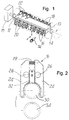
- a tool carrier according to a preferred embodiment of the invention comprises a rigid elongated body 10 which is rotatably supported at its ends on supports 12 and 14 and is turned by an actuator which is schematically designated by the reference numeral 15, for example a hydraulically actuated rack-and-pinion device.
- Respective rows of tool clamps 16 and 18 are mounted along opposite faces of the elongated body 10; each clamp is adapted to grip and retain, in an elastically detachable manner, a respective standard tool such as 20, 22.
- a clamp 16 and 18 comprises, in a per se known manner, two symmetrical jaws 24 which are pivoted at 26 on the body 10 and are actuated elastically by a spring 28 so as to close flexibly around the neck of a standard tool 30.
- a tooth 32 is fixed between the jaws 24 so as to fit in a corresponding notch of the tool to ensure its uniform orientation.
- the carrier is conveniently arranged on a machine tool, not shown, so that the row of clamps 16 is in a position which can be accessed by the working head of the machine tool or by another tool changing element, so that a tool such as 34 can be moved laterally toward an empty clamp and inserted with a snap action in the clamp and so that one of the tools 20 can be picked up laterally, as is known in the field.
- the carrier can be rotated through a half turn so as to swap the two rows of clamps 16 and 18, thus making the tools 22 supported by the row of clamps 18 accessible for swapping with the working head.
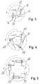
- Figure 4 illustrates a second embodiment of the invention, wherein the carrier has three linear racks with clamps 40, 42 and 44 which are mounted in a triangular arrangement on an elongated body 46 which is rotatably supported exactly like the body 10 of Figures 1 to 3.
- the number of tools in the carrier is tripled with respect to the conventional rack and changing from one rack to the next of course occurs with a rotation through 120° instead of 180° as in the first embodiment.
- Figure 5 illustrates a third embodiment with four racks 46,48,50,52 and therefore with a quadrupled number of tools.
- the racks may of course be five or more, but it is evident that the diametrical size of the carrier increases rapidly as the number of racks increases.
Landscapes
- Engineering & Computer Science (AREA)
- Mechanical Engineering (AREA)
- Warehouses Or Storage Devices (AREA)
- Automatic Tool Replacement In Machine Tools (AREA)
Abstract
A tool carrier for numeric-control machine tools
comprising an elongated body (10) which is rotatably
mounted on a chosen fixed axis and is provided with at
least two tool-holder racks (16, 18) on longitudinal sides
which are angularly mutually spaced in a symmetrical
fashion. A rack-and-pinion device (15) is adapted to rotate
the elongated body to place a chosen rack in a fixed
angular position which can be accessed by a tool changing
element.
Description
- The present invention relates to a rack-type tool carrier for numeric-control machine tools.
- Conventional automatic carriers of the drum or rack type are used in order to allow numeric-control machine tools to change tool under the control of the program without interrupting the machining process. In the first case, this is accomplished by rotating the drum until the chosen tool is in a fixed position which can be accessed by the working head or by a swapping arm. In the second case, it is performed by moving the working head along the rack to a position in front of the chosen tool.
- It is known to the expert in the field that drum-type carriers are bulky and expensive, while rack-type carriers are simple and compact. However, rack-type carriers cannot be longer than the stroke that can be performed by the working head, and this is a limitation which is particularly felt in the case of small machines in which the movements that the head must perform are confined to a limited area.
- The limit to the number of tools accessible on the rack is even more strongly felt in the case of machine tools with a working head provided with two spindles and two worktables, since in this case the tools are changed in pairs, thus halving the assortment of tools available.
- The aim of the invention is to increase the number of tools available to the machining program in a numeric-control machine tool, given an equal stroke executable by the working head of the machine, without an appreciable increase in the bulk of the tool carrier.
- This aim, these objects and others which will become apparent from the following detailed description are achieved by the invention with a tool carrier having the characteristics stated in the appended claims.
- Some preferred embodiments of the invention are now described with reference to the accompanying drawings, wherein:
- Figure 1 is a perspective view of a tool carrier according to a first preferred embodiment of the invention;
- Figure 2 is an enlarged-scale front view of a tool clamp which belongs to the carrier of Figure 1;
- Figure 3 is a side view of the carrier of Figure 1;
- Figure 4 is a view, similar to Figure 3, of a second embodiment of the invention; and
- Figure 5 is a view, similar to Figure 3, of a third embodiment of the invention.
-
- With reference to Figures 1 to 3, a tool carrier according to a preferred embodiment of the invention comprises a rigid
elongated body 10 which is rotatably supported at its ends onsupports reference numeral 15, for example a hydraulically actuated rack-and-pinion device. - Respective rows of
tool clamps elongated body 10; each clamp is adapted to grip and retain, in an elastically detachable manner, a respective standard tool such as 20, 22. - As shown in detail in Figure 2, a
clamp symmetrical jaws 24 which are pivoted at 26 on thebody 10 and are actuated elastically by aspring 28 so as to close flexibly around the neck of astandard tool 30. Atooth 32 is fixed between thejaws 24 so as to fit in a corresponding notch of the tool to ensure its uniform orientation. - The carrier is conveniently arranged on a machine tool, not shown, so that the row of
clamps 16 is in a position which can be accessed by the working head of the machine tool or by another tool changing element, so that a tool such as 34 can be moved laterally toward an empty clamp and inserted with a snap action in the clamp and so that one of thetools 20 can be picked up laterally, as is known in the field. - According to the invention, the carrier can be rotated through a half turn so as to swap the two rows of
clamps tools 22 supported by the row ofclamps 18 accessible for swapping with the working head. - It is evident to the expert in the field that the rotation can easily occur under the control of the program and entails no intervention of the operator or any other kind of interruption of the machining process. In this manner, the number of tools available within the programmed machining is doubled given an equal stroke allowed to the working head. The advantage is particularly appreciable in the case of machine tools with working heads provided with two spindles.
- It is also evident to the expert in the field that the invention entails no significant increase in the volume occupied by the carrier on the machine tool and that the increase in complexity and cost is also low.
- Figure 4 illustrates a second embodiment of the invention, wherein the carrier has three linear racks with
clamps elongated body 46 which is rotatably supported exactly like thebody 10 of Figures 1 to 3. In this case, the number of tools in the carrier is tripled with respect to the conventional rack and changing from one rack to the next of course occurs with a rotation through 120° instead of 180° as in the first embodiment. Figure 5 illustrates a third embodiment with fourracks - The above described preferred embodiments of the invention may be subject to modifications and variations within the scope of the inventive concept. Said variations are to be considered as being within the scope of the protection of the invention to the extent to which they use technically equivalent means to achieve equal results.
- The disclosures in Italian Patent Application No. TO97A000797 from which this application claims priority are incorporated herein by reference.
- Where technical features mentioned in any claim are followed by reference signs, those reference signs have been included for the sole purpose of increasing the intelligibility of the claims and accordingly, such reference signs do not have any limiting effect on the interpretation of each element identified by way of example by such reference signs.
Claims (6)
- A tool carrier for numeric-control machine tools, characterized in that it comprises an elongated body, which is rotatably mounted on a fixed shaft and is provided with at least two tool racks on mutually angularly spaced longitudinal sides, and motor means, which are adapted to turn the elongated body so as to place a chosen rack in a preset fixed angular position.
- The tool carrier according to claim 1, characterized in that it comprises two racks which are mounted in diametrically opposite positions on said elongated body.
- The tool carrier according to claim 1, characterized in that it comprises three racks which are mounted in a triangular configuration on said elongated body.
- The tool carrier according to claim 1, characterized in that it comprises four racks mounted on said elongated body with angular offsets of 90° from each other.
- The tool carrier according to claim 1, characterized in that each tool rack comprises a linear row of tool clamps.
- The tool carrier according to claim 1, characterized in that said motor means are constituted by a hydraulically actuated rack-and-pinion device.
Applications Claiming Priority (2)
| Application Number | Priority Date | Filing Date | Title |
|---|---|---|---|
| ITTO970797 | 1997-09-09 | ||
| IT97TO000797A IT1294850B1 (en) | 1997-09-09 | 1997-09-09 | TOOL-HOLDER WAREHOUSE FOR MACHINES TOOLS WITH NUMERIC CONTROL |
Publications (1)
| Publication Number | Publication Date |
|---|---|
| EP0901878A1 true EP0901878A1 (en) | 1999-03-17 |
Family
ID=11415987
Family Applications (1)
| Application Number | Title | Priority Date | Filing Date |
|---|---|---|---|
| EP98115999A Withdrawn EP0901878A1 (en) | 1997-09-09 | 1998-08-25 | Tool carrier for numeric-control machine tools |
Country Status (2)
| Country | Link |
|---|---|
| EP (1) | EP0901878A1 (en) |
| IT (1) | IT1294850B1 (en) |
Cited By (7)
| Publication number | Priority date | Publication date | Assignee | Title |
|---|---|---|---|---|
| CN103878622A (en) * | 2012-12-19 | 2014-06-25 | 鸿准精密模具(昆山)有限公司 | Tool magazine and machine tool using tool magazine |
| CN104551807A (en) * | 2015-02-03 | 2015-04-29 | 湖北毅兴机床有限公司 | Tool magazine tool clamping device |
| CN109648374A (en) * | 2018-12-29 | 2019-04-19 | 广东长盈精密技术有限公司 | Five-axis robot lathe |
| CN110340707A (en) * | 2018-04-02 | 2019-10-18 | 佛山市佛数科技有限公司 | A rotary tool magazine |
| CN111113115A (en) * | 2020-01-14 | 2020-05-08 | 深圳市环球同创机械有限公司 | A kind of annular multi-row tool magazine and tool supply method |
| EP4000801A1 (en) * | 2020-11-19 | 2022-05-25 | Chen Sound Industrial Co., Ltd. | Drum-type tool magazine adaptive to multi-axis machining center |
| CN114603383A (en) * | 2020-12-09 | 2022-06-10 | 臻赏工业股份有限公司 | Drum magazine for multi-axis machines |
Citations (9)
| Publication number | Priority date | Publication date | Assignee | Title |
|---|---|---|---|---|
| DD78175A (en) * | ||||
| US3715801A (en) * | 1969-03-04 | 1973-02-13 | Y Sato | Tool changer for machine tool |
| GB1341577A (en) * | 1970-08-07 | 1973-12-25 | Dso Zmm Bg | Multi-level tool magazine |
| GB2167325A (en) * | 1984-11-22 | 1986-05-29 | Wavis Engineering Dev Co Limit | Multi-spindle machining centre |
| JPS62102938A (en) * | 1985-10-29 | 1987-05-13 | Mitsubishi Heavy Ind Ltd | Tool storage |
| EP0224714A1 (en) * | 1985-11-06 | 1987-06-10 | Schmoll Maschinen GmbH Werkzeug- und Vorrichtungsbau | Machine tool with a storage board |
| US4920631A (en) * | 1987-10-08 | 1990-05-01 | Starrfraschmachinen, AG. | Tool rack for machine tools |
| EP0483781A2 (en) * | 1990-11-01 | 1992-05-06 | Kitamura Machinery Co.,Ltd. | Tool magazine |
| US5228582A (en) * | 1992-07-01 | 1993-07-20 | Marshall J C | Holder for screws, bolts, nuts and washers |
-
1997
- 1997-09-09 IT IT97TO000797A patent/IT1294850B1/en active IP Right Grant
-
1998
- 1998-08-25 EP EP98115999A patent/EP0901878A1/en not_active Withdrawn
Patent Citations (9)
| Publication number | Priority date | Publication date | Assignee | Title |
|---|---|---|---|---|
| DD78175A (en) * | ||||
| US3715801A (en) * | 1969-03-04 | 1973-02-13 | Y Sato | Tool changer for machine tool |
| GB1341577A (en) * | 1970-08-07 | 1973-12-25 | Dso Zmm Bg | Multi-level tool magazine |
| GB2167325A (en) * | 1984-11-22 | 1986-05-29 | Wavis Engineering Dev Co Limit | Multi-spindle machining centre |
| JPS62102938A (en) * | 1985-10-29 | 1987-05-13 | Mitsubishi Heavy Ind Ltd | Tool storage |
| EP0224714A1 (en) * | 1985-11-06 | 1987-06-10 | Schmoll Maschinen GmbH Werkzeug- und Vorrichtungsbau | Machine tool with a storage board |
| US4920631A (en) * | 1987-10-08 | 1990-05-01 | Starrfraschmachinen, AG. | Tool rack for machine tools |
| EP0483781A2 (en) * | 1990-11-01 | 1992-05-06 | Kitamura Machinery Co.,Ltd. | Tool magazine |
| US5228582A (en) * | 1992-07-01 | 1993-07-20 | Marshall J C | Holder for screws, bolts, nuts and washers |
Non-Patent Citations (1)
| Title |
|---|
| PATENT ABSTRACTS OF JAPAN vol. 11, no. 318 (M - 632) 16 October 1987 (1987-10-16) * |
Cited By (16)
| Publication number | Priority date | Publication date | Assignee | Title |
|---|---|---|---|---|
| JP2014121779A (en) * | 2012-12-19 | 2014-07-03 | Advanced Power Electronics Corp | Cutting tool holder and lathe attached with cutting tool holder |
| EP2745984A3 (en) * | 2012-12-19 | 2015-05-06 | Fu Ding Electronical Technology (Jiashan) Co., Ltd. | Tool magazine |
| CN103878622B (en) * | 2012-12-19 | 2016-08-03 | 鸿准精密模具(昆山)有限公司 | Tool magazine and use the lathe of this tool magazine |
| US9452501B2 (en) | 2012-12-19 | 2016-09-27 | Fu Ding Electronical Technology (Jiashan) Co., Ltd. | Tool magazine and machine using the same |
| CN103878622A (en) * | 2012-12-19 | 2014-06-25 | 鸿准精密模具(昆山)有限公司 | Tool magazine and machine tool using tool magazine |
| CN104551807A (en) * | 2015-02-03 | 2015-04-29 | 湖北毅兴机床有限公司 | Tool magazine tool clamping device |
| CN110340707A (en) * | 2018-04-02 | 2019-10-18 | 佛山市佛数科技有限公司 | A rotary tool magazine |
| CN109648374B (en) * | 2018-12-29 | 2020-06-02 | 广东长盈精密技术有限公司 | Five-axis machining machine |
| CN109648374A (en) * | 2018-12-29 | 2019-04-19 | 广东长盈精密技术有限公司 | Five-axis robot lathe |
| CN111113115A (en) * | 2020-01-14 | 2020-05-08 | 深圳市环球同创机械有限公司 | A kind of annular multi-row tool magazine and tool supply method |
| EP4000801A1 (en) * | 2020-11-19 | 2022-05-25 | Chen Sound Industrial Co., Ltd. | Drum-type tool magazine adaptive to multi-axis machining center |
| KR20220068944A (en) * | 2020-11-19 | 2022-05-26 | 첸 사운드 인더스트리얼 씨오., 엘티디. | Drum-type tool magazine adaptive to multi-axis machining center |
| JP2022081446A (en) * | 2020-11-19 | 2022-05-31 | 臻賞工業股▲ふん▼有限公司 | Drum type tool magazine applied to multi-spindle machining center |
| US11541495B2 (en) * | 2020-11-19 | 2023-01-03 | Chen Sound Industrial Co., Ltd. | Drum-type tool magazine adaptive to multi-axis machining center |
| CN114603383A (en) * | 2020-12-09 | 2022-06-10 | 臻赏工业股份有限公司 | Drum magazine for multi-axis machines |
| CN114603383B (en) * | 2020-12-09 | 2025-04-29 | 臻赏工业股份有限公司 | Drum-type tool magazine for multi-axis machining centers |
Also Published As
| Publication number | Publication date |
|---|---|
| ITTO970797A1 (en) | 1999-03-09 |
| IT1294850B1 (en) | 1999-04-23 |
Similar Documents
| Publication | Publication Date | Title |
|---|---|---|
| US5392501A (en) | Automatic lathe | |
| HK84792A (en) | Magazine with changing device | |
| KR100188751B1 (en) | Tool changer of machining center | |
| US20060225544A1 (en) | Tool support for lathes | |
| JP2003025101A (en) | Machine tools for machining bar-shaped workpieces | |
| JP2003025169A (en) | Machine tool and method for machining bar-shaped workpieces | |
| JPH0356857B2 (en) | ||
| EP0744244B1 (en) | Machine tool for the machining of elongated elements with cantilever-mounted workpiece holder | |
| RU2721758C2 (en) | Machine tool | |
| DE10034973C2 (en) | Universal machine tool with workpiece carriers that can be changed in pick-up mode | |
| US5309368A (en) | Workpiece handling mechanism of a C-N-C lathe machine | |
| US4953274A (en) | Machine tool with two workpiece spindles | |
| US5210917A (en) | Multiple station machine for bar machining | |
| DE3668565D1 (en) | DEVICE FOR DRIVING TOOL CARRIERS IN A MACHINE TOOL. | |
| EP0722677B1 (en) | Brush manufacturing machine and method for manufacturing brushes | |
| KR930004837B1 (en) | Automatic tool changer | |
| DE3902341A1 (en) | GRIPPER OF AN INDUSTRIAL ROBOT | |
| ITTO970797A1 (en) | TOOL-HOLDER WAREHOUSE FOR MACHINES TOOLS WITH NUMERIC CONTROL | |
| FR2364092A1 (en) | Machine tool with indexable turret head - has indexing plate with spindles each with toothed wheel couplable to drive wheel | |
| US20020162431A1 (en) | Structure for a machining center | |
| DE3727684C2 (en) | ||
| RU94006253A (en) | MULTI-PURPOSE MACHINE WITH THE DEVICE OF AUTOMATIC CHANGE OF TOOL | |
| EP1203633B1 (en) | Transfer type machine tool | |
| US5097877A (en) | Machine tool with automatic tool-changing device | |
| JP2566626Y2 (en) | Automatic tool changer for multi-axis machine tools |
Legal Events
| Date | Code | Title | Description |
|---|---|---|---|
| PUAI | Public reference made under article 153(3) epc to a published international application that has entered the european phase |
Free format text: ORIGINAL CODE: 0009012 |
|
| AK | Designated contracting states |
Kind code of ref document: A1 Designated state(s): AT BE CH CY DE DK ES FI FR GB GR IE IT LI LU MC NL PT SE |
|
| AX | Request for extension of the european patent |
Free format text: AL;LT;LV;MK;RO;SI |
|
| STAA | Information on the status of an ep patent application or granted ep patent |
Free format text: STATUS: THE APPLICATION HAS BEEN WITHDRAWN |
|
| 18W | Application withdrawn |
Withdrawal date: 19990510 |