EP0901875A1 - Main de robot pour l'usinage laser de pièces - Google Patents
Main de robot pour l'usinage laser de pièces Download PDFInfo
- Publication number
- EP0901875A1 EP0901875A1 EP98116526A EP98116526A EP0901875A1 EP 0901875 A1 EP0901875 A1 EP 0901875A1 EP 98116526 A EP98116526 A EP 98116526A EP 98116526 A EP98116526 A EP 98116526A EP 0901875 A1 EP0901875 A1 EP 0901875A1
- Authority
- EP
- European Patent Office
- Prior art keywords
- robot
- axis
- hand
- mirror
- laser
- Prior art date
- Legal status (The legal status is an assumption and is not a legal conclusion. Google has not performed a legal analysis and makes no representation as to the accuracy of the status listed.)
- Granted
Links
Images


Classifications
-
- B—PERFORMING OPERATIONS; TRANSPORTING
- B23—MACHINE TOOLS; METAL-WORKING NOT OTHERWISE PROVIDED FOR
- B23K—SOLDERING OR UNSOLDERING; WELDING; CLADDING OR PLATING BY SOLDERING OR WELDING; CUTTING BY APPLYING HEAT LOCALLY, e.g. FLAME CUTTING; WORKING BY LASER BEAM
- B23K26/00—Working by laser beam, e.g. welding, cutting or boring
- B23K26/08—Devices involving relative movement between laser beam and workpiece
- B23K26/0869—Devices involving movement of the laser head in at least one axial direction
- B23K26/0876—Devices involving movement of the laser head in at least one axial direction in at least two axial directions
- B23K26/0884—Devices involving movement of the laser head in at least one axial direction in at least two axial directions in at least in three axial directions, e.g. manipulators, robots
-
- B—PERFORMING OPERATIONS; TRANSPORTING
- B25—HAND TOOLS; PORTABLE POWER-DRIVEN TOOLS; MANIPULATORS
- B25J—MANIPULATORS; CHAMBERS PROVIDED WITH MANIPULATION DEVICES
- B25J19/00—Accessories fitted to manipulators, e.g. for monitoring, for viewing; Safety devices combined with or specially adapted for use in connection with manipulators
- B25J19/0025—Means for supplying energy to the end effector
- B25J19/0029—Means for supplying energy to the end effector arranged within the different robot elements
- B25J19/0037—Means for supplying energy to the end effector arranged within the different robot elements comprising a light beam pathway, e.g. laser
Definitions
- the invention relates to a robot hand with the Features of the preamble of claim 1.
- the invention is therefore based on the object of a robot hand to improve with the features mentioned at the beginning, that the construction effort or the volume of the robot hand is reduced in the area close to the workpiece without affecting the to waive protected radiation supply, moreover however, the robotic hand for use with a variety training from laser sources.
- the axial deflecting mirror easily removed as part of an expansion unit can be.
- the robot hand can follow the expansion of the axial deflection mirror is no longer connected with a central beam feed for the laser radiation be used, however, the possibility for opens a deviating beam feed by an axially parallel one at the location of the removed axial deflecting mirror Radiation passage to the swivel axis mirror available is. Because the axial deflecting mirror is protected inside the robot-side hand axis is also the axially parallel radiation passage to the swivel axis mirror appropriately protected by the robot hand. With that opened the robot hand the possibility of different laser sources to be used without them in the often critical workpiece Area can be significantly redesigned ought to.
- the outer circumference is always the same.
- axis Works are carried out without making any difference Supply of laser radiation or to different Laser should be considered.
- Also installing or replacing the Swivel axis mirror and / or the axis body mirror in With regard to laser radiation of different lasers is not a problem and can with the installation of sensors for a Process monitoring can be linked, with the sensors behind the mirrors.
- the axially parallel radiation passage to the swivel axis mirror can structure all beam cross sections be adapted, which are generated by any lasers.
- the expansion unit to be assembled with the robot-side hand axis can in any case on such radiation penetrations be coordinated with the swivel axis mirror.
- the robot hand can be designed that in the place of the removed axial deflection mirror Connection unit of a fiber optic cable on the robot side Hand axis can be installed.
- a connection unit replaced the expansion unit completely or partially and can be to the Necessities for connecting the light guide cable or different Adjust the light guide cable.
- the connectivity can thus perform an adapter function so that the robot side Hand axis otherwise not specifically for connecting the Optical fiber must be adjusted.
- the robot hand can be designed that the expansion unit is a prismatic body with each other parallel beam passage channels is through a connected this vertical connection channel are, and that the prismatic body the radial and the Axial deflecting mirror with through the interfaces of the channel axes placed reflection surfaces.
- a prismatic one Body as the basic structure of the expansion unit is manufacturing technology easy to manufacture and has the required Precision.
- the radial and the deflecting mirror can with their Reflecting surfaces are arranged exactly parallel and the Parallelism or rectangularity of the channels, also in relation on the surface of the prismatic body on the robot side Hand axis, ensures maximum optical precision.
- a tubular robot-side hand axis is provided on the workpiece side with an end wall on which the expansion unit or the connection unit is attached.
- the End wall of the robot-side hand axis not only forms a desired stabilization in the area near the workpiece Hand axis, but it also enables the expansion unit and / or simply design the connection unit, to be installed in the correct position and fastened securely, without the design effort for the units mentioned would be particularly large.
- the robot hand can be designed so that the tubular robot-side hand axis on a robot-side End flange is rotatably mounted about its longitudinal axis and in the area of the end flange one with the connection unit of the Light guide cable has aligned cable entry. It is as a result, it is possible to use a fiber optic cable To use laser radiation, which is inside the robot Hand axis protected from the end flange to the connection unit is. All dynamic processes take place outside of the robot-side hand axis in an area, which is far away from the workpiece and therefore undisturbed Free space for an optimal, namely stress-minimized Representation of the light guide cable.
- a particularly compact tool results when the Robot hand is designed so that on the end flange Holding device of a laser is attached, the laser radiation the central passage opening on the robot side Hand axis in the area of the end flange via deflecting mirror the holding device is supplied in alignment.
- the laser and the robot using the holding device assembled.
- the result is a handling unit, at which the robot moves with the laser for processing what the total space required for the processing unit very diminished.
- the central opening of the robot-side hand axis whose position changes during rotation the hand axis does not change, allows a problem-free Coupling of the laser radiation into the hand axis. It is the supply of the laser radiation from the laser to the hand axis Deflecting mirror of the holding device possible without any problems.
- the robot hand is designed so that in the A diode laser is installed on the robot-side hand axis Laser beam in the center of the hand axis of the radial deflection mirror the expansion unit or without beam deflection is fed directly to the swivel axis mirror.
- the robot-side hand axis proves to be special versatile because both the expansion unit in conjunction with central beam delivery can be used as well Training where the radiation is direct without beam deflection can be fed to the swivel axis mirror, namely after Expansion of the expansion unit.
- the diode laser could also used in connection with a fiber optic cable be the one between the laser and the axially parallel Radiation passage bridges existing distance and connected to a connection unit of a light cable is.
- a light guide cable is in particular then advantageous if the laser radiation emerges from the diode laser neither with the central axis of the robot side Hand axis is aligned, still with its axis parallel Radiation passage.
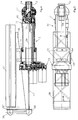
- the robot hand 10 shown in FIG. 1 is a component a machine tool for machining workpieces with Laser radiation.
- the robot hand is part of it, for example of an articulated arm robot, as it is principally used in the DE 43 35 367 has been described.
- Such a robot is like that designed that his robotic hand in all directions of the Cartesian coordinates x, y and z the required movements within the range of its axes can.
- the robot is usually with five axes for that 3-D machining of workpieces.
- Each of the axes has a servomotor for the rotary drive. All actuators are acted upon by a path control so that they initiate the desired axis movements.
- axes of the articulated arm robot are in the drawings two axes are shown in whole or in part. These are a hand axis 12 on the workpiece side and a robot side Hand axis 11.
- the hand axis 12 on the workpiece is by means of an axle body 13 around a vertical one in FIG Swivel axis 17 and the robot-side Hand axis 11 is about a horizontal longitudinal axis in FIG. 1 34 rotatable. A rotation of the hand axis 11 thus causes a corresponding rotation of the hand axis 12.
- the robot-side hand axis 11 of the robot hand 10 exists essentially from a housing tube 42, the workpiece side is provided with an end wall 32.
- the end wall 32 is part of an axle head 42, the with the tubular housing 42 is firmly assembled.
- Of the Axle head 42 is fork-shaped and as a result has two fork arms projecting parallel to the longitudinal axis 34 43.44.
- the axle body 13 installed, which is in contact with the rolling bearings 46 on the fork arm 44 and with the roller bearing 47 on the fork arm 43 pivotally supported.
- the pivotable axle body 13 is opposite the fork arms 43, 44 sealed with seals 48.
- the swivel drive of the hand axis 12 on the workpiece side takes place via a toothing 49 into which a not shown Pinion or worm wheel engages, which in turn is driven in rotation becomes.
- the rotary drive takes place via a rotary tube 50, with its axis body end 50 'to a bearing piece 51 is connected, which is supported in a rotary bearing 52.
- the bearing piece 51 guides those originating from the rotary tube 50 Torques to the bearing shaft 53 in the axle body 13 engaging pinion or worm wheel.
- processing optics 14 are pivoted, that in the figures only schematically by corresponding Mounting and mounting flanges shown has been.
- a module is installed in an adjustable manner contains an optical component, for example a focusing lens.
- the processing optics 14 or such a processing optics processing head, for example a cutting head, is then exactly according to the pivoting of the axis body 13 pivoted about the pivot axis 17.
- the robot-side hand axis 11 has an end flange 33.
- the end flange 33 has a mounting flange 54 shown in FIG Attachment to an arm of the articulated arm robot.
- the mounting flange 54 is parallel to the fork arms 43, 44. It is possible, the robot-side hand axis 11 with a not shown Swivel drive around that shown in Fig. 5 Swivel pivot axis 54 '.
- the tubular housing 42 is also on the end flange 33 a roller bearing 55 rotatably mounted. Another pivot bearing takes place with a roller bearing 56, the inside of a bearing flange 57 receives, which is attached to an inner tube 58, which in turn is integrally connected to the housing 42 is, for example via the fastening ribs 59.
- the rotary drive the hand axis 11 or its housing 42 takes place via a drive motor 60, not shown, whose Torque is transmitted to a drive pinion 61, which is housed in the gear housing 62.
- the drive sprocket 61 drives a manual axis wheel via a reduction stage 63 64, whose axis of rotation coincides with the longitudinal axis 34.
- the hand axis wheel 64 is with the inner tube 58 non-rotatably connected, e.g. via fastening screws 66, with which is also attached to a flange closure plate 65 becomes.
- the flange closure plate 65 thus rotates with the Hand axis wheel 64 when driven by the drive motor 60 becomes. Accordingly, everyone turns with the Flange closure plate 65 connected components, in particular a drive motor 67 for the rotary drive of the rotary tube 50, the end cap end 50 '' with a coupling piece 68 is drivingly connected, which is driven in rotation by the motor 67 becomes. Accordingly, the swivel drive of the Hand axis 12 on the workpiece side by means of the drive motor 67 performed in each rotary setting position of the hand axis 11 even during the adjustment of this robot-side Hand axis 11.
- the flange end plate 65 of the robot-side end flange 33 is provided with a passage opening 41. This is formed centrally, so it encloses the longitudinal axis 34.
- the passage opening 41 is a bore in the flange closure plate 65.
- a bushing 35 installed, which is characterized by the Hand axis wheel 64 extends through into the free space between the end flange 33 and the inner tube 58.
- the articulated arm robot becomes the passage opening 41 and / or the implementation 35 used differently to Laser radiation and / or other inside the hand axis 11 required functional elements in the interior of this hand axis 11 bring in.
- the hand axis 11 offers two ways of supplying radiation, namely the feed through the central passage opening 41 and the feed through the feed-through which is offset radially 35. From these feeds, the laser radiation must get a swivel axis mirror 18, which is in the fork arm 43 of the hand axis 11 is located. Because the area of the swivel axis mirror 18 with an end wall 32 from the inside of the Housing 42 is separated, was in the end wall 32 axially parallel radiation passage 21 to the swivel axis mirror 18 provided.
- the Swivel axis mirror 18 guides the laser radiation striking it parallel to the swivel axis on an axle beam mirror 19, the laser radiation hitting it in the direction the axis 14 '' of the processing optics 14 radiates.
- the mirror 18 is with an adjusting piece 18 'over a mounting flange 18 '' adjustable on fork arm 43.
- the mirror 19 is with an adjusting piece 19 'adjustable on a mounting flange 19 '' of the axle body 13 attached.
- About adjustability the two mirrors 18, 19 in the hand axis 12 become an exact one Setting the beam axis relative to the longitudinal axis 34 and reached to the pivot axis 17. This setting is necessary correct positioning of the laser beam the processing optics with real movements of the robot guarantee.
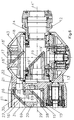
- FIG. 6 shows in detail the design of the robot-side Hand axis 11 near the end wall 32 when the Laser radiation is fed centrally.
- a beam deflection from the longitudinal axis 34 into the radiation passage 21 done.
- There is an expansion unit 20 for this purpose which essentially consists of a prismatic body exists, namely a suitably machined piece of metal.
- the Expansion unit has two parallel beam passage channels 24,25, which is vertical within the unit 20 Have connecting channel 26, all channels being the same, passage cross-section matched to the laser radiation to have.
- the axes 29 to 31 of the channels intersect in interfaces 27, 28 which are in the plane of outer surfaces 69 the unit 20.
- outer surfaces 69 are at 45 ° the channel axes 29 to 31 and each carry one Radial deflecting mirror 15 and an axial deflecting mirror 16. Accordingly are the mirror surfaces of the mirrors 15, 16 with the outer surfaces 69 of the unit 20 and reflect the laser radiation through their channels 24 to 26.
- the on the Radial deflecting mirror 15 hits laser radiation Axial deflecting mirror 16 and from this through the radiation passage 21 to the swivel axis mirror 18.
- the installation of the Removal unit 20 is carried out by abutting the end wall 32 with correspondingly shown pinning, but without adjustment. For the adjustment, the adjustability is the Mirror 18.19 sufficient.
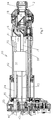
- FIG. 4 shows the use of the robot hand 10 with a CO 2 laser 37 when using an expansion unit 20 within the robot-side hand axis 11.
- the laser 37 is carried by a holding device 36 which is attached to mounting flanges 70 of the end flange 33 of the hand axis 11. Accordingly, the laser 37 is not rotated when the hand axis 11 is rotated or when the housing 42 is rotated. Rather, the laser 37 is only moved to the extent of the movement of the end flange 33, the movements of which are initiated via the flange 54.
- the holding device 36 is aligned together with the laser 37 parallel to the hand axis 11 and overlaps this up to the vicinity of the end wall 32, so that there is a compact design of the laser and articulated arm robot in the area close to the workpiece.
- the robot hand 10 and the holding device 36 with the laser 37 lie in a preferred vertical plane.
- the supervision of Fig.5 shows that the unit builds narrow when a slim laser is used. All elements that serve to couple the laser radiation generated by the laser 37 into the interior of the hand axis 11 are included in the compact design.
- deflection mirrors 38 are used, which deflect the laser radiation generated parallel to the longitudinal axis 34 into the axis 34, for which purpose they are attached to a plate 36 'attached to the holding device 36 and facing away from the workpiece, namely once at the level of the longitudinal axis of the laser 37 and on the other Height of the longitudinal axis 34.
- the laser radiation passes through a tube 71 and the central passage opening 41 of the flange closure plate 65 to the radial deflection mirror 15.
- the robot hand 10 can also be used in conjunction with an Nd: YAG laser.
- Nd: YAG lasers can be used in conjunction with fiber optic cables, since these allow a largely loss-free transmission of this laser light.
- Such a light guide cable is inserted into the interior of the housing 42 through a bushing 35 designed as a cable bushing.
- the end of the light guide cable 23 is fastened to the end wall 32 with the connector 22 shown in FIGS.
- the connection unit 22 has an insertion end 22 'which fits into the radiation passage 21 and is fastened to the end wall 32 with its flange 22', for example by screwing.
- the bore 22 ''' is used to install the end of the light guide cable 23.
- connection unit 22 takes the place of the axial deflection mirror 16, which was removed before the installation of the connection unit 22 by removing the removal unit 20, so that the installation of the connection 22 became possible .
- the space required by the expansion unit 20 within the hand axis 11 remains free.
- the light guide cable 23 is protected within the housing 42 and all movements of the light guide cable necessary as a result of the movements of the robot hand 10 take place outside the robot hand 10. If the Nd: YAG laser can be assembled with the holding device 36, as was shown in FIG. 4 for the CO 2 laser, the deflection mirrors 38 and protective tubes required there are omitted and can be replaced by the light guide cable 23.
- Fig. 7 shows a further variant of the use of the robot hand 10 in conjunction with another laser, namely a diode laser 39.
- the diode laser 39 is in the housing 42 installed and rigidly attached here, so also immobile with respect to the end wall 32.
- the one produced by this laser 39 Laser radiation emerges centrally, i.e. runs in the Longitudinal axis 34 and meets the radial deflecting mirror 15 of the Removal unit 20.
- This is designed as described in Fig.6 and accordingly directs the laser radiation to the processing optics 14.
- the laser 39 can also be designed in this way be that the laser radiation generated by him without Use of the expansion unit 20 is used.
- the removal unit 20 is removed and the laser radiation is replaced by the 16 existing axially parallel radiation passage 21 on the Swivel axis mirror 18 steered.
- the laser beam 72 this Laser radiation is that.
- Such axis parallelism can also be deviated by an output 39 ' a diode laser 39 in a manner not shown with a Light guide cable is fed to the radiation passage 21, which is why, for example, with a connection unit 22 to the End wall 32 is connected.
- the design of the optical components of the robot hand axis 10 can be based on the circumstances required be adjusted.
- the wavelength of the Mirror materials adapted to laser radiation can be used.
Landscapes
- Engineering & Computer Science (AREA)
- Physics & Mathematics (AREA)
- Optics & Photonics (AREA)
- Robotics (AREA)
- Mechanical Engineering (AREA)
- Plasma & Fusion (AREA)
- Laser Beam Processing (AREA)
- Manipulator (AREA)
Applications Claiming Priority (2)
| Application Number | Priority Date | Filing Date | Title |
|---|---|---|---|
| DE29716121U | 1997-09-09 | ||
| DE29716121U DE29716121U1 (de) | 1997-09-09 | 1997-09-09 | Roboterhand für die Bearbeitung von Werkstücken mit Laserstrahlung |
Publications (3)
| Publication Number | Publication Date |
|---|---|
| EP0901875A1 true EP0901875A1 (fr) | 1999-03-17 |
| EP0901875B1 EP0901875B1 (fr) | 2001-08-08 |
| EP0901875B8 EP0901875B8 (fr) | 2002-01-09 |
Family
ID=8045707
Family Applications (1)
| Application Number | Title | Priority Date | Filing Date |
|---|---|---|---|
| EP98116526A Expired - Lifetime EP0901875B8 (fr) | 1997-09-09 | 1998-09-01 | Main de robot pour l'usinage laser de pièces |
Country Status (3)
| Country | Link |
|---|---|
| EP (1) | EP0901875B8 (fr) |
| AT (1) | ATE203946T1 (fr) |
| DE (2) | DE29716121U1 (fr) |
Cited By (6)
| Publication number | Priority date | Publication date | Assignee | Title |
|---|---|---|---|---|
| DE10126871C1 (de) * | 2001-06-01 | 2002-11-14 | Thyssen Laser Technik Gmbh | Verfahren und Vorrichtung zum robotergesteuerten Schneiden von zu fügenden Werkstücken mit Laserstrahlung |
| US6563083B2 (en) | 2000-12-18 | 2003-05-13 | Thyssen Laser-Technik Gmbh | Laser robot for workpiece machining and method for workpiece machining with a laser robot |
| DE10261592B3 (de) * | 2002-12-24 | 2004-10-28 | Reis Gmbh & Co. Maschinenfabrik | Knickarmroboter |
| DE102004051225A1 (de) * | 2004-10-20 | 2006-05-04 | Robot-Technology Gmbh | Roboter und Verfahren zur Steuerung eines Roboters |
| DE10157890B4 (de) * | 2001-11-26 | 2008-06-19 | Alpha Laser Gmbh | Laserbearbeitungsvorrichtung |
| EP2342042B1 (fr) | 2008-09-05 | 2017-11-08 | Renishaw Plc. | Appareil de production supplémentaire à chambre et module optique monté amovible, procédé de préparation d'un appareil de traitement au laser utilisant ledit module optique monté amovible |
Families Citing this family (1)
| Publication number | Priority date | Publication date | Assignee | Title |
|---|---|---|---|---|
| DE20021369U1 (de) * | 2000-12-18 | 2002-05-02 | Thyssen Laser Technik Gmbh | Laserstrahloptik in einer Roboterachse |
Citations (2)
| Publication number | Priority date | Publication date | Assignee | Title |
|---|---|---|---|---|
| US4855565A (en) * | 1986-03-25 | 1989-08-08 | Laser Lab Limited | Work head device |
| DE4335367A1 (de) * | 1992-10-20 | 1994-04-21 | Thyssen Laser Technik Gmbh | Roboterhand für die 3-D-Bearbeitung von Werkstücken |
Family Cites Families (2)
| Publication number | Priority date | Publication date | Assignee | Title |
|---|---|---|---|---|
| US4539462A (en) * | 1983-01-24 | 1985-09-03 | Westinghouse Electric Corp. | Robotic laser beam delivery apparatus |
| SE455925B (sv) * | 1985-07-03 | 1988-08-22 | Asea Ab | Robothandled |
-
1997
- 1997-09-09 DE DE29716121U patent/DE29716121U1/de not_active Expired - Lifetime
-
1998
- 1998-09-01 EP EP98116526A patent/EP0901875B8/fr not_active Expired - Lifetime
- 1998-09-01 AT AT98116526T patent/ATE203946T1/de active
- 1998-09-01 DE DE59801154T patent/DE59801154D1/de not_active Expired - Lifetime
Patent Citations (2)
| Publication number | Priority date | Publication date | Assignee | Title |
|---|---|---|---|---|
| US4855565A (en) * | 1986-03-25 | 1989-08-08 | Laser Lab Limited | Work head device |
| DE4335367A1 (de) * | 1992-10-20 | 1994-04-21 | Thyssen Laser Technik Gmbh | Roboterhand für die 3-D-Bearbeitung von Werkstücken |
Cited By (12)
| Publication number | Priority date | Publication date | Assignee | Title |
|---|---|---|---|---|
| US6563083B2 (en) | 2000-12-18 | 2003-05-13 | Thyssen Laser-Technik Gmbh | Laser robot for workpiece machining and method for workpiece machining with a laser robot |
| US6795482B2 (en) | 2000-12-18 | 2004-09-21 | Thyssen Laser-Technik Gmbh | Laser beam optics in a robot link |
| DE10161175B4 (de) * | 2000-12-18 | 2005-01-05 | Thyssen Laser-Technik Gmbh | Laserstrahloptik in einer Roboterachse |
| DE10126871C1 (de) * | 2001-06-01 | 2002-11-14 | Thyssen Laser Technik Gmbh | Verfahren und Vorrichtung zum robotergesteuerten Schneiden von zu fügenden Werkstücken mit Laserstrahlung |
| WO2002098597A1 (fr) * | 2001-06-01 | 2002-12-12 | Thyssen Laser-Technik Gmbh | Procede et dispositif pour la decoupe commandee par robot de pieces a assembler par rayonnement laser |
| US7248940B2 (en) | 2001-06-01 | 2007-07-24 | Thyssen Laser-Technik Gmbh | Method and device for the robot-controlled cutting of workpieces to be assembled by means of laser radiation |
| DE10157890B4 (de) * | 2001-11-26 | 2008-06-19 | Alpha Laser Gmbh | Laserbearbeitungsvorrichtung |
| DE10261592B3 (de) * | 2002-12-24 | 2004-10-28 | Reis Gmbh & Co. Maschinenfabrik | Knickarmroboter |
| DE102004051225A1 (de) * | 2004-10-20 | 2006-05-04 | Robot-Technology Gmbh | Roboter und Verfahren zur Steuerung eines Roboters |
| DE102004051225B4 (de) * | 2004-10-20 | 2010-06-17 | Robot-Technology Gmbh | Roboter und Verfahren zur Steuerung eines Roboters |
| DE102004051225C5 (de) * | 2004-10-20 | 2012-05-24 | Robot-Technology Gmbh | Roboter und Verfahren zur Steuerung eines Roboters |
| EP2342042B1 (fr) | 2008-09-05 | 2017-11-08 | Renishaw Plc. | Appareil de production supplémentaire à chambre et module optique monté amovible, procédé de préparation d'un appareil de traitement au laser utilisant ledit module optique monté amovible |
Also Published As
| Publication number | Publication date |
|---|---|
| EP0901875B8 (fr) | 2002-01-09 |
| ATE203946T1 (de) | 2001-08-15 |
| DE29716121U1 (de) | 1999-01-14 |
| EP0901875B1 (fr) | 2001-08-08 |
| DE59801154D1 (de) | 2001-09-13 |
Similar Documents
| Publication | Publication Date | Title |
|---|---|---|
| DE19745929C1 (de) | Schweißeinrichtung für zwei über eine in sich geschlossene Schweißnaht miteinander zu verbindende Werkstücke | |
| EP1607167B1 (fr) | Sytème cross-jet pour soudage laser hybride | |
| DE19948895B4 (de) | Laserschweisseinrichtung | |
| EP3484656B1 (fr) | Procédé et machine d'usinage au laser pour le soudage au laser d'une section d'une première et d'une seconde pièce | |
| EP0284921B1 (fr) | Dispositif pour conduir des rayons optiques | |
| DE3402099A1 (de) | Manipulatorgeraet mit licht/laserstrahl | |
| EP0958884A1 (fr) | Procédé d'usinage de pièces ainsi que machine-outil | |
| DE4335367C2 (de) | Roboterhand für die 3-D-Bearbeitung von Werkstücken | |
| EP0901875B1 (fr) | Main de robot pour l'usinage laser de pièces | |
| EP2476504B1 (fr) | Dispositif de traitement | |
| DE19636458C1 (de) | Manuell zu positionierende und zu betätigende Einrichtung zum Laserstrahlschweißen | |
| EP0892692B1 (fr) | Dispositif de soudage et/ou de coupe | |
| EP1433576B1 (fr) | Robot de type à bras articulé muni d'un laser disposé au niveau de son deuxième axe | |
| DE202017101590U1 (de) | Vorrichtung zur Führung eines Laserstrahls auf einn Werkstück | |
| DE10161175B4 (de) | Laserstrahloptik in einer Roboterachse | |
| DE3603033C2 (fr) | ||
| EP3475022A1 (fr) | Unité d'usinage pour usiner une pièce au moyen d'un faisceau d'usinage thermique, comprenant un dispositif d'accouplement | |
| WO2005030427A1 (fr) | Procede d'usinage au laser, en particulier de soudage au laser de composants | |
| EP0722806B1 (fr) | Dispositif de soudage au laser | |
| DE3117606A1 (de) | "automatisch, beruehrungslose brennerfuehrung auf fugenmitte beim schutzgas-lichtbogenschweissen" | |
| DE102005016734A1 (de) | Bearbeitungssystem mit einem Bearbeitungsroboter | |
| DE4139510A1 (de) | Vielgelenkiger laserbearbeitungsroboter | |
| EP0612581B1 (fr) | Tête de soudage | |
| WO2003035318A1 (fr) | Dispositif et procede de brasage par faisceau laser, notamment brasage fort par faisceau laser | |
| DE102005023985A1 (de) | Laserschweißvorrichtung |
Legal Events
| Date | Code | Title | Description |
|---|---|---|---|
| PUAI | Public reference made under article 153(3) epc to a published international application that has entered the european phase |
Free format text: ORIGINAL CODE: 0009012 |
|
| AK | Designated contracting states |
Kind code of ref document: A1 Designated state(s): AT DE FR IT |
|
| AX | Request for extension of the european patent |
Free format text: AL;LT;LV;MK;RO;SI |
|
| 17P | Request for examination filed |
Effective date: 19990310 |
|
| RIN1 | Information on inventor provided before grant (corrected) |
Inventor name: KROTH, EBERHARD, DR.-ING. Inventor name: FISCHER, AXEL, DIPL.-ING., Inventor name: SEILER, STEFAN, DIPL.-ING., Inventor name: NEUMANN, GUENTER Inventor name: KLEIN, ROLF, DR.-ING. |
|
| AKX | Designation fees paid |
Free format text: AT DE FR IT |
|
| GRAG | Despatch of communication of intention to grant |
Free format text: ORIGINAL CODE: EPIDOS AGRA |
|
| 17Q | First examination report despatched |
Effective date: 20001005 |
|
| GRAG | Despatch of communication of intention to grant |
Free format text: ORIGINAL CODE: EPIDOS AGRA |
|
| GRAH | Despatch of communication of intention to grant a patent |
Free format text: ORIGINAL CODE: EPIDOS IGRA |
|
| GRAH | Despatch of communication of intention to grant a patent |
Free format text: ORIGINAL CODE: EPIDOS IGRA |
|
| GRAA | (expected) grant |
Free format text: ORIGINAL CODE: 0009210 |
|
| AK | Designated contracting states |
Kind code of ref document: B1 Designated state(s): AT DE FR IT |
|
| REF | Corresponds to: |
Ref document number: 203946 Country of ref document: AT Date of ref document: 20010815 Kind code of ref document: T |
|
| REF | Corresponds to: |
Ref document number: 59801154 Country of ref document: DE Date of ref document: 20010913 |
|
| ITF | It: translation for a ep patent filed |
Owner name: STUDIO TORTA S.R.L. |
|
| RAP2 | Party data changed (patent owner data changed or rights of a patent transferred) |
Owner name: REIS GMBH & CO Owner name: THYSSEN LASER-TECHNIK GMBH |
|
| ET | Fr: translation filed |
Owner name: REIS GMBH & CO |
|
| PLBE | No opposition filed within time limit |
Free format text: ORIGINAL CODE: 0009261 |
|
| STAA | Information on the status of an ep patent application or granted ep patent |
Free format text: STATUS: NO OPPOSITION FILED WITHIN TIME LIMIT |
|
| RAP4 | Party data changed (patent owner data changed or rights of a patent transferred) |
Owner name: REIS GMBH & CO Owner name: THYSSEN LASER-TECHNIK GMBH |
|
| 26N | No opposition filed |
Opponent name: REIS GMBH & CO |
|
| REG | Reference to a national code |
Ref country code: FR Ref legal event code: TP |
|
| PGFP | Annual fee paid to national office [announced via postgrant information from national office to epo] |
Ref country code: AT Payment date: 20100914 Year of fee payment: 13 |
|
| REG | Reference to a national code |
Ref country code: AT Ref legal event code: MM01 Ref document number: 203946 Country of ref document: AT Kind code of ref document: T Effective date: 20110901 |
|
| PG25 | Lapsed in a contracting state [announced via postgrant information from national office to epo] |
Ref country code: AT Free format text: LAPSE BECAUSE OF NON-PAYMENT OF DUE FEES Effective date: 20110901 |
|
| REG | Reference to a national code |
Ref country code: FR Ref legal event code: PLFP Year of fee payment: 19 |
|
| REG | Reference to a national code |
Ref country code: FR Ref legal event code: PLFP Year of fee payment: 20 |
|
| PGFP | Annual fee paid to national office [announced via postgrant information from national office to epo] |
Ref country code: FR Payment date: 20170714 Year of fee payment: 20 Ref country code: DE Payment date: 20170830 Year of fee payment: 20 Ref country code: IT Payment date: 20170925 Year of fee payment: 20 |
|
| REG | Reference to a national code |
Ref country code: DE Ref legal event code: R071 Ref document number: 59801154 Country of ref document: DE |