EP0901868A1 - Resistance spot welding machine - Google Patents
Resistance spot welding machine Download PDFInfo
- Publication number
- EP0901868A1 EP0901868A1 EP98115704A EP98115704A EP0901868A1 EP 0901868 A1 EP0901868 A1 EP 0901868A1 EP 98115704 A EP98115704 A EP 98115704A EP 98115704 A EP98115704 A EP 98115704A EP 0901868 A1 EP0901868 A1 EP 0901868A1
- Authority
- EP
- European Patent Office
- Prior art keywords
- drive
- resistance pressure
- welding machine
- machine according
- electrode
- Prior art date
- Legal status (The legal status is an assumption and is not a legal conclusion. Google has not performed a legal analysis and makes no representation as to the accuracy of the status listed.)
- Withdrawn
Links
Images


Classifications
-
- B—PERFORMING OPERATIONS; TRANSPORTING
- B23—MACHINE TOOLS; METAL-WORKING NOT OTHERWISE PROVIDED FOR
- B23K—SOLDERING OR UNSOLDERING; WELDING; CLADDING OR PLATING BY SOLDERING OR WELDING; CUTTING BY APPLYING HEAT LOCALLY, e.g. FLAME CUTTING; WORKING BY LASER BEAM
- B23K11/00—Resistance welding; Severing by resistance heating
- B23K11/24—Electric supply or control circuits therefor
- B23K11/25—Monitoring devices
- B23K11/252—Monitoring devices using digital means
- B23K11/257—Monitoring devices using digital means the measured parameter being an electrical current
-
- B—PERFORMING OPERATIONS; TRANSPORTING
- B23—MACHINE TOOLS; METAL-WORKING NOT OTHERWISE PROVIDED FOR
- B23K—SOLDERING OR UNSOLDERING; WELDING; CLADDING OR PLATING BY SOLDERING OR WELDING; CUTTING BY APPLYING HEAT LOCALLY, e.g. FLAME CUTTING; WORKING BY LASER BEAM
- B23K11/00—Resistance welding; Severing by resistance heating
- B23K11/30—Features relating to electrodes
- B23K11/31—Electrode holders and actuating devices therefor
Definitions
- Industrial robots for the Resistance pressure welding consists of a column and arm. At the end of Arms is the welding tool with a suitable mounting flange or the welding gun attached. To a certain point of the Approaching the welding workpiece is first the Welding gun moved to the coordinates X, Y, Z of the point. There Electrodes at any point in a position perpendicular to the Workpiece surface must be arranged with the Welding guns by turning, turning, etc. two to three more Movements necessary. As a result, the kinematics of the Industrial robot setting after 5 to 7 degrees of freedom enable.
Landscapes
- Engineering & Computer Science (AREA)
- Mechanical Engineering (AREA)
- Resistance Welding (AREA)
Abstract
Description
Die Erfindung betrfft eine Widerstandspreßschweißmaschine, bestehend aus mindestens einem Schweißkopf mit einer Elektrode, mindestens einem Schweißtransformator zum Erzeugen eines Schweißstromes, der mit der Elektrode verbunden ist, mindestens einem Antrieb zum Verfahren der Elektrode oder zum Erzeugen eines Elektrodendruckes auf dem Werkstück und einer Steuerung, die mit dem Antrieb und dem Schweißtransformator verbunden ist.The invention relates to a resistance pressure welding machine, consisting of at least one welding head with an electrode, at least one welding transformer for generating a Welding current, which is connected to the electrode, at least one Drive for moving the electrode or for generating a Electrode pressure on the workpiece and a control system with the drive and the welding transformer is connected.
Beim Widerstandspreßschweißen entsteht die Wärme für den Schweißpunkt durch gleichzeitige Einwirkung eines elektrischen Stromes und der Elektrodenkraft sowie dem elektrischen Widerstand der zu verschweißenden Werkstoffe im Bereich der Berührungsstelle der Elektroden. Die Werkstücke liegen in der Regel flach aufeinander und werden durch die Elektrodenkraft unter erheblichen Druck in einzelnen Punkten geschweißt. Der Strom und die Elektrodenkraft wird über die Elektroden zugeführt.Resistance pressure welding generates heat for the Spot weld due to the simultaneous action of an electrical Current and the electrode force as well as the electrical resistance of the materials to be welded in the area of the contact point of the electrodes. The workpieces are usually flat on top of each other and are under considerable pressure by the electrode force individual points welded. The electricity and the electrode power will supplied via the electrodes.
Bekannte Widerstandspreßschweißmaschinen sind als Ein- oder Mehrphasen-Maschinen ausgebildet. Die Betätigung (Vorschub) der beweglichen Elektrode und die Aufbringung des Elektrodendruckes auf das Werkstück erfolgt durch pneumatische Zylinder. Nur in seltenen Fällen werden zum Aufbringen der Elektrodenkraft andere Antriebe, wie zum Beispiel Hydraulikzylinder und mechanische Verstellungen (zum Beispiel Nockenwellen) eingesetzt.Known resistance pressure welding machines are as single or Multi-phase machines trained. The actuation (feed) of the movable electrode and the application of the electrode pressure the workpiece is carried out by pneumatic cylinders. Only in rare Cases are used to apply the electrode force to other drives, such as for example hydraulic cylinders and mechanical adjustments (for Example camshafts) used.
Darüber hinaus werden als Träger von beweglichen Schweißzeugen und Schweißzangen Industrieroboter eingesetzt und in einer Reihe von Richtungen nach festgelegten und gespeicherten Programm entlang der zu schweißenden Kanten der Fügeteile von Punkt zu Punkt bewegt. An jeder vorgesehenen Schweißstelle wird die Schweilßzange durch einen Steuerimpuls zum Punktschweißen gebracht. Industrieroboter für das Widerstandspreßschweißen besteht aus Säule und Arm. Am Ende des Arms ist über einen geeigneten Befestigungsflansch das Schweißzeug bzw. die Schweißzange befestigt. Um einen bestimmten Punkt des zu schweißenden Werkstücks anzufahren, wird zunächst die Schweißzange in die Koordinaten X, Y, Z des Punktes gefahren. Da Elektroden in jedem Punkt in einer Stellung senkrecht zur Werkstückoberfläche angeordnet werden müssen, sind bei den Schweißzangen noch durch Drehen, Wenden usw. zwei bis drei weitere Bewegungen notwendig. Dadurch muß die Kinematik der Industrieroboter die Einstellung nach 5 bis 7 Freiheitsgraden ermöglichen.They are also used as carriers of movable welding tools and welding guns used in a number of industrial robots Directions according to defined and saved program along the edges of the parts to be welded moved from point to point. On the welding gun is replaced by a Control pulse brought to spot welding. Industrial robots for the Resistance pressure welding consists of a column and arm. At the end of Arms is the welding tool with a suitable mounting flange or the welding gun attached. To a certain point of the Approaching the welding workpiece is first the Welding gun moved to the coordinates X, Y, Z of the point. There Electrodes at any point in a position perpendicular to the Workpiece surface must be arranged with the Welding guns by turning, turning, etc. two to three more Movements necessary. As a result, the kinematics of the Industrial robot setting after 5 to 7 degrees of freedom enable.
Diese Bewegungen, elektromotorisch, hydraulisch oder pneumatisch durchgeführt, werden durch eine programmierte Steuerung für jeden Schweißpunkt eingeleitet.These movements, electric motor, hydraulic or pneumatic are carried out by a programmed control system for everyone Weld spot initiated.
Bei den bekannten Widerstandspreßschweißvorrichtungen ist dabei die Regeleinrichtung für die Elektrodenkraft getrennt von der Einrichtung zur Erzeugung des Elektrodenhubes. Eine hochgenaue, gesteuerte bzw. geregelte Bewegung bzw. Positionierung der Elektroden und der Elektrodenkraft in Abhängigkeit von der jeweiligen Position wäre jedoch wünschenswert. In the known resistance pressure welding devices is the Control device for the electrode force separately from the device to generate the electrode stroke. A highly accurate, controlled or controlled movement or positioning of the electrodes and the Electrode force depending on the position would be desirable.
Der Erfindung liegt die Aufgabe zugrunde, eine Widerstandspreßschweißmaschine zu schaffen, bei der die Regelbarkeit und Dynamik der Elektrodenbewegung und des Elektrodendruckes verbessert ist.The invention has for its object a To create resistance pressure welding machine, in which the Controllability and dynamics of the electrode movement and the Electrode pressure is improved.
Diese Aufgabe wird erfindungsgemäß durch die Merkmale der
Ansprüche 1, 10 und 11 gelöst.This object is achieved by the features of
Vorteilhafte Weiterbildungen der Erfindung sind in den Unteransprüchen angegeben.Advantageous developments of the invention are in the subclaims specified.
Durch den Einsatz eines regelbaren elektromotorischen Antriebs, insbesondere eines Servomotors, der eine Antriebsspindel oder eine Zahnstange aufweist, wird die Schnelligkeit, Dynamik, Regelbarkeit, Präzision und Wiederholbarkeit und damit die Prozeßsicherheit erhöht. Die Regeleinrichtung für die Elektrodenkraft und zum Verfahren der Elektrode (Vorschub) werden mittels eines einzigen Antriebs erzeugt, der von einer Steuerung kontrolliert wird, die die Schweißspannung bzw. den Schweißstrom, bzw. die Schweißleistung und/oder die Temperatur des Schweißprozesses steuert und/oder regelt. Der Servoantrieb läßt sich nach Drehmoment, Geschwindigkeit und Lage mit hoher Präzision regeln. Digitale, integrierte Meßsysteme, wie Weg- und Drehzahlmomentgeber, im Antrieb erlauben Präzisionen von 1/4000 Umdrehung bis 1/400000 Umdrehung. Die Verwendung von elektrischen Servoantrieben als Schweißkopfzustellachse ermöglicht eine hohe Präzision und digitale Regelbarkeit bei der Widerstandspreßschweißung, die die Wiederholbarkeit und Prozeßsicherheit erhöht. Durch die nahezu freie Regelbarkeit in Verbindung mit der Steuerung der Widerstandspreßschweißmaschine lassen sich in Verbindung mit speziellen Stromprogrammen neue Möglichkeiten in der Schweißtechnologie, der Prozeßsicherung und der Taktzeit bei Widerstandspreßschweißmaschinen erschließen. Die Schweißkopfachse kann numerisch angesteuert werden und somit in die bestehende Regelung des Schweißstromsteuergerätes integriert werden.By using an adjustable electric motor drive, in particular a servo motor that has a drive spindle or a Rack, the speed, dynamism, controllability, Precision and repeatability and thus increased process reliability. The control device for the electrode force and for moving the Electrode (feed) are generated by a single drive, which is controlled by a controller that controls the welding voltage or the welding current, or the welding power and / or the Controls and / or regulates the temperature of the welding process. Of the Servo drive can be adjusted according to torque, speed and position regulate with high precision. Digital, integrated measuring systems, such as path and Speed torque sensor, in the drive allow precision of 1/4000 Revolution up to 1/400000 revolution. The use of electrical servo drives as welding head feed axis high precision and digital controllability at the Resistance pressure welding, which is repeatable and Process reliability increased. Due to the almost free controllability in Connection with the control of the resistance pressure welding machine new ones can be created in connection with special electricity programs Possibilities in welding technology, process control and Open up cycle time for resistance pressure welding machines. The Welding head axis can be controlled numerically and thus into the existing control of the welding current control device integrated become.
Vorteilhaft weist der Antrieb einen Weggeber und/oder Drehmomentgeber auf, die jeweils mit einem Vergleicher verbunden sind. Vorteilhaft ist, daß grundsätzlich auf extern angebaute Istwertgeber verzichtet werden kann. Präzision und Dynamik des Regelkreises werden verbessert, die Kosten reduziert.The drive advantageously has a displacement sensor and / or Torque sensors, each connected to a comparator are. It is advantageous that basically on externally attached Actual value generator can be dispensed with. Precision and dynamics of the Control loop are improved, costs are reduced.
Dadurch, daß die Vergleiche für den Soll-Istwert-Vergleich in der Steuerung oder dem Antrieb vorgesehen, bzw. angeordnet sind, kann auf separate Weg- oder Drehmomentgeber verzichtet werden. Damit wird der Arbeitsbereich der Widerstandspreßschweißmaschine vergrößert und die Kollisionsgefahren verringert.The fact that the comparisons for the target-actual value comparison in the Control or the drive provided, or are arranged, can there is no need for separate displacement or torque sensors. In order to becomes the working area of the resistance pressure welding machine enlarged and the risk of collisions reduced.
Den Vergleichern können so Weg- bzw. Drehmomentsollwerte über Sollwertgeber eingegeben werden. Als Sollwertgeber können analoge und parallele/serielle digitale Sollwertschnittstellen sein. Handpotentiometer, Inkrementalgeber, Sollwertgeneration aus übergeordneten Steuersystemen.The comparators can thus setpoint or torque setpoints Setpoint generator can be entered. Analogue sensors can be used as setpoints and parallel / serial digital setpoint interfaces. Hand potentiometer, incremental encoder, setpoint generation off parent tax systems.
Über einen Soll-Ist-Vergleich wird eine hohe Präzision und Wiederholbarkeit bei größerer Schnelligkeit erreicht.A target-actual comparison shows a high precision and Repeatability achieved with greater speed.
Durch die Anordnung des Antriebs und der Antriebsspindel parallel nebeneinander, wobei die Kraft des Antriebs über einen Riemen ein Getriebe, eine Membrankupplung, oder Fingerkupplung auf die Antriebsspindel übertragen wird, kann eine besonders kompakte Baueinheit geschaffen werden. Due to the arrangement of the drive and the drive spindle in parallel side by side, the power of the drive via a belt Gearbox, a diaphragm coupling, or finger coupling on the Drive spindle is transmitted can be a particularly compact Unit be created.
Ein Ausführungsbeispiel der Erfindung ist in der Zeichnung dargestellt und wird im folgenden näher beschrieben:An embodiment of the invention is shown in the drawing and is described in more detail below:
Es zeigen
- Figur 1
- eine schematische Darstellung der Widerstandspreßschweißmaschine nach der Erfindung
- Figur 2
- eine schematische Darstellung der parallelen Anordnung des Antriebs und der Antriebsspindel
- Figur 3
- ein Programmprofil für den elektrischen Schweißantrieb
- Figure 1
- is a schematic representation of the resistance pressure welding machine according to the invention
- Figure 2
- is a schematic representation of the parallel arrangement of the drive and the drive spindle
- Figure 3
- a program profile for the electric welding drive
In Figur 1 ist schematisch eine Widerstandspreßschweißmaschine
dargestellt, die im wesentlichen aus mindestens einem Schweißkopf 10
als Träger einer Elektrode 11, mindestens einem Schweißtransformator
12 zum Erzeugen eines Schweißstromes, der mit der Elektrode 11 über
Anschluß 24 und über Anschluß 26 mit Gegenelektrode 25 verbunden
ist, mindestens einem Antrieb 13 zum Verfahren der Elektrode 11 und
zum Erzeugen eines Elektrodendruckes auf dem Werkstück 14 und
einer Steuerung 15, die mit dem Antrieb 13 und dem
Schweißtransformator 12 verbunden ist, besteht.In Figure 1 is a resistance pressure welding machine schematically
shown, which essentially consists of at least one
Der Antrieb 13 ist bevorzugt als Linearmotor oder AC/DC-Servomotor
ausgebildet, der über Kupplungselement 24 und Antriebspindel 16 mit
dem Schweißkopf 10 so verbunden ist, daß bei Betrieb des Antriebs 13
der Schweißkopf 10 in eine vorgegebene Position verfahrbar ist.The
Bei dem Servomotor 13 erfolgt die Rotorbewegung in kleinen,
bestimmten Winkelschritten. Diese werden gesteuert durch eine Serie
von elektrischen Impulsen, die über ein integriertes Steuergerät oder die
Steuerung 15 auf die Statorwindungen gegeben werden. Der Winkel der
Rotorumdrehung entspricht der Anzahl der gegebenen Impulse und die
Umdrehungsgeschwindigkeit entspricht der Impulsfrequenz. In the
Der Servomotor weist einen Weggeber 17 auf, mittels dem der von der
Steuerung 15 vorgegebene Weg erfaßt und über Leitung 27 ein dem
erfaßten Weg entsprechendes Ist-Signal dem Vergleicher 19 zuführt
wird. Über Steuerung 15 und Leitung 28 erhält der Vergleicher 19 ein
Soll-Signal. Bei Abweichung zwischen dem Ist- und dem Soll-Signal wird
der Antrieb 13 so lange betätigt, bis das Soll-Signal dem Ist-Signal
entspricht.The servo motor has a
Der Antrieb 13 weist weiterhin einen Drehmomentgeber 18 auf, der über
Leitung 29 mit einem Vergleicher 20 verbunden ist. In dem
Drehmomentgeber 18 wird ein Drehmomentwert der Antriebsspindel 16
bzw. des Rotors des Antriebs 13 erfaßt und als Ist-Signal dem
Vergleicher zugeführt. Von der Steuerung 15 erhält der Vergleicher 20
über Leitung 30 ein Soll-Signal, vergleicht das Soll-Signal mit dem Ist-Signal
und regelt bei Abweichungen des Drehmomentwertes diesen auf
den vorgegebenen Drehmomentwert nach. An der Steuerung sind
Sollwertgeber 21, 22 für die Eingabe von Soll-Werten vorgesehen. Als
Sollwertgeber können Magnetbänder, Disketten, Scanner ebenso wie
Teach-In-Steuerungsgeräte eingesetzt werden. Die Vergleicher 19 und
20 sind in der Steuerung 15 oder im Antrieb 13 vorgesehen.The
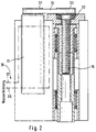
In Figur 2 ist eine parallele Anordnung des Antriebs 13 und der
Antriebsspindel 16 dargestellt, wobei gleiche Bauteile mit gleichen
Bezugszffiern versehen sind. Der Antrieb weist hierzu ein Antiebsritzel
31 auf, das in Form einer Riemenscheibe ausgebildet ist. Die parallel
zur Längsachse des Antriebs 13 und neben dem Antrieb 13
angeordnete Antriebsspindel 16 weist eine mittels Kugellager 32
gelagerte zweite Riemenscheibe 33 auf. Die Kraftübertragung von dem
Antrieb 13 auf die Anstriebsspindel 16 erfolgt über einen Riemen 34, der
in den Riemenscheiben 31 und 33 liegt. Der Riemen kann als Zahn-,
Keil- oder Poly-V-Riementrieb ausgebildet sein. Andere
Kupplungselemente 24 zwischen Antrieb und Antriebsspindel sind
einsetzbar. Bevorzugt ist dem Antrieb 13 ein Kühlsystem zugeordnet,
mittels dem ein höherer Motorwirkungsgrad erzielt wird. Das Kühlsystem
ist als Wasserkühlung ausgebildet, wobei über Eingang 36 Kühlwasser
zugeführt und über Ausgang 37 Kühlwasser abgeführt wird. Als
Kühlflüssigkeit oder -gas können selbstverständlich auch unterkühlte
Flüssigkeiten oder Öl, oder Luft eingesetzt werden.In Figure 2 is a parallel arrangement of the
In Figur 3 ist ein Programmprofil für den elektrischen Schweißantrieb 13 dargestellt, der einen Zyklus mit den Funktionen
- Zustellen
- Suchen
- Aufsetzen
- Anpressen - Schweißen 1. Zyklus
- Nachsetzen
- Nachhalten
- Zurückfahren
- To deliver
- Search
- Put on
- Press on - welding 1st cycle
- Reposition
- Follow up
- Drive back
positionieren über Lagerregelkreis (17, 19, 27, 28) auf Position Xl mit
max. Dynamik (MS). Der Wert Xl ist vorher aus den
Schweißprozeßwerten und den geometrischen Daten, die in der
Steuerung 15 abelegt sind, ermittelt.position via position control loop (17, 19, 27, 28) to position X l with max. Dynamics (M S ). The value X 1 is previously determined from the welding process values and the geometric data that are stored in the
Der Antrieb 13 schaltet automatisch auf Momentenregelkreis (18, 29,
30, 20) um und sucht das Werkstück 14.The
Der Antrieb 13 setzt mit einer leichten definierten Kraft auf dem
Werkstück 14 auf. Messung von dx/dt = o bzw. dw/dt = o ergibt die
Information über die Zielerreichung. In der Folge:The
Erhöhung der Aufpreßkraft auf F max. (M. max). Einschalten des Schweißstromes. Einleitung des Nachsetzvorganges.Increase the pressing force to F max. (M. max). Turn on the Welding current. Initiation of the repositioning process.
Zwei mögliche Verfahren:
- Kraft F bzw. Drehmoment M geregelt.
Messungen des Nachsetzweges Δx. - Lageregelung auf x mit M = M max. scharfe Regeleinstellung (PID ).
- Force F or torque M regulated.
Measurements of the repositioning path Δx. - Position control on x with M = M max. sharp control setting (PID).
Der Schweißstrom wird abgeschaltet bei:
- Erreichen eines max. zulässigen Δx oder
- nach einer definierten Zeit.
- Reaching a max. allowable Δx or
- after a defined time.
Dieser Position wird eine definierte Zeit nachgehalten (lagegeregelt).This position is held for a defined time (position-controlled).
Einleitung der Rückfahrt mittels eines Schalters. Lagegeregelte Positionierung auf x = xo.Initiation of the return journey using a switch. Position controlled Positioning on x = xo.
Claims (14)
einen regelbaren elektromotorischen Antrieb (13) der eine Antriebspindel (16) oder Zahnstange aufweist.Resistance pressure welding machine consisting of
a controllable electric motor drive (13) which has a drive spindle (16) or rack.
dadurch gekennzeichnet,
daß die Antriebsspindel (16) mit dem Schweißkopf (10) so verbunden ist, daß bei Betrieb des Antriebs (13) der Schweißkopf (10) in eine vorgegebene Position verfährt und in der vorgegebenen Position einen vorgegebenen Elektrodendruck auf das Werkstück (14) ausübt.Resistance pressure welding machine according to claim 1,
characterized,
that the drive spindle (16) is connected to the welding head (10) in such a way that, when the drive (13) is in operation, the welding head (10) moves into a predetermined position and exerts a predetermined electrode pressure on the workpiece (14) in the predetermined position.
dadurch gekennzeichnet,
daß der Antrieb (13) einen Weggeber (17) und/oder Drehmomentgeber (18) aufweist, die mit einem Vergleicher (19 bzw. 20) verbunden sind.Resistance pressure welding machine according to claim 1 or 2,
characterized,
that the drive (13) has a displacement sensor (17) and / or torque sensor (18) which are connected to a comparator (19 or 20).
dadurch gekennzeichnet,
daß die Vergleicher (19 bzw. 20) in der Steuerung (15) oder dem Antrieb (13) vorgesehen sind. Resistance pressure welding machine according to one of claims 1 to 3,
characterized,
that the comparators (19 and 20) are provided in the controller (15) or the drive (13).
dadurch gekennzeichnet,
daß die Vergleicher (19 bzw. 20) mit Sollwertgebern (21 bzw. 22) für die Eingabe von Weg-Sollwerten und Drehmoment-Sollwerten verbunden sind.Resistance pressure welding machine according to one of claims 1 to 4,
characterized,
that the comparators (19 and 20) are connected to setpoint transmitters (21 and 22) for the input of distance setpoints and torque setpoints.
dadurch gekennzeichnet,
daß die Sollwertgeber (21, 22) mit der Steuerung (15) verbunden sind.Resistance pressure welding machine according to one of claims 1 to 5,
characterized,
that the setpoint generator (21, 22) are connected to the controller (15).
dadurch gekennzeichnet,
daß der Antrieb (13) als Servomotor ausgebildet ist.Resistance pressure welding machine according to one of claims 1 to 6,
characterized,
that the drive (13) is designed as a servo motor.
dadurch gekennzeichnet,
daß der Antrieb (13) und die Antriebsspindel (16) parallel nebeneinander angeordnet und über ein Kupplungselement (24) miteinander verbunden sind.Resistance pressure welding machine according to one of claims 1 to 7,
characterized,
that the drive (13) and the drive spindle (16) are arranged in parallel next to one another and are connected to one another via a coupling element (24).
dadurch gekennzeichnet,
daß das Kupplungselement (24) ein Riemen (34) ist. Resistance pressure welding machine according to one of claims 1 to 8,
characterized,
that the coupling element (24) is a belt (34).
dadurch gekennzeichnet,
daß die Steuerung (15) eine Strom- und/oder Spannungs- und/oder Leistungs- und/oder Temperaturregelung aufweist.Resistance pressure welding machine according to one of claims 1 to 9,
characterized,
that the controller (15) has a current and / or voltage and / or power and / or temperature control.
dadurch gekennzeichnet,
daß mindestens einer der weiteren Parameter Kraft, Drehzahl und/oder Weg des elektrischen Antriebs (13) geregelt wird.Method for resistance pressure welding in which at least one of the parameters current, voltage, power and / or temperature is regulated,
characterized,
that at least one of the further parameters of force, speed and / or path of the electric drive (13) is regulated.
dadurch gekennzeichnet,
daß mindestens einer der Parameter Strom, Spannung, Leistung und/oder Temperatur und mindestens einer der Parameter Kraft, Drehzahl und/oder Weg von einer gemeinsamen Steuerung (15) geregelt werden.Method according to claim 12,
characterized,
that at least one of the parameters current, voltage, power and / or temperature and at least one of the parameters force, speed and / or path are regulated by a common controller (15).
dadurch gekennzeichnet,
daß durch Ansteuern des Antriebes (13) die Elektrode (11) bis kurz (x1) vor das Werkstück (14) gefahren wird und anschließend von der Weg - auf die Drehmomentregelung umgeschaltet wird.A method according to claim 12 or 13,
characterized,
that by driving the drive (13) the electrode (11) is moved shortly (x 1 ) in front of the workpiece (14) and then switched from the path to the torque control.
Applications Claiming Priority (2)
| Application Number | Priority Date | Filing Date | Title |
|---|---|---|---|
| DE19738647A DE19738647A1 (en) | 1997-09-04 | 1997-09-04 | Resistance pressure welding machine |
| DE19738647 | 1997-09-04 |
Publications (1)
| Publication Number | Publication Date |
|---|---|
| EP0901868A1 true EP0901868A1 (en) | 1999-03-17 |
Family
ID=7841165
Family Applications (1)
| Application Number | Title | Priority Date | Filing Date |
|---|---|---|---|
| EP98115704A Withdrawn EP0901868A1 (en) | 1997-09-04 | 1998-08-20 | Resistance spot welding machine |
Country Status (3)
| Country | Link |
|---|---|
| US (1) | US6064028A (en) |
| EP (1) | EP0901868A1 (en) |
| DE (1) | DE19738647A1 (en) |
Cited By (2)
| Publication number | Priority date | Publication date | Assignee | Title |
|---|---|---|---|---|
| CN105934305A (en) * | 2013-09-06 | 2016-09-07 | 美国阿玛达米亚基有限责任公司 | Weld head |
| WO2022058879A1 (en) * | 2020-09-17 | 2022-03-24 | Evg Entwicklungs- Und Verwertungsgesellschaft M.B.H. | Single-spot welding device |
Families Citing this family (24)
| Publication number | Priority date | Publication date | Assignee | Title |
|---|---|---|---|---|
| JP2783155B2 (en) * | 1994-04-20 | 1998-08-06 | 株式会社デンソー | Control method and device for resistance welding |
| US6337456B1 (en) * | 1998-12-16 | 2002-01-08 | Dengensha Manufacturing Company Limited | Welding machine and method for assembling same |
| DE19955691C2 (en) * | 1999-11-18 | 2002-11-28 | Kuka Schweissanlagen Gmbh | Method and device for resistance welding |
| DE10005963C2 (en) * | 2000-02-09 | 2003-04-17 | Reu Schweistechnik Gmbh | Spot welding control device |
| US6460007B1 (en) * | 2000-03-20 | 2002-10-01 | Daimlerchrysler Corporation | Method and apparatus for determination of resistance spot welded flange width |
| US6911615B2 (en) | 2000-11-02 | 2005-06-28 | Leander Reischmann | Welding head |
| DE10127112A1 (en) * | 2000-11-02 | 2002-08-01 | Leander Reischmann | welding head |
| US6455800B1 (en) * | 2001-01-04 | 2002-09-24 | Festo Corporation | Servo-pneumatic modular weld gun |
| DE10144286C1 (en) * | 2001-05-09 | 2003-01-02 | Cosytronic Computer System Ele | Process for judging the quality of a welding joint between two sheet metal parts during resistance welding comprises reducing the distance between the welding electrodes in a closing phase of the welding tongs |
| EP1291113A1 (en) * | 2001-09-11 | 2003-03-12 | Cosytronic Computer-System-Electronic GmbH | Welding gun and method of judging the weld quality |
| DE10144731B4 (en) * | 2001-09-11 | 2004-01-15 | Cosytronic Computer-System-Elektronic Gmbh | Welding gun and method for resistance welding with assessment of the quality of a welded joint |
| EP1472040B1 (en) * | 2002-02-05 | 2006-06-07 | SWAC Electronic GMBH | Drive device for welding tongs |
| DE20201734U1 (en) * | 2002-02-05 | 2003-07-24 | Swac Electronic Gmbh Zug | Drive unit for spot welding tongs used in automobile industry, is based on threaded spindle with motor-driven rotary nut |
| DE10258059B4 (en) * | 2002-12-11 | 2006-12-14 | Nimak-Automatisierte-Schweisstechnik Gmbh | Method for controlling a tool pressing force in joining devices |
| DE10360313B4 (en) * | 2003-12-18 | 2006-07-06 | PROMESS Gesellschaft für Montage- und Prüfsysteme mbH | welder |
| DE102004015689A1 (en) * | 2004-03-29 | 2005-10-27 | Cosytronic Computer-System-Elektronic Gmbh | Method for improving the quality of a spot weld |
| DE102004020438A1 (en) * | 2004-04-27 | 2005-11-24 | Daimlerchrysler Ag | Process to determine an electrode force in resistance welding as in motor vehicle robotic welding correlates movement of electrodes with that of the drive unit |
| DE102004048941A1 (en) * | 2004-10-07 | 2006-04-13 | Otto Bihler Handels-Beteiligungs-Gmbh | Welding machine, in particular mother welding device |
| DE102005021330B3 (en) * | 2005-05-04 | 2006-12-07 | Conntronic Prozess- Und Automatisierungstechnik Gmbh | Electric press welding process for multi-part workpieces involves placing parts in transportable workpiece holder outside welding machine and inserting tool plates |
| DE102005056808A1 (en) * | 2005-11-29 | 2007-05-31 | Volkswagen Ag | Single-electrode spot-welding procedure suitable for car bodywork, raises mechanical pressure to maximum, then reduces it whilst increasing welding current |
| DE102006006400A1 (en) * | 2006-02-11 | 2007-09-06 | Zf Friedrichshafen Ag | Method for welding a floor to a cylinder of a vibration damper |
| DE102012000462A1 (en) | 2012-01-13 | 2013-07-18 | Erdogan Karakas | Resistance welding of workpieces in which force applied to electrode is controlled and/or regulated, comprises changing, controlling, regulating and/or modulating force applied to electrodes before and/or after welding process |
| DE102014217079A1 (en) * | 2014-08-27 | 2016-03-03 | Otto Bihler Handels-Beteiligungs-Gmbh | Resistance welding machine |
| KR102176292B1 (en) * | 2020-07-01 | 2020-11-09 | 주식회사 에스디앤티 | Spot welder that can move position easily |
Citations (6)
| Publication number | Priority date | Publication date | Assignee | Title |
|---|---|---|---|---|
| FR2585976A1 (en) * | 1985-08-09 | 1987-02-13 | Aro | Digitally-controlled resistance welding machine with a screw and nut system or the like |
| WO1990014920A1 (en) * | 1989-05-30 | 1990-12-13 | Ferdinand Schwob | Device for actuating the welding electrode or tongs of resistance welding machines |
| JPH06155040A (en) * | 1992-11-16 | 1994-06-03 | Nissan Motor Co Ltd | Welding equipment |
| US5321225A (en) * | 1991-04-08 | 1994-06-14 | Aro | Installation for controlling tooling including a clamp for performing a determined operation on workpieces, relative displacement of the clamp and said workpieces being controlled by an automatic positioning system |
| US5340960A (en) * | 1991-10-11 | 1994-08-23 | Kawasaki Jukogyo Kabushiki Kaisha | Control apparatus for spot welding robot |
| FR2728820A1 (en) * | 1994-12-30 | 1996-07-05 | Renault | RESISTANCE WELDING DEVICE WITH EFFORT CONTROL |
Family Cites Families (8)
| Publication number | Priority date | Publication date | Assignee | Title |
|---|---|---|---|---|
| DE3711771A1 (en) * | 1987-04-08 | 1988-10-27 | Sts Systemtechnik Und Software | Method and arrangement for process control in spot welding |
| US5225647A (en) * | 1991-11-04 | 1993-07-06 | Unitek Equipment Inc. | Motorized weld head |
| US5386092A (en) * | 1991-11-04 | 1995-01-31 | Unitek Equipment Inc. | Fast response weld head |
| JP3114440B2 (en) * | 1993-07-22 | 2000-12-04 | 日産自動車株式会社 | Spot welding equipment |
| DE69406614T2 (en) * | 1993-08-25 | 1998-06-25 | Toyota Motor Co Ltd | Control method for spot welding, and device that uses a controlled welding gun |
| FR2709994B1 (en) * | 1993-09-13 | 1995-11-24 | Aro | Method of force control on resistance welding tongs or the like; resistance welding machine applying this process. |
| JPH07232282A (en) * | 1994-02-25 | 1995-09-05 | Obara Kk | Controller of c-type welding gun |
| US5898285A (en) * | 1997-03-11 | 1999-04-27 | Honda Giken Kogyo Kabushiki Kaisha | Method of teaching welding robot |
-
1997
- 1997-09-04 DE DE19738647A patent/DE19738647A1/en not_active Withdrawn
-
1998
- 1998-08-20 EP EP98115704A patent/EP0901868A1/en not_active Withdrawn
- 1998-09-03 US US09/146,594 patent/US6064028A/en not_active Expired - Lifetime
Patent Citations (6)
| Publication number | Priority date | Publication date | Assignee | Title |
|---|---|---|---|---|
| FR2585976A1 (en) * | 1985-08-09 | 1987-02-13 | Aro | Digitally-controlled resistance welding machine with a screw and nut system or the like |
| WO1990014920A1 (en) * | 1989-05-30 | 1990-12-13 | Ferdinand Schwob | Device for actuating the welding electrode or tongs of resistance welding machines |
| US5321225A (en) * | 1991-04-08 | 1994-06-14 | Aro | Installation for controlling tooling including a clamp for performing a determined operation on workpieces, relative displacement of the clamp and said workpieces being controlled by an automatic positioning system |
| US5340960A (en) * | 1991-10-11 | 1994-08-23 | Kawasaki Jukogyo Kabushiki Kaisha | Control apparatus for spot welding robot |
| JPH06155040A (en) * | 1992-11-16 | 1994-06-03 | Nissan Motor Co Ltd | Welding equipment |
| FR2728820A1 (en) * | 1994-12-30 | 1996-07-05 | Renault | RESISTANCE WELDING DEVICE WITH EFFORT CONTROL |
Non-Patent Citations (1)
| Title |
|---|
| PATENT ABSTRACTS OF JAPAN vol. 018, no. 472 (M - 1667) 2 September 1994 (1994-09-02) * |
Cited By (2)
| Publication number | Priority date | Publication date | Assignee | Title |
|---|---|---|---|---|
| CN105934305A (en) * | 2013-09-06 | 2016-09-07 | 美国阿玛达米亚基有限责任公司 | Weld head |
| WO2022058879A1 (en) * | 2020-09-17 | 2022-03-24 | Evg Entwicklungs- Und Verwertungsgesellschaft M.B.H. | Single-spot welding device |
Also Published As
| Publication number | Publication date |
|---|---|
| DE19738647A1 (en) | 1999-03-25 |
| US6064028A (en) | 2000-05-16 |
Similar Documents
| Publication | Publication Date | Title |
|---|---|---|
| EP0901868A1 (en) | Resistance spot welding machine | |
| DE69728714T2 (en) | Method and device for spot welding | |
| EP1414610B1 (en) | Resistance welding device and control method | |
| DE102011108896A1 (en) | Apparatus for detecting machining information in a machining apparatus that supplies power or material at a machining position | |
| EP1125672A2 (en) | Method and apparatus for joining workpieces by using a beam of energy, especially a laserbeam | |
| EP3049210B1 (en) | Pressure welding device and pressure welding method using an advancing drive designed as an electro-hydraulic direct drive | |
| DE2701413C2 (en) | Control device for the DC motor of the feed drive of a table or the like. on machine tools | |
| EP2091699B1 (en) | Method and device for fine-positioning a tool having a handling device | |
| DE3710688C2 (en) | Robotic tool | |
| DE2754261C2 (en) | Device for electrical discharge machining of a workpiece | |
| DE3045493A1 (en) | SPARK EDM CUTTING MACHINE | |
| DE3301170A1 (en) | PROGRAM-CONTROLLED EDGE GRINDING MACHINE FOR GLASS DISC WITH A PROGRAM-CONTROLLED ROTATING GRINDING HEAD | |
| EP0997801A2 (en) | Linear drive means for machining tools | |
| EP0120198A1 (en) | Method of operating an industrial robot in robot kinematic foreign coordinates | |
| DE10249071B3 (en) | Linear drive for material feed on machine tools | |
| DE3837526C2 (en) | ||
| DE3638698C2 (en) | Device for linear movement of a machine part of a numerically controlled machine tool | |
| DD275632A1 (en) | DEVICE FOR AUTOMATICALLY POSITIONING A TOOTH LEFT OF A GEAR WHEEL | |
| DE3300734A1 (en) | Feed drive for a multi-spindle machine | |
| DE1463460B2 (en) | Arrangement for numerical path control, especially for machine tools | |
| US3548144A (en) | Method and apparatus for controlling the platen of a flash welder | |
| DE2306291A1 (en) | DEVICE FOR POSITIONING TOOLS IN MACHINES FOR CUTTING AND SCORING CORRUGATED BOARD FOR CARDBOARD MANUFACTURING | |
| WO1999065800A2 (en) | Method and device for processing components | |
| DE3418365A1 (en) | Control system for a direct-current work-spindle drive | |
| DE2331767A1 (en) | CONTROL DEVICE FOR SLIDES ON MACHINE TOOLS |
Legal Events
| Date | Code | Title | Description |
|---|---|---|---|
| PUAI | Public reference made under article 153(3) epc to a published international application that has entered the european phase |
Free format text: ORIGINAL CODE: 0009012 |
|
| AK | Designated contracting states |
Kind code of ref document: A1 Designated state(s): AT BE CH DE FR GB IT LI NL |
|
| AX | Request for extension of the european patent |
Free format text: AL;LT;LV;MK;RO;SI |
|
| 17P | Request for examination filed |
Effective date: 19990917 |
|
| AKX | Designation fees paid |
Free format text: AT BE CH DE FR GB IT LI NL |
|
| 17Q | First examination report despatched |
Effective date: 20010822 |
|
| RAP1 | Party data changed (applicant data changed or rights of an application transferred) |
Owner name: PECO WELDING SYSTEMS GMBH |
|
| STAA | Information on the status of an ep patent application or granted ep patent |
Free format text: STATUS: THE APPLICATION HAS BEEN WITHDRAWN |
|
| 18W | Application withdrawn |
Withdrawal date: 20020731 |