EP0901822A2 - Entnahmegefäss Anordnung - Google Patents
Entnahmegefäss Anordnung Download PDFInfo
- Publication number
- EP0901822A2 EP0901822A2 EP98115775A EP98115775A EP0901822A2 EP 0901822 A2 EP0901822 A2 EP 0901822A2 EP 98115775 A EP98115775 A EP 98115775A EP 98115775 A EP98115775 A EP 98115775A EP 0901822 A2 EP0901822 A2 EP 0901822A2
- Authority
- EP
- European Patent Office
- Prior art keywords
- container
- assembly
- bottom portion
- top portion
- collection
- Prior art date
- Legal status (The legal status is an assumption and is not a legal conclusion. Google has not performed a legal analysis and makes no representation as to the accuracy of the status listed.)
- Withdrawn
Links
Images


Classifications
-
- B—PERFORMING OPERATIONS; TRANSPORTING
- B01—PHYSICAL OR CHEMICAL PROCESSES OR APPARATUS IN GENERAL
- B01L—CHEMICAL OR PHYSICAL LABORATORY APPARATUS FOR GENERAL USE
- B01L3/00—Containers or dishes for laboratory use, e.g. laboratory glassware; Droppers
- B01L3/50—Containers for the purpose of retaining a material to be analysed, e.g. test tubes
- B01L3/508—Containers for the purpose of retaining a material to be analysed, e.g. test tubes rigid containers not provided for above
- B01L3/5082—Test tubes per se
Definitions
- This invention relates to a specimen collection container assembly and more particularly to a collection container for collecting biological fluid specimens where a small quantity of fluid may be collected and retained in the container while maintaining a container size sufficient to be easily accommodated and/or compatible with standard clinical equipment and instrumentation.
- Blood samples and other biological fluid specimens are routinely taken and analyzed in hospital and clinical situations for various medical purposes. Collection, handling and testing of these samples typically requires the use of various medical testing instruments. As the blood and fluid specimens are usually collected in a standard sized collection tube, the medical instruments used to test the samples are designed to accommodate these standard sized collection tubes.
- Conventional blood collection tubes used in most clinical situations are elongated cylindrical containers having one end closed by a semi-spherical or rounded portion and an opposed open end. The open end may be sealed by a resilient cap or stopper.
- the tube defines a collection interior which collects and holds the blood sample.
- the most common size of these blood collection tubes are designed to accommodate approximately 10 ml of blood or other biological fluid samples.
- Illustrative of such blood collection tubes is the VACUTAINER® brand blood collection tube sold by Becton, Dickinson and Company, 1 Becton Drive, Franklin Lakes, NJ (registered trademark of Becton, Dickinson and Company).
- a phlebotomist or other medical technician typically obtains a specimen of the patient's blood in the tube by techniques well known in the art.
- the tube is then appropriately labeled and transferred from the site of collection to a laboratory or other location where the contents of the tube are analyzed.
- the tube may be supported by various medical instruments.
- the plasma or serum derived therefrom is processed and analyzed either manually, semiautomatically or automatically. In some cases, the specimen must first be dispensed from the collection tube to a sample test tube or cuvette.
- specimen containers such as those incorporating a "false bottom” have been proposed to achieve decreased volume capacity in conjunction with standard external dimensions.
- these various specimen containers are not compatible with standard clinical equipment and instrumentation due to their design.
- these specimen containers have false bottoms with a generally fiat, planar bottom end and a circular shaped opening.
- specimen containers include partial-draw tubes which have standard external dimensions with partial evacuation so that blood fills only a portion of the internal volume.
- partial-draw tubes exhibit a reduction in the draw rate of a sample which reduces the collection efficiency of such tubes.
- partial-draw tubes may result in an inconsistent fill volume which may alter test results.
- it is difficult to determine the accurate sample quantities with such partial-draw tubes because the slow rate of sample draw is not consistently measurable.
- the present invention is a collection assembly comprising a first container and a second container.
- the first container preferably comprises an open top portion, a bottom portion and a sidewall extending from the open top portion to the bottom portion.
- the bottom portion comprises a closed bottom end or true bottom and an annular skirt extending from the closed bottom end to a stop end at a lower bottom portion.
- the assembly further comprises a second container that may be secured and unsecured to the lower bottom portion of the container.
- the second container comprises a top portion, a bottom portion, a sidewall extending from the top portion to the bottom portion and an open end associated with the top portion having an integral connector.
- the integral connector has an inner surface, an outer surface, and ribs associated with the outer surface of the connector.
- the bottom portion is fully rounded or substantially spherical in shape.
- the integral connector fits or mates with the lower bottom portion of the annual skirt of the first container.
- the second container is removably secured to the first container whereby the integral connector is inserted into the annular skirt of the first container by force or friction fit. Thereby, the second container provides the assembly with a false bottom end that is rounded.
- the second container may be the same or different material than the first container.
- the second container is removably unsecured from the first container whereby the user slightly twists the first container and the second container in opposite rotating directions thereby releasing the integral connector from the annual skirt and removing the second container from the first container.
- the annular skirt of the container provides a false bottom effect to the assembly and the second container provides a means for allowing the first container to be modified so as to be compatible with standard clinical equipment and instrumentation.
- the true bottom may be the same or different material than the first container and may be integral with the container or may be a discrete member. Additionally, the true bottom may be arcuate in shape to provide an internal volume for specimen collection having at least a partially rounded true bottom portion, or may be conical in shape.
- the assembly may further comprise a closure such as a cap or a stopper at the open end of the first container.
- the external dimensions of the assembly which includes the first container and the second container are substantially the same as a standard-sized or full draw blood collection container assembly.
- the assembly of the present invention can be either evacuated or non-evacuated.
- the assembly is made from polyethylene terephthalate, polypropylene, polyethylene, polyethylene napthalate polyvinyl chloride or copolymers thereof.
- An advantage of the assembly of the present invention is that it provides a full-draw blood collection container assembly having a reduced internal volume but with external dimensions about the same as a standard-sized blood collection container assembly.
- a further advantage of the assembly of the present invention is that it provides a specimen collection container which is universally compatible with various clinical equipment and instrumentation.
- the assembly of the present invention may be easily handled by equipment configured to handle standard-sized blood collection tubes having standard external dimensions.
- the assembly of the present invention provides a blood collection container having full draw external dimensions but with a reduced internal volume as compared to standard-sized full draw blood collection.
- Standard-sized full draw blood collection containers have an outer diameter of about 13 to about 16 millimetres, a length of about 75 to about 100 millimeters and an internal volume of about 6 to about 10 milliliters.
- the assembly of the present invention therefore addresses the need for a full-draw low-volume blood collection container assembly that presents the external dimensions of a standard-sized blood collection tube.
- the assembly of the present invention may be used to reliably collect small samples of blood or biological fluids and to maintain the integrity of the samples during storage and transport as compared to using standard-sized blood collection tubes.
- the assembly of the present invention can also be accommodated by standard-sized blood collection, transportation, storage, and diagnostic equipment.
- the assembly of the present invention provides a rounded bottom configuration that is substantially the same as a standard-sized blood collection tube with a fully rounded bottom.
- the assembly of the present invention is also compatible with existing instrumentation, labels, and bar code readers and obviates the need for new instrumentation and handling devices or procedures that would be required for smaller or varying sized tubes or tubes with flat planar bottoms.
- FIGS. 1 and 2 show a false bottom specimen container 10 of the prior art, having a sidewall 12 having an outer surface 14 and an inner surface 16 .
- Cylindrical sidewall 12 extends from an upper portion 18 to a lower portion 20.
- Upper portion 18 includes an open end 22 and a rim 24 .
- Lower portion 20 comprises a closed bottom end 26 .
- An annular skirt 28 extends from lower portion 20 and outer surface 14 to a flat planar bottom end 30 to define an open false bottom area 36 .
- Interior volume 34 extends between rim 2 4 and dosed bottom end 26 .
- FIGS. 3 and 4 show the preferred embodiment of the present invention, assembly 50 .
- Assembly 50 comprises a first specimen container 52 , having a cylindrical sidewall 62 having an outer surface 64 and an inner surface 66 .
- Sidewall 62 extends from an upper portion 68 to a lower portion 70 .
- Upper portion 68 includes an open end 72 and an integral neck 74 .
- Integral neck 74 has a first cylindrical sidewall 76 that extends from a rim 77 to a second cylindrical sidewall 78 .
- Second cylindrical sidewall 78 has an external diameter less than the external diameter of first cylindrical sidewall 76 .
- Second cylindrical sidewall 78 tapers inwardly towards cylindrical sidewall 62 , wherein the external diameter of sidewall 62 is less than the external diameter of second cylindrical sidewall 78 .
- First cylindrical sidewall 76 includes an inner surface 80 an outer surface 82 and threads 84 located on outer surface 82 for cooperating with threads on a closure.
- Lower portion 70 of assembly 50 comprises a closed bottom end or true bottom 86 .
- An annular skirt 88 having an outer surface 90 and an inner surface 92 , extends from lower portion 70 and outer surface 64 to a bottom end or false bottom end 94 to define an open false bottom area 96 and planar rim surface 98 .
- An interior volume 99 extends between rim 77 and closed bottom end 76 .
- Closed bottom end 76 may be positioned at any point below rim 77 thus providing a variable interior volume 99.
- Closed bottom end 76 may be generally fiat or planar in shape to provide a flat bottom surface for interior volume 99 .
- closed bottom end 76 may be arcuate in shape to provide at least a partially rounded bottom surface for interior volume 99 .
- Most preferably, closed bottom end is generally conical in shape to provide a conical, pointed bottom surface for interior volume 99 .
- dosed bottom end 76 may be integral with sidewall 62 or may be a discrete member.
- closed bottom end 76 is integrally formed with sidewall 62 .
- second container 100 includes a top portion 102, a bottom portion 104 , a cylindrical sidewall 106 extending from the top portion to the bottom portion, an open end 108 associated with top portion 102 and an integral connector 110 extending from top portion 102.
- Integral connector 110 extends between a top portion 112 and a bottom portion 114 having a cylindrical sidewall 116 that includes an inner surface 118 and an outer surface 120.
- a plurality of ribs 122 are associated on outer surface 120.
- Cylindrical sidewall 116 has an external diameter less than the external diameter of cylindrical sidewall 106 .
- the bottom portion of the integral connector is connected to top portion 102 by a flat shoulder surface 124 .
- Bottom portion 104 is fully rounded or substantially semi-spherical in shape.
- assembly 50 has an outer diameter A of about 16 millimeters, a length B of about 75 millimeters, as measured from rim 74 to bottom portion 104 of second container 100 , and an interior volume 94 of about 1 to 3 milliliters. It is within the purview of this invention that assembly 50 may have an outer diameter of about 13 to about 16 millimeters, a length of about 75 to about 100 millimeters and an interior volume of about 1 to about 3 millilitres.
- Annular skirt 88 provides a means for allowing the container to be placed upright on a flat surface, as well as providing a meads for converting the assembly with the second container to substantially the same external dimensions as a standard-sized blood collection tube.
- second container 100 is readily compatible with open false bottom area 96 .
- Open false bottom area 96 receives integral connector 110 of second container 100 whereby inner surface 92 of annular skirt 88 and ribs 122 of integral connector 110 provide an interference fit and flat shoulder surface 124 meets with planar rim surface 98 .
- the second container may be removed from the first container whereby the user slightly twists the first container and the second container in opposite directions thereby removing the second container from the first container.
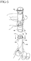
- FIG. 6 includes many components which are substantially identical to the components of FIGS. 3-4. Accordingly, similar components performing similar functions will be numbered identically to those components of FIGS. 3-4, except that a suffix "a" will be used to identify the similar components in FIG. 6.
- a further embodiment of the invention is assembly 150 which includes a closure 160.
- FIG. 6 may be evacuated or non-evacuated.
- interior volume 99a is typically maintained at a lower-than-atmospheric internal pressure so that when a blood collection probe penetrates through the closure placing interior volume 99a in communication with the circulatory system of a patient, the lower-than-atmospheric pressure of interior volume 99a will draw blood from the patient into the tube.
- Assembly 150 may be described as a full-draw blood collection tube because the internal pressure of interior volume 99a is low enough to draw a volume of blood substantially equal to the volume of interior volume 99a.
Landscapes
- Health & Medical Sciences (AREA)
- Chemical & Material Sciences (AREA)
- Analytical Chemistry (AREA)
- General Health & Medical Sciences (AREA)
- Hematology (AREA)
- Clinical Laboratory Science (AREA)
- Chemical Kinetics & Catalysis (AREA)
- Measurement Of The Respiration, Hearing Ability, Form, And Blood Characteristics Of Living Organisms (AREA)
- Sampling And Sample Adjustment (AREA)
- Automatic Analysis And Handling Materials Therefor (AREA)
Applications Claiming Priority (2)
| Application Number | Priority Date | Filing Date | Title |
|---|---|---|---|
| US928249 | 1992-08-10 | ||
| US92824997A | 1997-09-12 | 1997-09-12 |
Publications (2)
| Publication Number | Publication Date |
|---|---|
| EP0901822A2 true EP0901822A2 (de) | 1999-03-17 |
| EP0901822A3 EP0901822A3 (de) | 2000-01-12 |
Family
ID=25455956
Family Applications (1)
| Application Number | Title | Priority Date | Filing Date |
|---|---|---|---|
| EP98115775A Withdrawn EP0901822A3 (de) | 1997-09-12 | 1998-08-21 | Entnahmegefäss Anordnung |
Country Status (4)
| Country | Link |
|---|---|
| EP (1) | EP0901822A3 (de) |
| JP (1) | JPH11151214A (de) |
| AU (1) | AU8301698A (de) |
| CA (1) | CA2242940A1 (de) |
Cited By (2)
| Publication number | Priority date | Publication date | Assignee | Title |
|---|---|---|---|---|
| US8747381B2 (en) | 2007-07-12 | 2014-06-10 | Sysmex Corporation | Specimen container |
| US10464060B2 (en) * | 2011-11-10 | 2019-11-05 | BioFare Diagnostics, LLC | Loading vials |
Citations (5)
| Publication number | Priority date | Publication date | Assignee | Title |
|---|---|---|---|---|
| US3615222A (en) * | 1968-09-04 | 1971-10-26 | New England Nuclear Corp | Method and apparatus for measuring the amount of a component in a biological fluid |
| US5264184A (en) * | 1991-03-19 | 1993-11-23 | Minnesota Mining And Manufacturing Company | Device and a method for separating liquid samples |
| US5325980A (en) * | 1992-08-20 | 1994-07-05 | Grimm Michael C | Locking vial |
| EP0636343A1 (de) * | 1993-05-12 | 1995-02-01 | Becton, Dickinson and Company | Abnahmeröhrchen |
| US5533518A (en) * | 1994-04-22 | 1996-07-09 | Becton, Dickinson And Company | Blood collection assembly including mechanical phase separating insert |
-
1998
- 1998-07-13 CA CA002242940A patent/CA2242940A1/en not_active Abandoned
- 1998-08-21 EP EP98115775A patent/EP0901822A3/de not_active Withdrawn
- 1998-08-31 AU AU83016/98A patent/AU8301698A/en not_active Abandoned
- 1998-09-14 JP JP10260576A patent/JPH11151214A/ja active Pending
Patent Citations (5)
| Publication number | Priority date | Publication date | Assignee | Title |
|---|---|---|---|---|
| US3615222A (en) * | 1968-09-04 | 1971-10-26 | New England Nuclear Corp | Method and apparatus for measuring the amount of a component in a biological fluid |
| US5264184A (en) * | 1991-03-19 | 1993-11-23 | Minnesota Mining And Manufacturing Company | Device and a method for separating liquid samples |
| US5325980A (en) * | 1992-08-20 | 1994-07-05 | Grimm Michael C | Locking vial |
| EP0636343A1 (de) * | 1993-05-12 | 1995-02-01 | Becton, Dickinson and Company | Abnahmeröhrchen |
| US5533518A (en) * | 1994-04-22 | 1996-07-09 | Becton, Dickinson And Company | Blood collection assembly including mechanical phase separating insert |
Cited By (4)
| Publication number | Priority date | Publication date | Assignee | Title |
|---|---|---|---|---|
| US8747381B2 (en) | 2007-07-12 | 2014-06-10 | Sysmex Corporation | Specimen container |
| EP2172778B1 (de) * | 2007-07-12 | 2017-12-27 | Sysmex Corporation | Probenbehälter |
| US10464060B2 (en) * | 2011-11-10 | 2019-11-05 | BioFare Diagnostics, LLC | Loading vials |
| US10913060B2 (en) | 2011-11-10 | 2021-02-09 | Biofire Diagnostics, Llc | Loading vials |
Also Published As
| Publication number | Publication date |
|---|---|
| JPH11151214A (ja) | 1999-06-08 |
| AU8301698A (en) | 1999-03-25 |
| EP0901822A3 (de) | 2000-01-12 |
| CA2242940A1 (en) | 1999-03-12 |
Similar Documents
| Publication | Publication Date | Title |
|---|---|---|
| US5955032A (en) | Collection container assembly | |
| US5938621A (en) | Collection container assembly | |
| JP5318746B2 (ja) | 採集容器アッセンブリ | |
| EP0901821B1 (de) | Entnahmegefäss Anordnung | |
| EP0901817B1 (de) | Entnahmegefäss Anordnung | |
| EP0901818B1 (de) | Sammelgefäss | |
| US5975343A (en) | Collection container assembly | |
| EP0901822A2 (de) | Entnahmegefäss Anordnung |
Legal Events
| Date | Code | Title | Description |
|---|---|---|---|
| PUAI | Public reference made under article 153(3) epc to a published international application that has entered the european phase |
Free format text: ORIGINAL CODE: 0009012 |
|
| AK | Designated contracting states |
Kind code of ref document: A2 Designated state(s): DE FR GB IT |
|
| AX | Request for extension of the european patent |
Free format text: AL;LT;LV;MK;RO;SI |
|
| PUAL | Search report despatched |
Free format text: ORIGINAL CODE: 0009013 |
|
| AK | Designated contracting states |
Kind code of ref document: A3 Designated state(s): AT BE CH CY DE DK ES FI FR GB GR IE IT LI LU MC NL PT SE |
|
| AX | Request for extension of the european patent |
Free format text: AL;LT;LV;MK;RO;SI |
|
| 17P | Request for examination filed |
Effective date: 20000623 |
|
| AKX | Designation fees paid |
Free format text: DE FR GB IT |
|
| 17Q | First examination report despatched |
Effective date: 20030923 |
|
| STAA | Information on the status of an ep patent application or granted ep patent |
Free format text: STATUS: THE APPLICATION IS DEEMED TO BE WITHDRAWN |
|
| 18D | Application deemed to be withdrawn |
Effective date: 20040204 |