EP0901774B1 - Device for assisting parturition of animals - Google Patents
Device for assisting parturition of animals Download PDFInfo
- Publication number
- EP0901774B1 EP0901774B1 EP98112114A EP98112114A EP0901774B1 EP 0901774 B1 EP0901774 B1 EP 0901774B1 EP 98112114 A EP98112114 A EP 98112114A EP 98112114 A EP98112114 A EP 98112114A EP 0901774 B1 EP0901774 B1 EP 0901774B1
- Authority
- EP
- European Patent Office
- Prior art keywords
- lever
- sleeve
- sleeve part
- rod
- clamping
- Prior art date
- Legal status (The legal status is an assumption and is not a legal conclusion. Google has not performed a legal analysis and makes no representation as to the accuracy of the status listed.)
- Expired - Lifetime
Links
- 241001465754 Metazoa Species 0.000 title claims description 15
- 230000032696 parturition Effects 0.000 title 1
- 230000000994 depressogenic effect Effects 0.000 claims description 3
- 210000002414 leg Anatomy 0.000 description 29
- 241000283690 Bos taurus Species 0.000 description 8
- 230000015572 biosynthetic process Effects 0.000 description 1
- 230000000903 blocking effect Effects 0.000 description 1
- 230000006835 compression Effects 0.000 description 1
- 238000007906 compression Methods 0.000 description 1
- 238000011109 contamination Methods 0.000 description 1
- 230000001419 dependent effect Effects 0.000 description 1
- 230000000881 depressing effect Effects 0.000 description 1
- 230000000694 effects Effects 0.000 description 1
- 230000008774 maternal effect Effects 0.000 description 1
- 210000000689 upper leg Anatomy 0.000 description 1
Images

Classifications
-
- A—HUMAN NECESSITIES
- A61—MEDICAL OR VETERINARY SCIENCE; HYGIENE
- A61D—VETERINARY INSTRUMENTS, IMPLEMENTS, TOOLS, OR METHODS
- A61D1/00—Surgical instruments for veterinary use
- A61D1/08—Veterinary obstetrical instruments or devices
Definitions
- the invention relates to a device for cattle obstetrics, with a neck support that can be supported against the body of a mother animal, which picks up a pole with two arranged on the pole, alternately displaceable and lockable sleeve-shaped Split, with each sleeve-shaped part one off the bar enforced clamping ring, which means spring force in the sense one defining the sleeve-shaped part and the rod Is clamped, with at least two holding devices, on at least one of the two sleeve-shaped Parts are attached and in the direction of tension with the holding devices connectable leg slings for the Allow young animals, as well as in one of the sleeve-shaped parts a clamping lever is pivotally mounted at a distance from an intermediate link pivotally receives its pivot axis and the intermediate link also in the other sleeve-shaped part is pivotally mounted, with a device for releasing the fixed sleeve-shaped parts, one in one of the sleeve-
- Such a device for cattle obstetrics is from DE 44 41 795 C1 known.
- the clamping ring prevents the one sleeve-shaped Part in its clamping position that the clamping lever in its fully swiveled-in position can be transferred, because the approach of the clamping lever the end face of this clamping ring contacted.
- one sleeve-shaped part is one by hand plunger that can be actuated against spring force, the end face in contact with the clamping ring of a sleeve-shaped Part can be brought and this from its clamped position moves, the clamping ring also from the path of movement of the Approach lever attached approach so that this in his fully pivoted position can be transferred and so that the other approach of the pivot lever also take effect can of the clamping ring of the other sleeve-shaped part moved to its clamped position. So that the two are sleeve-shaped Parts released with respect to the rod and can be moved in the direction of the Neck support or the mother animal slip, so that the tension the leg loops for the young animal are reduced.
- the trigger element designed as a plunger be operated in the immediate vicinity of the tensioning lever.
- the formation of the trigger element as a plunger also makes it required to exert significant triggering forces when the in the holding devices are attached to the leg slings.
- the device has a sleeve-shaped one Part assigned clamping ring the function of the stop for the Approach on the tension lever. For example, as a result of Contamination the provision of this clamping disc under Spring force is not perfect, so is the stop function this clamping ring for the attachment to the clamping lever is not guaranteed.
- EP 0 608 790 A1 describes a device for cattle obstetrics known in which a device for solving the two set sleeve-shaped parts is provided as a trigger element a pivotally mounted in a sleeve-shaped part Has release lever.
- a device for solving the two set sleeve-shaped parts is provided as a trigger element a pivotally mounted in a sleeve-shaped part Has release lever.
- the task is solved with a device for cattle obstetrics type mentioned in that the trigger element as Trigger lever pivotally mounted in a sleeve-shaped part is formed, the trigger lever having a shoulder, the in a first position of the release lever in the swivel path one end of the tension lever protrudes and a complete one Swiveling of the tensioning lever prevented, as well as the release lever when transferring to a second position in which he has the clamping ring one of the sleeve-shaped parts moved out of the clamping position, from the swivel path of the approach of the tensioning lever to it is completely swung in.
- the trigger element as Trigger lever pivotally mounted in a sleeve-shaped part is formed, the trigger lever having a shoulder, the in a first position of the release lever in the swivel path one end of the tension lever protrudes and a complete one Swiveling of the tensioning lever prevented, as well as the release lever when transferring to a second position in which
- the Approach of the release lever in its inactive position Block the tension lever by the approach of the release lever protrudes into the swivel path of the approach of the tensioning lever.
- the Clamping lever or its approach therefore contacts with this Condition of the clamping ring is not.
- the limitation of the swivel path the clamping lever depends only on the position of the release element or its approach. The clamping is released the clamping ring assigned to the trigger element immediately through the trigger element.
- the approach of the trigger element is pivoted out of the path of movement of the clamping lever, with what this now when moving the released sleeve-shaped Part fully swiveled on the rod and this the other approach of the tensioning lever the other's clamping ring sleeve-shaped part transferred to the unclamped position.
- the triggering element is not actuated in one rectilinear movement, but by means of a swivel movement.
- a special design provides that the release lever as Angle lever is formed, the trigger lever in the angular range its leg pivotable in the tension lever facing Area of a sleeve-shaped part is mounted.
- the leg that serves to contact the clamping ring in stored in its immediate vicinity, essentially parallel to this.
- the approach of the release lever is preferred in the area the pivot axis of the release lever.
- each Leg part is arranged on the side of the rod.
- the forces can be symmetrical to the central longitudinal axis of the rod to release the clamping of the clamping ring in the sleeve-shaped Part, which has the trigger element, are applied.
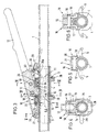
- FIGS. 1 and 2 points the device shown for the areas essential to the invention for cattle obstetrics a hollow tube designed as smooth on the outside Bar 1 on.
- the dash-dotted line 2 illustrates the Position of a not shown, against the body of the Maternal supportable neck support, in which the rod with one end is insertable. The end facing away from the mother animal the rod is also not clearly illustrated and is useful a handle on. Between the neck support and the with the other end of the rod connected handle are on the Rod 1 two alternately slidable and lockable, sleeve-shaped parts 3 and 4 arranged.
- the mother animal facing sleeve-shaped part 3 is arranged with two diametrically Holding devices 5 and 6 and the other sleeve-shaped Part 4 provided with a holding device 38, which as on the open hooks are formed on the side facing away from the mother animal.
- a holding device 38 which as on the open hooks are formed on the side facing away from the mother animal.
- the attack directions of the in the holding devices 5 and 6 are attached leg slings in the representation of Figure 2 with dash-dotted lines illustrated.
- the sleeve-shaped parts 3 and 4 are in means to be described in more detail below Clamping rings 8 and 9 can be fixed, which passes through the rod 1 become.
- each Clamping ring 8 or 9 is slightly larger than the outer diameter the rod 1, so that the sleeve-shaped parts 3 and 4, with clamping rings 8 and 9 oriented perpendicular to the rod 1, free and largely free of play on the rod 1 in its Can slide in the longitudinal direction, however, an inclined position Clamping rings 8 and 9 from this shown in Figures 1 and 2 Position for fixing the sleeve-shaped parts 3 and 4 relative leads to rod 1.
- the sleeve-shaped part 4 a clamping lever 12 pivotally connected, a bearing axis 13 in two bearing legs 14 and 15 of the sleeve-shaped part 4 is held and a through hole interspersed in the clamping lever 12.
- the tension lever 12 is an intermediate member 16 with the tension lever 12 connected, the intermediate member 16 also two Bearing legs 17 and 18.
- a bearing axis 19 in the two bearing legs 17th and 18 held and penetrated a through hole in Clamping lever 12.
- In the area of the sleeve-shaped part 3 is one Bearing axis 20 arranged in the two bearing legs 17th and 18 of the intermediate member 16 is held and a through hole an approach 21 of the sleeve-shaped part 3 penetrates.
- each sleeve-shaped part 3 or 4 has on the mother animal facing away from a blind hole 22 for sliding Inclusion of a plunger element 23 or 24.
- the respective Tappet element 23 or 24 is by a tappet plate 25 and the pushrod 26 passing through the blind bore 24.
- a Compression coil spring 27 surrounds the respective push rod 26 and is supported on the respective plunger plate 25 and the bottom of the bore the blind bore 22, whereby the respective spring-loaded Tappet element 23 or 24 on the clamping ring 8 or 9 contacted its side facing away from the pocket bottom 28 and thus the clamping ring 8 or 9 in the direction of its clamping position preloaded.
- Figure 3 illustrates that the sleeve-shaped part 4 in Region of its end facing the handle for rod 1, thus on the side of the pocket facing away from the tappet element 24 11 has a trigger element designed as a lever 29.
- the Release lever 29 is pivotally mounted in the sleeve-shaped part 4. It has a shoulder 31 in the region of its pivot axis 30 on and starting from the pivot axis 30 two essentially Legs 32 and 35 arranged at right angles to one another thigh to be loaded by hand runs approximately parallel to the longitudinal axis of the rod 1 between this and is with a Handle recess 36 provided.
- the other leg 35 is in two parts formed, each leg portion 35a and 35b laterally of the Rod 1 is arranged inside the pocket 11.
- Figure 3 illustrates the cattle obstacle device according to the invention with maximum tension lever pulled through.
- the tensioning lever 12 would have to starting from the position shown in this figure be pivoted clockwise by a little more than 90 °, first the clamping of the sleeve-shaped parts 3 and 4 the rod is achieved.
- the clamping rings 8 and 9 in transferred a position in which the rod 1 this with play enforced and thus no clamping between rod 1 and sleeve-shaped parts 3 and 4 by means of the clamping rings 8 and 9 is brought about.
- the plunger elements 23 are in this position and 24 largely inserted into the sleeve-shaped parts 3 and 4.
- the leg 32 of the release lever 29 is located in his hand - depressed position, in which the Leg parts 35a and 35b of the release lever 29 the clamping ring 9 contact on the side facing away from the tappet element 24.
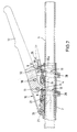
- FIG. 7 illustrates that not yet fully pulled clamping lever 12, the clamping rings 8 and 9 in their clamped position.
- the tension lever 12 is only between the, not shown, forward position in the direction of the mother animal and the Moved position shown in Figure 7, the latter End position due to the attachment of the neck 32 of the clamping lever 12 is specified on the approach 31 of the trigger lever 29.
- the clamping lever 12 is released and it presses the Operator with their normally operating the clamping lever Hand the leg 32 of the release lever 29, the leg parts 35a and 35b the clamping ring 9 from the position shown in swivel the position perpendicular to the longitudinal axis of the rod 1. During the pivoting of the lever 29, it also arrives Approach 31 from the path of movement of the approach 33 of the clamping lever 12.
Landscapes
- Health & Medical Sciences (AREA)
- Life Sciences & Earth Sciences (AREA)
- Veterinary Medicine (AREA)
- Surgery (AREA)
- Engineering & Computer Science (AREA)
- Wood Science & Technology (AREA)
- Zoology (AREA)
- Animal Behavior & Ethology (AREA)
- General Health & Medical Sciences (AREA)
- Public Health (AREA)
- Accommodation For Nursing Or Treatment Tables (AREA)
Description
Die Erfindung betrifft ein Gerät zur Viehgeburtshilfe, mit einer gegen den Körper eines Muttertieres abstützbaren Ansatzstütze, die eine Stange aufnimmt, mit zwei auf der Stange angeordneten, abwechselnd verschiebbaren und feststellbaren hülsenförmigen Teilen, wobei jedes hülsenförmige Teil einen von der Stange durchsetzten Klemmring aufnimmt, der mittels Federkraft im Sinne einer das hülsenförmige Teil und die Stange festlegenden Klemmstellung vorgespannt ist, mit mindestens zwei Halteeinrichtungen, die an mindestens einem der beiden hülsenförmigen Teile befestigt sind und in Zugrichtung eine Anspannung von mit den Halteeinrichtungen verbindbaren Beinschlingen für das Jungtier ermöglichen, sowie in einem der hülsenförmigen Teile ein Spannhebel schwenkbar gelagert ist, der in Abstand von seiner Schwenkachse ein Zwischenglied schwenkbar aufnimmt und das Zwischenglied gleichfalls im anderen hülsenförmigen Teil schwenkbar gelagert ist, mit einer Einrichtung zum Lösen der festgelegten hülsenförmigen Teile, die ein in einem der hülsenförmigen Teile gelagertes, von Hand entgegen Federkraft betätigbares Auslöseelement aufweist, mittels dessen der Klemmring dieses hülsenförmige Teiles aus der Klemmstellung bewegbar ist, wobei der Spannhebel im Bereich jedes hülsenförmigen Teiles einen Ansatz aufweist und der eine Ansatz in Kontakt mit dem Auslöseelement des einen hülsenförmigen Teiles und der andere Ansatz in Kontakt mit dem Klemmring des anderen hülsenförmigen Teiles bringbar ist, sowie der andere Ansatz beim Überführen des Spannhebels in seine vollständig eingeschwenkte Stellung in Kontakt mit dem Klemmring des anderen hülsenförmigen Teiles gelangt und diesen in seine nicht geklemmte Stellung überführt.The invention relates to a device for cattle obstetrics, with a neck support that can be supported against the body of a mother animal, which picks up a pole with two arranged on the pole, alternately displaceable and lockable sleeve-shaped Split, with each sleeve-shaped part one off the bar enforced clamping ring, which means spring force in the sense one defining the sleeve-shaped part and the rod Is clamped, with at least two holding devices, on at least one of the two sleeve-shaped Parts are attached and in the direction of tension with the holding devices connectable leg slings for the Allow young animals, as well as in one of the sleeve-shaped parts a clamping lever is pivotally mounted at a distance from an intermediate link pivotally receives its pivot axis and the intermediate link also in the other sleeve-shaped part is pivotally mounted, with a device for releasing the fixed sleeve-shaped parts, one in one of the sleeve-shaped Parts stored, can be operated by hand against spring force Has release element, by means of which the clamping ring this sleeve-shaped part is movable out of the clamping position, the tensioning lever in the area of each sleeve-shaped part has an approach and one approach in contact with the Tripping element of one sleeve-shaped part and the other Approach in contact with the other sleeve's clamping ring Part is feasible, as well as the other approach when transferring the Clamping lever in its fully swiveled in position Contact with the clamping ring of the other sleeve-shaped part arrives and transferred to its unclamped position.
Ein derartiges Gerät zur Viehgeburtshilfe ist aus der DE 44 41 795 C1 bekannt. Dort verhindert der Klemmring des einen hülsenförmigen Teiles in seiner Klemmstellung, daß der Spannhebel in seine vollständig eingeschwenkte Stellung überführt werden kann, da der Ansatz des Spannhebels die Stirnfläche dieses Klemmringes kontaktiert. Im einen hülsenförmigen Teil ist ein von Hand entgegen Federkraft betätigbarer Stößel verschiebbar gelagert, der stirnseitig in Kontakt mit dem Klemmring des einen hülsenförmigen Teiles bringbar ist und dieses aus seiner Klemmstellung bewegt, wobei der Klemmring auch aus den Bewegungsweg des am Spannhebel angebrachten Ansatzes gelangt, so daß dieser in seine vollständig eingeschwenkte Stellung überführt werden kann und damit auch der andere Ansatz des Schwenkhebels wirksam werden kann, der den Klemmring des anderen hülsenförmigen Teiles aus seiner Klemmstellung bewegt. Damit sind die beiden hülsenförmigen Teile bezüglich der Stange gelöst und können in Richtung der Ansatzstütze bzw. des Muttertieres rutschen, so daß die Anspannung der Beinschlingen für das Jungtier reduziert wird.Such a device for cattle obstetrics is from DE 44 41 795 C1 known. There the clamping ring prevents the one sleeve-shaped Part in its clamping position that the clamping lever in its fully swiveled-in position can be transferred, because the approach of the clamping lever the end face of this clamping ring contacted. In one sleeve-shaped part is one by hand plunger that can be actuated against spring force, the end face in contact with the clamping ring of a sleeve-shaped Part can be brought and this from its clamped position moves, the clamping ring also from the path of movement of the Approach lever attached approach so that this in his fully pivoted position can be transferred and so that the other approach of the pivot lever also take effect can of the clamping ring of the other sleeve-shaped part moved to its clamped position. So that the two are sleeve-shaped Parts released with respect to the rod and can be moved in the direction of the Neck support or the mother animal slip, so that the tension the leg loops for the young animal are reduced.
Bei diesem Gerät muß das als Stößel ausgebildete Auslöseelement in unmittelbarer Nähe des Spannhebels bedient werden. Hierbei besteht die Gefahr, daß der beim Überführen der Klemmringe aus ihrer Klemmstellung in die vollständig eingeschwenkte Stellung schwenkende Spannhebel den mit dem Gerät Arbeitenden verletzt. Die Ausbildung des Auslöseelementes als Stößel macht es überdies erforderlich, erhebliche Auslösekräfte aufzubringen, wenn die in die Halteeinrichtungen eingehängten Beinschlingen gespannt sind. Des weiteren weist bei dem Gerät der dem einen hülsenförmigen Teil zugeordnete Klemmring die Funktion des Anschlages für den Ansatz am Spannhebel auf. Erfolgt beispielsweise infolge Verschmutzung die Rückstellung dieser Klemmscheibe unter Federkraft nicht einwandfrei, so ist auch die Anschlagfunktion dieses Klemmringes für den Ansatz am Spannhebel nicht gewährleistet.In this device, the trigger element designed as a plunger be operated in the immediate vicinity of the tensioning lever. Here there is a risk that the transferring of the clamping rings their clamping position in the fully swiveled-in position pivoting clamping lever injured the person working with the device. The formation of the trigger element as a plunger also makes it required to exert significant triggering forces when the in the holding devices are attached to the leg slings. Furthermore, the device has a sleeve-shaped one Part assigned clamping ring the function of the stop for the Approach on the tension lever. For example, as a result of Contamination the provision of this clamping disc under Spring force is not perfect, so is the stop function this clamping ring for the attachment to the clamping lever is not guaranteed.
Aus der EP 0 608 790 A1 ist ein Gerät zur Viehgeburtshilfe bekannt, bei dem eine Einrichtung zum Lösen der beiden festgelegten hülsenförmigen Teile vorgesehen ist, die als Auslöseelement ein schwenkbar in einem hülsenförmigen Teil gelagerten Auslösehebel aufweist. Beim Verschwenken des Auslösehebels, der in dem dem Schwenkhebel abgewandten Bereich des einen hülsenförmigen Teiles gelagert ist, wird der diesem hülsenförmigen Teil zugeordnete Klemmring in seine nicht geklemmte Stellung verschwenkt, wodurch die Klemmverbindung zwischen diesem hülsenförmigen Teil und der Stange aufgehoben wird. Infolgedessen bewegt sich dieses hülsenförmige Teil in Richtung des anderen hülsenförmigen Teiles und betätigt einen im anderen hülsenförmigen Teil in dessen Längsrichtung verschieblich gelagerten Stößel, der gegen den im anderen hülsenförmigen Teil gelagerten Klemmring bewegt wird und diesen in seine nicht geklemmte Stellung überführt. Damit ist auch das andere hülsenförmige Teil relativ zur Stange verschiebbar. Die Auslösung erfolgt bei diesem Gerät damit nach einem anderen Wirkprinzip als dies für das Gerät nach der DE 44 41 795 C1 vorgeschlagen wird, somit unabhängig vom Schwenkhebel.EP 0 608 790 A1 describes a device for cattle obstetrics known in which a device for solving the two set sleeve-shaped parts is provided as a trigger element a pivotally mounted in a sleeve-shaped part Has release lever. When pivoting the release lever, the in the region of the one sleeve-shaped area facing away from the swivel lever Part is stored, the sleeve-shaped part assigned clamping ring pivoted into its unclamped position, whereby the clamping connection between this sleeve-shaped Part and the rod is lifted. As a result, moved this sleeve-shaped part in the direction of the other sleeve-shaped Part and actuates one in the other sleeve-shaped Part of the plunger slidably mounted in the longitudinal direction thereof, the against the bearing ring in the other sleeve-shaped part is moved and this in its unclamped position transferred. So that the other sleeve-shaped part is relative slidable to the bar. This device triggers thus according to a different operating principle than this for the device DE 44 41 795 C1 is proposed, thus regardless of Swivel lever.
Es ist Aufgabe der vorliegenden Erfindung, ein Gerät zur Viehgeburtshilfe der eingangs genannten Art so weiter zu bilden, daß bei baulich besonders einfacher Gestaltung der Einrichtung zum Lösen der festgelegten hülsenförmigen Teile eine unkomplizierte und sichere Betätigung der Einrichtung gewährleistet ist.It is an object of the present invention to provide a device for To further develop cattle obstetrics of the type mentioned at the beginning, that with structurally particularly simple design of the facility an uncomplicated way to loosen the fixed sleeve-shaped parts and ensure safe operation of the device is.
Gelöst wird die Aufgabe bei einem Gerät zur Viehgeburtshilfe der eingangs genannten Art dadurch, daß das Auslöseelement als schwenkbar in einem hülsenförmigen Teil gelagerter Auslösehebel ausgebildet ist, wobei der Auslösehebel einen Ansatz aufweist, der in einer ersten Stellung des Auslösehebels in den Schwenkweg des einen Ansatzes des Spannhebels ragt und ein vollständiges Einschwenken des Spannhebels verhindert, sowie der Auslösehebel beim Überführen in eine zweite Stellung, in der er den Klemmring des einen hülsenförmigen Teiles aus der Klemmstellung bewegt, aus dem Schwenkweg des Ansatzes des Spannhebels zu dessen vollständigem Einschwenken bewegt wird.The task is solved with a device for cattle obstetrics type mentioned in that the trigger element as Trigger lever pivotally mounted in a sleeve-shaped part is formed, the trigger lever having a shoulder, the in a first position of the release lever in the swivel path one end of the tension lever protrudes and a complete one Swiveling of the tensioning lever prevented, as well as the release lever when transferring to a second position in which he has the clamping ring one of the sleeve-shaped parts moved out of the clamping position, from the swivel path of the approach of the tensioning lever to it is completely swung in.
Bei dem erfindungsgemäßen Gerät zur Viehgeburtshilfe dient der Ansatz des Auslösehebels in dessen nicht betätigter Stellung dem Blockieren des Spannhebels, indem der Ansatz des Auslösehebels in den Schwenkweg des Ansatzes des Spannhebels ragt. Der Spannhebel bzw. dessen Ansatz kontaktiert demzufolge bei diesem Zustand den Klemmring nicht. Die Beschränkung des Schwenkweges des Spannhebels hängt damit nur von der Position des Auslöseelementes bzw. dessen Ansatzes ab. Aufgehoben wird die Klemmung des dem Auslöseelement zugeordneten Klemmringes unmittelbar durch das Auslöseelement. Beim Betätigen des Auslöseelementes von Hand schwenkt dieses, wobei der Ansatz des Auslöseelementes aus dem Bewegungsweg des Spannhebels geschwenkt wird, womit dieser nunmehr beim Verschieben des gelösten hülsenförmigen Teiles auf der Stange vollständig einschwenken kann und hierbei der andere Ansatz des Spannhebels den Klemmring des anderen hülsenförmigen Teiles in die nicht geklemmte Stellung überführt. Die Betätigung des Auslöseelementes erfolgt dabei nicht in einer geradlinigen Bewegung, sondern mittels einer Schwenkbewegung. Durch die Ausbildung des Auslöseelementes als Auslösehebel können dessen Hebelarme optimal gewählt werden, um mit geringem Krafteinsatz das Aufheben der Klemmung desjenigen Klemmringes zu erreichen, der dem das Auslöseelement aufnehmenden hülsenförmigen Teil zugeordnet ist.In the device for cattle obstetrics according to the invention, the Approach of the release lever in its inactive position Block the tension lever by the approach of the release lever protrudes into the swivel path of the approach of the tensioning lever. The Clamping lever or its approach therefore contacts with this Condition of the clamping ring is not. The limitation of the swivel path the clamping lever depends only on the position of the release element or its approach. The clamping is released the clamping ring assigned to the trigger element immediately through the trigger element. When actuating the trigger element by hand this pivots, the approach of the trigger element is pivoted out of the path of movement of the clamping lever, with what this now when moving the released sleeve-shaped Part fully swiveled on the rod and this the other approach of the tensioning lever the other's clamping ring sleeve-shaped part transferred to the unclamped position. The triggering element is not actuated in one rectilinear movement, but by means of a swivel movement. By designing the trigger element as a trigger lever the lever arms can be optimally selected to with little Use of force to release the clamping of that clamping ring reach that of the sleeve-shaped receiving the release element Part is assigned.
Eine besondere Gestaltung sieht vor, daß der Auslösehebel als Winkelhebel ausgebildet ist, wobei der Auslösehebel im Winkelbereich seiner Schenkel schwenkbar im dem Spannhebel zugewandten Bereich des einen hülsenförmigen Teils gelagert ist. Hierdurch ist der Schenkel, der dem Kontaktieren des Klemmringes dient, in dessen unmittelbarer Nähe gelagert, im wesentlichen parallel zu diesen. Der Ansatz des Auslösehebels ist bevorzugt im Bereich der Schwenkachse des Auslösehebels angeordnet. Durch die seitlich versetzte Anordnung des mittels Hand zu beaufschlagenden Schenkels des Auslösehebels sind Unfallgefahren für den das Gerät Bedienenden weitgehend eliminiert, da beim Lösen der beiden hülsenförmigen Teile der Spannhebel neben dem von Hand beaufschlagten Schenkel des Auslösehebels einschwenkt. Zweckmäßig ist der dem Kontakt mit dem Klemmring des einen hülsenförmigen Teiles dienende Schenkel zweiteilig ausgebildet, wobei jedes Schenkelteil seitlich der Stange angeordnet ist. Hierdurch können symmetrisch zur Mittellängsachse der Stange die Kräfte zum Aufheben der Klemmung des Klemmringes in dem hülsenförmigen Teil, das das Auslöseelement aufweist, aufgebracht werden.A special design provides that the release lever as Angle lever is formed, the trigger lever in the angular range its leg pivotable in the tension lever facing Area of a sleeve-shaped part is mounted. Hereby is the leg that serves to contact the clamping ring in stored in its immediate vicinity, essentially parallel to this. The approach of the release lever is preferred in the area the pivot axis of the release lever. Through the laterally offset arrangement of the to be loaded by hand Leg of the trigger lever are accident hazards for that Device operators largely eliminated because when loosening the two sleeve-shaped parts of the tensioning lever next to that by hand pivoted acted arm of the trigger lever. Appropriately is the contact with the clamping ring of a sleeve-shaped Part serving leg formed in two parts, each Leg part is arranged on the side of the rod. Hereby the forces can be symmetrical to the central longitudinal axis of the rod to release the clamping of the clamping ring in the sleeve-shaped Part, which has the trigger element, are applied.
Weitere Merkmale der Erfindung sind in den Unteransprüchen, der Beschreibung der Figuren und den Figuren selbst dargestellt, wobei bemerkt wird, daß alle Einzelmerkmale und alle Kombinationen von Einzelmerkmalen erfindungswesentlich sind.Further features of the invention are in the dependent claims Description of the figures and the figures themselves, it being noted that all individual features and all combinations of individual features are essential to the invention.
In den Figuren ist die Erfindung anhand einer Ausführungsform beispielsweise dargestellt, ohne auf diese beschränkt zu sein. Es zeigt:
- Figur 1
- eine Seitenansicht auf die erfindungsrelevanten Teile des Gerätes, verdeutlicht bei vollständig durchgezogenem Spannhebel,
Figur 2- eine Draufsicht des Gerätes nach Figur 1,
Figur 3- einen Schnitt durch das Gerät gemäß der Linie III-III
in
Figur 2, Figur 4- einen Schnitt durch das Gerät gemäß der Linie IV-IV in
Figur 3, Figur 5- einen Schnitt durchd das Gerät gemäß der Linie V-V in
Figur 3, Figur 6- einen Schnitt durch das Gerät gemäß der Linie VI-VI in
Figur 3 und - Figur 7
- einen Schnitt durch das Gerät, mit einer Schnittführung
gemäß der Linie III-III in
Figur 2, allerdings veranschaulicht bei noch nicht vollständig durchgezogenem Spannhebel.
- Figure 1
- 2 shows a side view of the parts of the device relevant to the invention, illustrated with the tension lever fully pulled through,
- Figure 2
- 2 shows a top view of the device according to FIG. 1,
- Figure 3
- 3 shows a section through the device along the line III-III in FIG. 2,
- Figure 4
- 3 shows a section through the device according to line IV-IV in FIG. 3,
- Figure 5
- 3 shows a section through the device along the line VV in FIG. 3,
- Figure 6
- a section through the device along the line VI-VI in Figure 3 and
- Figure 7
- a section through the device, with a cut along the line III-III in Figure 2, but illustrates when the tension lever is not fully pulled.
Wie der Darstellung der Figuren 1 und 2 zu entnehmen ist, weist
das für die erfindungswesentlichen Bereiche dargestellte Gerät
zur Viehgeburtshilfe eine als außen glattes Hohlrohr ausgebildete
Stange 1 auf. Die strichpunktierte Linie 2 verdeutlicht die
Position einer nicht dargestellten, gegen den Körper des
Muttertieres abstützbaren Ansatzstütze, in die die Stange mit
einem Ende einsteckbar ist. Das dem Muttertier abgekehrte Ende
der Stange ist gleichfalls nicht verdeutlicht und nimmt zweckmäßig
einen Handgriff auf. Zwischen der Ansatzstütze und dem mit
dem anderen Ende der Stange verbundenen Handgriff sind auf der
Stange 1 zwei abwechselnd verschiebbare und feststellbare,
hülsenförmige Teile 3 und 4 angeordnet. Das dem Muttertier
zugewandte hülsenförmige Teil 3 ist mit zwei diametral angeordneten
Halteeinrichtungen 5 und 6 und das andere hülsenförmige
Teil 4 mit einer Halteeinrichtung 38 versehen, die als auf der
dem Muttertier abgekehrten Seite offene Haken ausgebildet sind.
In zwei der Halteeinrichtungen 5, 6 und 38 werden entsprechend
den Anforderungen beim Geburtsverlauf die beiden Enden von
Beinschlingen gehängt, deren anderes Ende um das jeweilige Bein
des Jungtieres geschlungen sind. Die Angriffsrichtungen der in
die Halteeinrichtungen 5 und 6 eingehängten Beinschlingen sind
in der Darstellung der Figur 2 mit strichpunktierten Linien
veranschaulicht. Die hülsenförmigen Teile 3 und 4 sind in
nachfolgend noch näher zu beschreibender Art und Weise mittels
Klemmringen 8 und 9 festlegbar, die von der Stange 1 durchsetzt
werden. Zur schwenkbaren Aufnahme des jeweiligen Klemmringes 8
bzw. 9 weist das jeweilige hülsenförmige Teil 3 bzw. 4 eine von
der Seite gesehen, im wesentlichen V-förmige Tasche 10 bzw. 11
(siehe Figur 3) auf. Der Öffnungsdurchmesser des jeweiligen
Klemmringes 8 bzw. 9 ist geringfügig größer als der Außendurchmesser
der Stange 1, so daß die hülsenförmigen Teile 3 und 4,
bei senkrecht zur Stange 1 orientierten Klemmringen 8 und 9,
frei und dabei weitgehend spielfrei auf der Stange 1 in deren
Längsrichtung gleiten können, hingegen eine Schrägstellung der
Klemmringe 8 und 9 aus dieser in den Figuren 1 und 2 gezeigten
Position zum Festlegen der hülsenförmigen Teile 3 und 4 relativ
zur Stange 1 führt.As can be seen from the illustration in FIGS. 1 and 2, points
the device shown for the areas essential to the invention
for cattle obstetrics a hollow tube designed as smooth on the outside
Bar 1 on. The dash-dotted
Wie im Detail den Figuren 3 bis 6 zu entnehmen ist, ist mit dem
hülsenförmigen Teil 4 ein Spannhebel 12 schwenkbar verbunden,
wobei eine Lagerachse 13 in zwei Lagerschenkeln 14 und 15 des
hülsenförmigen Teiles 4 gehalten ist und eine Durchgangsbohrung
im Spannhebel 12 durchsetzt. In kurzem Abstand zur Lagerachse 13
des Spannhebels 12 ist ein Zwischenglied 16 mit dem Spannhebel
12 verbunden, wobei das Zwischenglied 16 gleichfalls zwei
Lagerschenkeln 17 und 18 aufweist. Im Bereich des hülsenförmigen
Teiles 4 ist eine Lagerachse 19 in den beiden Lagerschenkeln 17
und 18 gehalten und durchsetzt eine Durchgangsbohrung im
Spannhebel 12. Im Bereich des hülsenförmigen Teiles 3 ist eine
Lagerachse 20 angeordnet, die in den beiden Lagerschenkeln 17
und 18 des Zwischengliedes 16 gehalten ist und eine Durchgangsbohrung
eines Ansatzes 21 des hülsenförmigen Teiles 3 durchsetzt.As can be seen in detail in FIGS. 3 to 6, the
sleeve-shaped part 4 a clamping
Wie insbesondere der Darstellung der Figur 3 zu entnehmen ist,
weist jedes hülsenförmige Teil 3 bzw. 4 auf der dem Muttertier
abgewandten Seite eine Sackbohrung 22 zur verschieblichen
Aufnahme eines Stößelelementes 23 bzw. 24 auf. Das jeweilige
Stößelelement 23 bzw. 24 ist durch eine Stößelplatte 25 und eine
die Sackbohrung 24 durchsetzende Stößelstange 26 gebildet. Eine
Druckspiralfeder 27 umschließt die jeweilige Stößelstange 26 und
stützt sich an der jeweiligen Stößelplatte 25 und dem Bohrungsgrund
der Sackbohrung 22 ab, wodurch das jeweilige, federbeaufschlagte
Stößelelement 23 bzw. 24 den Klemmring 8 bzw. 9 auf
seiner dem Taschenboden 28 abgewandten Seite kontaktiert und
damit den Klemmring 8 bzw. 9 in Richtung seiner Klemmstellung
vorspannt.As can be seen in particular from the illustration in FIG. 3,
each sleeve-shaped
Die Figur 3 verdeutlicht, daß das hülsenförmige Teil 4 im
Bereich seines dem Handgriff für die Stange 1 zugewandten Endes,
somit auf der dem Stößelelement 24 abgewandten Seite der Tasche
11 ein als Hebel 29 ausgebildetes Auslöseelement aufweist. Der
Auslösehebel 29 ist schwenkbar im hülsenförmigen Teil 4 gelagert.
Er weist im Bereich seiner Schwenkachse 30 einen Ansatz 31
auf und ausgehend von der Schwenkachse 30 zwei im wesentlichen
im rechten Winkel zueinander angeordnete Schenkel 32 und 35. Der
mittels Hand zu beaufschlagende Schenkel verläuft etwa parallel
zur Längsachse der Stange 1 zwischen dieser und ist mit einer
Griffmulde 36 versehen. Der andere Schenkel 35 ist zweiteilig
ausgebildet, wobei jedes Schenkelteil 35a und 35b seitlich der
Stange 1 innerhalb der Tasche 11 angeordnet ist. Beim Niederdrücken
des Schenkels 32 kontaktieren die beiden Schenkelteile
35a und 35b den in der Tasche 11 angeordneten Klemmring 9 und
verschwenken diesen von seiner Klemmstellung in seine bezüglich
der Stange 1 nicht geklemmte Stellung. Nicht gezeigt ist in den
Figuren eine Feder, die den Auslösehebel 29 derart beaufschlagt,
daß dessen Schenkel 35 von der Ansatzstütze weg bzw. dessen
Schenkel 32 zum Spannhebel 12 hin beaufschlagt wird.Figure 3 illustrates that the sleeve-shaped
Figur 3 verdeutlicht das erfindungsgemäße Gerät zur Viehgeburtshilfe
bei maximal durchgezogenem Spannhebel. Um eine Verschiebung
der hülsenförmige Teile 3 und 4 auf der Stange von der
Ansatzstütze weg, somit nach rechts, und damit eine Anspannung
der Beinschlingen zu erreichen, müßte somit der Spannhebel 12,
ausgehend von der in dieser Figur gezeigten Position entgegen
dem Uhrzeigersinn um etwas mehr als 90° verschwenkt werden,
wobei zunächst die Klemmung der hülsenförmigen Teile 3 und 4 auf
der Stange erzielt wird.Figure 3 illustrates the cattle obstacle device according to the invention
with maximum tension lever pulled through. About a shift
the sleeve-shaped
Wie ferner der Darstellung der Figur 3 zu entnehmen ist, sind
bei voll durchgezogenem Spannhebel 12 die Klemmringe 8 und 9 in
eine Stellung überführt, in der die Stange 1 diese mit Spiel
durchsetzt und damit keine Klemmung zwischen Stange 1 und den
hülsenförmigen Teilen 3 und 4 mittels der Klemmringe 8 und 9
herbeigeführt ist. In dieser Stellung sind die Stößelelemente 23
und 24 weitgehend in die hülsenförmigen Teile 3 und 4 eingeschoben.
Ferner befindet sich der Schenkel 32 des Auslösehebels 29
in seiner von Hand niedergedrückten Stellung, bei der die
Schenkelteile 35a und 35b des Auslösehebels 29 den Klemmring 9
auf der dem Stößelelement 24 abgewandten Seite kontaktieren. In
dieser Position hintergreift ein am Schwenkhebel 12 angeordneter
Ansatz 33 den Ansatz 31 des Auslösehebels 29 auf dessen den
Klemmring 9 zugewandter Seite. In dieser in Figur 3 gezeigten
Position liegt ein weiterer, im Bereich der Lagerachse 13 mit
dem Spannhebel 12 verbundener Ansatz 34 an der Rückseite des im
hülsenförmigen Teil 3 gehaltenen Klemmringes 8 an, der in seine
nicht geklemmte Stellung geschwenkt ist.As can also be seen from the illustration in FIG
with the clamping
Die Darstellung der Figur 7 veranschaulicht, daß bei noch nicht
voll durchgezogenem Spannhebel 12 sich die Klemmringe 8 und 9 in
ihrer Klemmstellung befinden. Dies führt dazu, daß die hülsenförmigen
Teile 3 und 4 relativ zur Stange 1 festgelegt sind. Im
Normalbetrieb, das heißt dann, wenn die Blockierung des Gerätes
nicht aufgehoben werden soll, demnach die hülsenförmigen Teile
3 und 4 nicht in Richtung des Muttertieres geschoben werden
sollen, wird der Spannhebel 12 nur zwischen der nicht gezeigten,
vorderen, in Richtung des Muttertieres bewegten Stellung und der
in Figur 7 gezeigten Stellung bewegt, wobei diese letztgenannte
Endstellung aufgrund der Anlage des Ansatzes 32 des Spannhebels
12 am Ansatz 31 des Auslösehebels 29 vorgegeben ist. In dieser
Stellung ist der andere Ansatz 34 des Spannhebels 12 gerade noch
nicht in Kontakt mit dem Klemmring 8 des hülsenförmigen Teiles
3, so daß weder dieser Klemmring noch der andere Klemmring 9 in
ihre nicht geklemmten Stellung überführt werden können. Dies
führt dazu, daß beim Bewegen des Spannhebels 12 in Richtung des
Muttertieres das hülsenförmige Teil 4 vom dann stationären
hülsenförmigen Teil 3 wegbewegt wird, während beim Bewegen des
Spannhebels 12 vom Muttertier weg das hülsenförmige Teil 3 in
Richtung des hülsenförmigen Teiles 4 nachgezogen wird, womit
sich der Abstand der Halteeinrichtungen 5 und 6 für die Beinschlingen
vom Muttertier vergrößert.The illustration in FIG. 7 illustrates that not yet
fully pulled clamping
Sollen nun ausgehend von der in Figur 7 gezeigten Position des
Gerätes die Blockierung der Halteeinrichtungen 5 und 6 aufgehoben
werden, wird der Spannhebel 12 losgelassen und es drückt die
Bedienperson mit ihrer normalerweise den Spannhebel betätigenden
Hand den Schenkel 32 des Auslösehebels 29, wobei die Schenkelteile
35a und 35b den Klemmring 9 aus der gezeigten Stellung in
die Position senkrecht zur Längsachse der Stange 1 verschwenken.
Während des Verschwenkens des Hebels 29 gelangt auch dessen
Ansatz 31 aus dem Bewegungsweg des Ansatzes 33 des Spannhebels
12. In der Auslösestellung des Hebels 29 wird die Klemmung
zwischen dem hülsenförmigen Teil 4 und der Stange 1 aufgehoben,
so daß die über die Beinschlingen in das hülsenförmige Teil 4
eingeleitete Kraft zu einer Verschiebung dieses hülsenförmigen
Teiles 4 in Richtung des anderen hülsenförmigen Teiles 3 führt.
Die Annäherung der beiden hülsenförmigen Teile 3 und 4 bedingt
aufgrund der Lagerung des Spannhebels 12 im hülsenförmigen Teil
4, daß der Spannhebel 12 im Bereich seines Ansatzes 33 am Ansatz
31 des Auslösehebels 29 vorbei in die in Figur 1 gezeigte
Stellung einschwenkt. Mit dem vollständigen Einschwenken des
Spannhebels 12, von der in Figur 7 gezeigten Position in die
Position der Figur 1, verschiebt dann auch der weitere Ansatz 34
am Spannhebel 12 den Klemmring 8 des hülsenförmigen Teiles 3 in
die senkrecht zur Längsachse der Stange 1 orientierte, nicht
klemmende Stellung.Should now proceed from the position of the
Device the blocking of the
In der Position des Spannhebels 12 gemäß Figur 3 verhindert der
Ansatz 33 am Spannhebel 12, daß der federbeaufschlagte Klemmring
9 wieder in seine geklemmte Stellung überführt wird. Soll eine
Klemmung der hülsenförmigen Teile 3 und 4 mit der Stange 1
erneut herbeigeführt werden, wird bei nicht betätigtem Auslösehebel
29 der Spannhebel 12 in Richtung des Muttertieres
verschwenkt, womit der Ansatz 34 außer Eingriff mit dem Klemmring
8 gelangt und der Ansatz 31 des Auslösehebels 29 wieder in
den Bewegungsweg des Ansatzes 33 des Spannhebels 12 zurückbewegt
wird, wie es in Figur 7 gezeigt ist.In the position of the
Claims (5)
- Implement for veterinary obstetrics, with a rest attachment which can be supported against the body of the mother animal and which receives a rod (1), with two alternately displaceable and lockable sleeve parts (3, 4) arranged on the rod (1), each holding a jamming ring (8, 9) through which the rod (1) passes and which is tensioned by the force of a spring keeping it in a jamming position locking the sleeve part (3, 4) to the rod (1), with at least two holding devices (5, 6) which are fixed to at least one of the two sleeve parts (3, 4) and which allow traction to be exerted on leg slings for the baby animal which are attachable to the holding devices (5, 6), a cocking lever (12) being pivotably mounted in one of the sleeve parts (3, 4) which at a distance from its pivot (13) pivotably holds an intermediate link (16) which is also pivotably mounted in the other sleeve part (3), with a device for releasing the locked sleeve parts (3, 4) which has a release element (29) which is mounted in one of the sleeve parts (3, 4) and is manually operable against spring force and by means of which the jamming ring (9) of this sleeve part (4) can be moved out of the jamming position, the cocking lever (12) having a catch projection (34, 33) in the region of each sleeve part (3, 4), one catch projection (33) being capable of being brought into contact with the release element (29) of one sleeve part (4) and the other catch projection (34) being capable of being brought into contact with the jamming ring (8) of the other sleeve part (3), said other catch projection (34) coming into contact with the jamming ring (8) of the other sleeve part (3) and shifting it into its unjammed position when the cocking lever (12) is shifted into its fully pivoted position, characterized in that the release element (29) is formed as an engaging and disengaging lever (29) pivotably mounted in one sleeve part (4) and having a latch (31) which in a first position of the release lever (29) projects into the way of a catch projection (33) of the cocking lever (12) and prevents the cocking lever (12) from being fully depressed, and the release lever (29) when shifted into a second position, in which it moves the jamming ring (9) of one sleeve part (4) out of the jamming position, is moved out of the way of the catch projection (33) of the cocking lever (12), allowing the latter to be fully depressed.
- Implement according to Claim 1, characterized in that the release lever (29) is formed as a bell-crank lever pivotably mounted in the elbow region between its arms (32, 35) in the region orientated towards the cocking lever (12) of one sleeve part (4).
- Implement according to Claim 2, characterized in that the latch (31) of the release lever (29) is arranged in the region of the pivot (30) of the release lever (29).
- Implement according to Claim 2 or Claim 3, characterized in that the arm (32) of the release lever (29) that is intended to be acted on manually is laterally offset with respect to the cocking lever (12).
- Implement according to any one of Claims 2 to 4, characterized in that the arm (35) of the release lever (29) that is capable of being brought into contact with the jamming ring (9) of one sleeve part (4) is formed in two parts (35a, 35b) disposed on either side of the rod (1).
Applications Claiming Priority (2)
| Application Number | Priority Date | Filing Date | Title |
|---|---|---|---|
| DE19734956A DE19734956C1 (en) | 1997-08-13 | 1997-08-13 | Cattle birth aid with support, bar and two sleeves |
| DE19734956 | 1997-08-13 |
Publications (2)
| Publication Number | Publication Date |
|---|---|
| EP0901774A1 EP0901774A1 (en) | 1999-03-17 |
| EP0901774B1 true EP0901774B1 (en) | 2001-09-12 |
Family
ID=7838772
Family Applications (1)
| Application Number | Title | Priority Date | Filing Date |
|---|---|---|---|
| EP98112114A Expired - Lifetime EP0901774B1 (en) | 1997-08-13 | 1998-07-01 | Device for assisting parturition of animals |
Country Status (2)
| Country | Link |
|---|---|
| EP (1) | EP0901774B1 (en) |
| DE (2) | DE19734956C1 (en) |
Families Citing this family (4)
| Publication number | Priority date | Publication date | Assignee | Title |
|---|---|---|---|---|
| BRPI0613126A2 (en) | 2005-06-30 | 2012-12-04 | Kelsey Hayes Co | master cylinder braking system for applying pressurized hydraulic brake fluid |
| CN101896382A (en) | 2007-10-29 | 2010-11-24 | 凯尔西-海耶斯公司 | Hydraulic brake system with controlled boost |
| US8661812B2 (en) | 2010-02-03 | 2014-03-04 | Kelsey-Hayes Company | Hydraulic brake system with controlled boost |
| WO2012058330A2 (en) | 2010-10-26 | 2012-05-03 | Kelsey-Hayes Company | Hydraulic brake system with controlled boost |
Family Cites Families (2)
| Publication number | Priority date | Publication date | Assignee | Title |
|---|---|---|---|---|
| DE4301857C1 (en) * | 1993-01-25 | 1994-06-30 | Rheintechnik Weiland & Kaspar | Cattle obstetrics device |
| DE4441795C1 (en) * | 1994-11-24 | 1996-06-20 | Rheintechnik Weiland & Kaspar | Cattle obstetrics device |
-
1997
- 1997-08-13 DE DE19734956A patent/DE19734956C1/en not_active Expired - Lifetime
-
1998
- 1998-07-01 EP EP98112114A patent/EP0901774B1/en not_active Expired - Lifetime
- 1998-07-01 DE DE59801433T patent/DE59801433D1/en not_active Expired - Lifetime
Also Published As
| Publication number | Publication date |
|---|---|
| EP0901774A1 (en) | 1999-03-17 |
| DE19734956C1 (en) | 1998-08-20 |
| DE59801433D1 (en) | 2001-10-18 |
Similar Documents
| Publication | Publication Date | Title |
|---|---|---|
| DE2328230C3 (en) | Transmission linkage for vehicles, in particular commercial vehicles, with tiltable driver's cabs, intended in particular for shifting a gearbox | |
| DE20007177U1 (en) | Medical instrument with lockable power transmission element | |
| DE29623113U1 (en) | Axial handle for surgical, especially endoscopic, instruments | |
| DE1919472A1 (en) | Tool for tensioning a tape wrapped around an object and for connecting and cutting the tape ends | |
| DE60002097T2 (en) | FIFTH WHEEL ARRANGEMENT | |
| DE3026963A1 (en) | Shift head for actuating a gear shift | |
| DE4010144A1 (en) | DEVICE FOR TROUBLING PLANTS | |
| DE10014063A1 (en) | Medical or dental treatment chair or a headrest for such a treatment chair | |
| DE3523058C2 (en) | LENGTH ADJUSTABLE SAFETY SKI BINDING | |
| DE2732575C2 (en) | Locking device | |
| DE3239948C1 (en) | Device for operating a slide lock | |
| DE2326332C3 (en) | Zipper slider holding device | |
| EP0901774B1 (en) | Device for assisting parturition of animals | |
| DE2619031B1 (en) | LENGTH-ADJUSTABLE TOP ARM | |
| DE19854943A1 (en) | Tool for connection to hydraulic compression unit | |
| DE10221941A1 (en) | Device for fixing a tool on a hoist | |
| DE4309569C1 (en) | Handle for a tubular surgical instrument | |
| DE69201889T2 (en) | Safety ski binding. | |
| DE3739254A1 (en) | Medical, in particular surgical, instrument | |
| EP1086835B1 (en) | Trailer coupling | |
| EP0941888A2 (en) | Longitudinal adjusting device for seats, particularly for vehicle seats | |
| DE4441795C1 (en) | Cattle obstetrics device | |
| DE4301857C1 (en) | Cattle obstetrics device | |
| EP0548302B1 (en) | Locking system for a forceps like instrument | |
| EP0513485A1 (en) | Device for cutting blood flow in a member |
Legal Events
| Date | Code | Title | Description |
|---|---|---|---|
| PUAI | Public reference made under article 153(3) epc to a published international application that has entered the european phase |
Free format text: ORIGINAL CODE: 0009012 |
|
| 17P | Request for examination filed |
Effective date: 19981229 |
|
| AK | Designated contracting states |
Kind code of ref document: A1 Designated state(s): DE ES FR GB IE IT NL PT |
|
| AX | Request for extension of the european patent |
Free format text: AL;LT;LV;MK;RO;SI |
|
| RIN1 | Information on inventor provided before grant (corrected) |
Inventor name: ANDRETZKI, RAINER Inventor name: FANNEI, JOSEF |
|
| AKX | Designation fees paid |
Free format text: DE ES FR GB IE IT NL PT |
|
| RAP1 | Party data changed (applicant data changed or rights of an application transferred) |
Owner name: RHEINTECHNIK WEILAND & KASPAR GMBH & CO. KG |
|
| GRAG | Despatch of communication of intention to grant |
Free format text: ORIGINAL CODE: EPIDOS AGRA |
|
| 17Q | First examination report despatched |
Effective date: 20001127 |
|
| GRAG | Despatch of communication of intention to grant |
Free format text: ORIGINAL CODE: EPIDOS AGRA |
|
| GRAH | Despatch of communication of intention to grant a patent |
Free format text: ORIGINAL CODE: EPIDOS IGRA |
|
| GRAH | Despatch of communication of intention to grant a patent |
Free format text: ORIGINAL CODE: EPIDOS IGRA |
|
| GRAA | (expected) grant |
Free format text: ORIGINAL CODE: 0009210 |
|
| AK | Designated contracting states |
Kind code of ref document: B1 Designated state(s): DE ES FR GB IE IT NL PT |
|
| PG25 | Lapsed in a contracting state [announced via postgrant information from national office to epo] |
Ref country code: GB Free format text: LAPSE BECAUSE OF FAILURE TO SUBMIT A TRANSLATION OF THE DESCRIPTION OR TO PAY THE FEE WITHIN THE PRESCRIBED TIME-LIMIT Effective date: 20010912 |
|
| REG | Reference to a national code |
Ref country code: IE Ref legal event code: FG4D Free format text: GERMAN |
|
| REF | Corresponds to: |
Ref document number: 59801433 Country of ref document: DE Date of ref document: 20011018 |
|
| PG25 | Lapsed in a contracting state [announced via postgrant information from national office to epo] |
Ref country code: PT Free format text: LAPSE BECAUSE OF FAILURE TO SUBMIT A TRANSLATION OF THE DESCRIPTION OR TO PAY THE FEE WITHIN THE PRESCRIBED TIME-LIMIT Effective date: 20011212 |
|
| ET | Fr: translation filed | ||
| GBV | Gb: ep patent (uk) treated as always having been void in accordance with gb section 77(7)/1977 [no translation filed] |
Effective date: 20010912 |
|
| PG25 | Lapsed in a contracting state [announced via postgrant information from national office to epo] |
Ref country code: ES Free format text: LAPSE BECAUSE OF FAILURE TO SUBMIT A TRANSLATION OF THE DESCRIPTION OR TO PAY THE FEE WITHIN THE PRESCRIBED TIME-LIMIT Effective date: 20020326 |
|
| PLBE | No opposition filed within time limit |
Free format text: ORIGINAL CODE: 0009261 |
|
| STAA | Information on the status of an ep patent application or granted ep patent |
Free format text: STATUS: NO OPPOSITION FILED WITHIN TIME LIMIT |
|
| 26N | No opposition filed | ||
| REG | Reference to a national code |
Ref country code: NL Ref legal event code: SD Effective date: 20110124 |
|
| REG | Reference to a national code |
Ref country code: FR Ref legal event code: TP |
|
| REG | Reference to a national code |
Ref country code: DE Ref legal event code: R081 Ref document number: 59801433 Country of ref document: DE Owner name: RHEINTECHNIK BECKER ELEKTRONIK GMBH & CO. KG, DE Free format text: FORMER OWNER: RHEINTECHNIK WEILAND & KASPAR GMBH & CO. KG MASCHINENFABRIK HERSTELLUNG UND VERTRIEB VON ELEKTRONISCHEN, MEDIZINISCHEN UND TIERMEDIZINISCHEN ARTIKELN, 56566 NEUWIED, DE Effective date: 20110406 |
|
| PGFP | Annual fee paid to national office [announced via postgrant information from national office to epo] |
Ref country code: IE Payment date: 20140723 Year of fee payment: 17 |
|
| PGFP | Annual fee paid to national office [announced via postgrant information from national office to epo] |
Ref country code: FR Payment date: 20140721 Year of fee payment: 17 |
|
| PGFP | Annual fee paid to national office [announced via postgrant information from national office to epo] |
Ref country code: IT Payment date: 20140730 Year of fee payment: 17 |
|
| REG | Reference to a national code |
Ref country code: IE Ref legal event code: MM4A |
|
| PG25 | Lapsed in a contracting state [announced via postgrant information from national office to epo] |
Ref country code: IT Free format text: LAPSE BECAUSE OF NON-PAYMENT OF DUE FEES Effective date: 20150701 |
|
| REG | Reference to a national code |
Ref country code: FR Ref legal event code: ST Effective date: 20160331 |
|
| PG25 | Lapsed in a contracting state [announced via postgrant information from national office to epo] |
Ref country code: FR Free format text: LAPSE BECAUSE OF NON-PAYMENT OF DUE FEES Effective date: 20150731 |
|
| PG25 | Lapsed in a contracting state [announced via postgrant information from national office to epo] |
Ref country code: IE Free format text: LAPSE BECAUSE OF NON-PAYMENT OF DUE FEES Effective date: 20150701 |
|
| PGFP | Annual fee paid to national office [announced via postgrant information from national office to epo] |
Ref country code: NL Payment date: 20160720 Year of fee payment: 19 |
|
| PGFP | Annual fee paid to national office [announced via postgrant information from national office to epo] |
Ref country code: DE Payment date: 20160922 Year of fee payment: 19 |
|
| REG | Reference to a national code |
Ref country code: DE Ref legal event code: R119 Ref document number: 59801433 Country of ref document: DE |
|
| REG | Reference to a national code |
Ref country code: NL Ref legal event code: MM Effective date: 20170801 |
|
| PG25 | Lapsed in a contracting state [announced via postgrant information from national office to epo] |
Ref country code: NL Free format text: LAPSE BECAUSE OF NON-PAYMENT OF DUE FEES Effective date: 20170801 Ref country code: DE Free format text: LAPSE BECAUSE OF NON-PAYMENT OF DUE FEES Effective date: 20180201 |