EP0901440B1 - Hydraulisches steuerventil für hydraulische bremsanlagen - Google Patents
Hydraulisches steuerventil für hydraulische bremsanlagen Download PDFInfo
- Publication number
- EP0901440B1 EP0901440B1 EP97921959A EP97921959A EP0901440B1 EP 0901440 B1 EP0901440 B1 EP 0901440B1 EP 97921959 A EP97921959 A EP 97921959A EP 97921959 A EP97921959 A EP 97921959A EP 0901440 B1 EP0901440 B1 EP 0901440B1
- Authority
- EP
- European Patent Office
- Prior art keywords
- spool
- housing
- valve assembly
- assembly according
- bore
- Prior art date
- Legal status (The legal status is an assumption and is not a legal conclusion. Google has not performed a legal analysis and makes no representation as to the accuracy of the status listed.)
- Expired - Lifetime
Links
- 230000000712 assembly Effects 0.000 title description 4
- 238000000429 assembly Methods 0.000 title description 4
- 230000000295 complement effect Effects 0.000 claims description 11
- 239000012530 fluid Substances 0.000 claims description 7
- 238000007789 sealing Methods 0.000 claims description 6
- 239000013536 elastomeric material Substances 0.000 claims description 3
- 238000010276 construction Methods 0.000 description 6
- 230000001419 dependent effect Effects 0.000 description 1
- 230000000694 effects Effects 0.000 description 1
- 238000004519 manufacturing process Methods 0.000 description 1
- 239000000463 material Substances 0.000 description 1
- 230000004048 modification Effects 0.000 description 1
- 238000012986 modification Methods 0.000 description 1
Images

Classifications
-
- B—PERFORMING OPERATIONS; TRANSPORTING
- B60—VEHICLES IN GENERAL
- B60T—VEHICLE BRAKE CONTROL SYSTEMS OR PARTS THEREOF; BRAKE CONTROL SYSTEMS OR PARTS THEREOF, IN GENERAL; ARRANGEMENT OF BRAKING ELEMENTS ON VEHICLES IN GENERAL; PORTABLE DEVICES FOR PREVENTING UNWANTED MOVEMENT OF VEHICLES; VEHICLE MODIFICATIONS TO FACILITATE COOLING OF BRAKES
- B60T15/00—Construction arrangement, or operation of valves incorporated in power brake systems and not covered by groups B60T11/00 or B60T13/00
- B60T15/02—Application and release valves
- B60T15/025—Electrically controlled valves
- B60T15/028—Electrically controlled valves in hydraulic systems
-
- B—PERFORMING OPERATIONS; TRANSPORTING
- B60—VEHICLES IN GENERAL
- B60T—VEHICLE BRAKE CONTROL SYSTEMS OR PARTS THEREOF; BRAKE CONTROL SYSTEMS OR PARTS THEREOF, IN GENERAL; ARRANGEMENT OF BRAKING ELEMENTS ON VEHICLES IN GENERAL; PORTABLE DEVICES FOR PREVENTING UNWANTED MOVEMENT OF VEHICLES; VEHICLE MODIFICATIONS TO FACILITATE COOLING OF BRAKES
- B60T8/00—Arrangements for adjusting wheel-braking force to meet varying vehicular or ground-surface conditions, e.g. limiting or varying distribution of braking force
- B60T8/32—Arrangements for adjusting wheel-braking force to meet varying vehicular or ground-surface conditions, e.g. limiting or varying distribution of braking force responsive to a speed condition, e.g. acceleration or deceleration
- B60T8/34—Arrangements for adjusting wheel-braking force to meet varying vehicular or ground-surface conditions, e.g. limiting or varying distribution of braking force responsive to a speed condition, e.g. acceleration or deceleration having a fluid pressure regulator responsive to a speed condition
- B60T8/36—Arrangements for adjusting wheel-braking force to meet varying vehicular or ground-surface conditions, e.g. limiting or varying distribution of braking force responsive to a speed condition, e.g. acceleration or deceleration having a fluid pressure regulator responsive to a speed condition including a pilot valve responding to an electromagnetic force
- B60T8/3615—Electromagnetic valves specially adapted for anti-lock brake and traction control systems
- B60T8/363—Electromagnetic valves specially adapted for anti-lock brake and traction control systems in hydraulic systems
- B60T8/364—Electromagnetic valves specially adapted for anti-lock brake and traction control systems in hydraulic systems switching between a number of discrete positions as a function of the applied signal, e.g. 3/3-valves
-
- Y—GENERAL TAGGING OF NEW TECHNOLOGICAL DEVELOPMENTS; GENERAL TAGGING OF CROSS-SECTIONAL TECHNOLOGIES SPANNING OVER SEVERAL SECTIONS OF THE IPC; TECHNICAL SUBJECTS COVERED BY FORMER USPC CROSS-REFERENCE ART COLLECTIONS [XRACs] AND DIGESTS
- Y10—TECHNICAL SUBJECTS COVERED BY FORMER USPC
- Y10T—TECHNICAL SUBJECTS COVERED BY FORMER US CLASSIFICATION
- Y10T137/00—Fluid handling
- Y10T137/8593—Systems
- Y10T137/86493—Multi-way valve unit
- Y10T137/86574—Supply and exhaust
- Y10T137/86622—Motor-operated
-
- Y—GENERAL TAGGING OF NEW TECHNOLOGICAL DEVELOPMENTS; GENERAL TAGGING OF CROSS-SECTIONAL TECHNOLOGIES SPANNING OVER SEVERAL SECTIONS OF THE IPC; TECHNICAL SUBJECTS COVERED BY FORMER USPC CROSS-REFERENCE ART COLLECTIONS [XRACs] AND DIGESTS
- Y10—TECHNICAL SUBJECTS COVERED BY FORMER USPC
- Y10T—TECHNICAL SUBJECTS COVERED BY FORMER US CLASSIFICATION
- Y10T137/00—Fluid handling
- Y10T137/8593—Systems
- Y10T137/87169—Supply and exhaust
- Y10T137/87217—Motor
Definitions
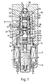
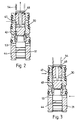
- the hydraulic control valve assembly comprises a spool valve, said spool valve comprising a spool working in a bore in a spool housing, and the housing being, in turn, sealingly received in a spool body, biasing means being incorporated for urging the spool housing in a given direction.
- the solenoid 1 comprises a solenoid body 3 in which an armature 4 is axially displaceable in response to energisation of a coil 5 surrounding the armature 4.
- the coil 5 is enclosed within a casing 6.
- a spool 40 works in co-axial bores 41 and 42 in the housing components 30 and 31, of which the bore 41 is of greater diameter than the bore 42. Specifically the bore 41 is of area 'A', and the bore 42 is of area 'B'.
- the spool 40 comprises a first spool member 43, and the second spool member 44.
- the spool members 43 and 44 are in abutment at adjacent ends.
- the spool member 43 has spaced lands 45, 46 which work in portions of the bore 41 on opposite sides of a radial port 47 in the housing component 30, with passages 48 in the spool member 43 leading from a space between the lands 45, 46 into the chamber 24.
- the spool member 43 works in the bore 42.
- the energising current applied to the coil 5 is reduced, or pulsed. This permits the armature 4 and the spool 40 to retract so that the land 45 closes the passage 47, but not through a distance sufficient for the shoulder 52 to uncover the port 53.
Landscapes
- Engineering & Computer Science (AREA)
- Physics & Mathematics (AREA)
- Transportation (AREA)
- Mechanical Engineering (AREA)
- Electromagnetism (AREA)
- Fluid Mechanics (AREA)
- Magnetically Actuated Valves (AREA)
Claims (12)
- Hydraulische Steuerventilanordnung mit einem Kolbenventil (2), bei der das Kolbenventil einen Ventilkolben (40) aufweist, der in einer Bohrung (41, 42) in einer Ventilbüchse (12) arbeitet, und die Büchse ihrerseits abdichtend in einem Ventilgehäuse aufgenommen ist, dadurch gekennzeichnet, dass Vorspannmittel vorhanden sind, um die Ventilbüchse in eine bestimmte Richtung zu drängen.
- Ventilanordnung nach Anspruch 1, bei der die Vorspannmittel dadurch gebildet sind, dass die Ventilbüchse (12) mit einer Differentialfläche ausgestattet und in einer komplementären Stufenbohrung (11) aufgenommen ist, wobei die Ventilbüchse derart angeordnet ist, dass bei Einwirkung gleicher Drucke auf die verschiedenen Flächen eine resultierende Kraft bestrebt ist, die Büchse in die bestimmte Richtung zu drängen.
- Ventilanordnung nach Anspruch 2, bei der ein Dichtdurchmesser (X) der Büchse (12) kleiner ist als ein Dichtdurchmesser (Y) im Rest der Büchse, wodurch die Ventilbüchse (12) einer resultierenden Kraft ausgesetzt wird, die sie in Richtung auf eine Bezugsfläche drängt, wenn ein Fluid hohen Drucks auf die beiden Flächen einwirkt, und wobei die Kraft die Wirkung hat, die Ventilbüchse an der Bezugsfläche festzuhalten.
- Ventilanordnung nach Anspruch 1, bei der die Vorspannmittel eine federnde Vorrichtung (70, 71) aufweisen, die zwischen dem Ventilgehäuse (10) und der Ventilbüchse (12) wirkend die Ventilbüchse vom Ventilgehäuse weg drängt.
- Ventilanordnung nach Anspruch 4, bei der die federnde Vorrichtung einen O-Ring (70) aus Elastomermaterial umfasst.
- Ventilanordnung nach Anspruch 4, in welcher die federnde Vorrichtung eine Tellerfeder (71) umfasst.
- Ventilanordnung nach einem der Ansprüche 4 bis 6, bei der die federnde Vorrichtung (70, 71) zwischen dem inneren Ende der Ventilbüchse und einer Schulter oder Stufe an einem komplementären inneren Ende des Ventilgehäuses (10) angeordnet ist.
- Ventilanordnung nach einem der vorhergehenden Ansprüche, bei der die Betätigung des Kolbenventils von einem Solenoid (1) gesteuert ist, das innerhalb eines Soleniodgehäuses (3) angeordnet ist, der Ventilkolben (40) ein Differentialprofil hat und die Bohrung (41, 42), in der er arbeitet, ein komplementäres Stufenprofil aufweist, das so gewählt ist, dass im Betrieb eine Rückstellkraft auf einen Anker des Solenoids (1) übertragen wird.
- Ventilanordnung nach einem der vorhergehenden Ansprüche, bei welcher der Ventilkolben und die Ventilbüchse je ein einziges Bauteil aufweisen.
- Ventilanordnung nach einem der Ansprüche 1 bis 8, bei welcher der Ventilkolben (40) von einem ersten und einem zweiten Ventilkolbenteil (43, 44) gebildet ist, die an einander benachbarten Enden miteinander zusammenwirken, und die Ventilbüchse (12) von einem ersten und einem zweiten Büchsenteil (30, 31), die ebenfalls an einander benachbarten Enden miteinander zusammenwirken.
- Ventilanordnung nach Anspruch 10, bei der ein Ventilkolbenteil in einer komplementären Bohrung in einem entsprechenden Büchsenteil arbeitet, und das andere Ventilkolbenteil in einer komplementären Bohrung in dem anderen Büchsenteil arbeitet.
- Ventilanordnung nach Anspruch 10 oder Anspruch 11, bei der eines der Büchsenteile (30) ein differentielles äußeres Profil aufweist, bei dem der Durchmesser des Abschnitts von größerer Fläche dem Außendurchmesser des anderen Büchsenteils (31) entspricht.
Applications Claiming Priority (3)
| Application Number | Priority Date | Filing Date | Title |
|---|---|---|---|
| GB9611534 | 1996-06-01 | ||
| GBGB9611534.0A GB9611534D0 (en) | 1996-06-01 | 1996-06-01 | Improvements in solenoid controlled valve assemblies for hydraulic braking systems |
| PCT/GB1997/001307 WO1997046433A1 (en) | 1996-06-01 | 1997-05-14 | Improvements in hydraulic control valve assemblies for hydraulic braking systems |
Publications (2)
| Publication Number | Publication Date |
|---|---|
| EP0901440A1 EP0901440A1 (de) | 1999-03-17 |
| EP0901440B1 true EP0901440B1 (de) | 2002-07-17 |
Family
ID=10794667
Family Applications (1)
| Application Number | Title | Priority Date | Filing Date |
|---|---|---|---|
| EP97921959A Expired - Lifetime EP0901440B1 (de) | 1996-06-01 | 1997-05-14 | Hydraulisches steuerventil für hydraulische bremsanlagen |
Country Status (5)
| Country | Link |
|---|---|
| US (1) | US6148859A (de) |
| EP (1) | EP0901440B1 (de) |
| DE (1) | DE69714039T2 (de) |
| GB (1) | GB9611534D0 (de) |
| WO (1) | WO1997046433A1 (de) |
Families Citing this family (1)
| Publication number | Priority date | Publication date | Assignee | Title |
|---|---|---|---|---|
| DE19710173A1 (de) * | 1997-03-12 | 1998-09-17 | Itt Mfg Enterprises Inc | Druckregelventil |
Family Cites Families (8)
| Publication number | Priority date | Publication date | Assignee | Title |
|---|---|---|---|---|
| DE2262247A1 (de) * | 1972-12-20 | 1974-06-27 | Teves Gmbh Alfred | Elektromagnetisches ventil |
| US4422475A (en) * | 1981-05-29 | 1983-12-27 | Vickers, Incorporated | Variable gain servo controlled directional valve |
| DE3934771C1 (de) * | 1989-10-18 | 1991-03-28 | Lucas Industries P.L.C., Birmingham, West Midlands, Gb | |
| US5445447A (en) * | 1990-09-28 | 1995-08-29 | Lucas Industries Public Limited Company | Hydraulic anti-locking systems for vehicles |
| JP3153231B2 (ja) * | 1990-10-16 | 2001-04-03 | ボッシュブレーキシステム株式会社 | アンチスキッドブレーキ制御装置 |
| US5163474A (en) * | 1991-11-15 | 1992-11-17 | Allied-Signal Inc. | Combination solenoid valve and integral shuttle valve |
| US5306076A (en) * | 1992-05-20 | 1994-04-26 | G. W. Lisk Company, Inc. | Proportional control valve with pressure compensation |
| GB9420150D0 (en) * | 1994-10-06 | 1994-11-23 | Lucas Ind Plc | Improvements in actuators for vehicle hydraulic braking systems of the brake-by-wire type |
-
1996
- 1996-06-01 GB GBGB9611534.0A patent/GB9611534D0/en active Pending
-
1997
- 1997-05-14 WO PCT/GB1997/001307 patent/WO1997046433A1/en not_active Ceased
- 1997-05-14 DE DE69714039T patent/DE69714039T2/de not_active Expired - Fee Related
- 1997-05-14 EP EP97921959A patent/EP0901440B1/de not_active Expired - Lifetime
-
1998
- 1998-11-30 US US09/201,561 patent/US6148859A/en not_active Expired - Fee Related
Also Published As
| Publication number | Publication date |
|---|---|
| US6148859A (en) | 2000-11-21 |
| WO1997046433A1 (en) | 1997-12-11 |
| EP0901440A1 (de) | 1999-03-17 |
| GB9611534D0 (en) | 1996-08-07 |
| DE69714039T2 (de) | 2003-04-03 |
| DE69714039D1 (de) | 2002-08-22 |
Similar Documents
| Publication | Publication Date | Title |
|---|---|---|
| US4679765A (en) | Low leakage orifice-controlled poppet valve | |
| US5445188A (en) | Pilot operated servo valve | |
| US5571248A (en) | Pressure regulator | |
| US4492082A (en) | Master cylinder for hydraulically actuated brakes for automotive vehicles | |
| US5372060A (en) | Hydraulic valve assembly | |
| US5906351A (en) | Integrated electrohydraulic actuator | |
| EP0363442B1 (de) | Vorgesteuertes überdruckventil | |
| EP0039559B1 (de) | Vorgesteuerte Druckentlastungsventilanordnung | |
| EP0227209B2 (de) | Pilotventile für zweistufige hydraulische Anlagen | |
| EP0941408B1 (de) | Aktuator mit driftfreier klemmung bei stromausfall | |
| US5271430A (en) | Flow rate control valve device and flow force reduction structure | |
| US6481463B1 (en) | Control valve with mechanical feedback and method for controlling fluid flow | |
| US5667285A (en) | Central hydraulics brake system | |
| US20050104443A1 (en) | Master cylinder with a braking stroke simulator | |
| US5613519A (en) | Operating valve assembly with pressure compensation valve | |
| US6148859A (en) | Hydraulic control valve assemblies for hydraulic braking systems | |
| EP1115992B1 (de) | Elektromagnetisches steuerventil | |
| US4732002A (en) | Servo-assisted master cylinder assemblies | |
| US4346733A (en) | Control valve | |
| US4449757A (en) | Hydraulic actuator for a vehicle internal shoe-drum brake | |
| US3628423A (en) | Power brake booster | |
| EP0400152A1 (de) | Regelungsventilanordnung für flussrate und struktur zur reduzierung der fliesskräfte | |
| US10449940B2 (en) | Pre-filling device for a braking system comprising a hydro-booster device and operating method thereof | |
| US5394701A (en) | Brake valve with prefill chamber unloading valve | |
| RU2082904C1 (ru) | Запорно-предохранительное устройство |
Legal Events
| Date | Code | Title | Description |
|---|---|---|---|
| PUAI | Public reference made under article 153(3) epc to a published international application that has entered the european phase |
Free format text: ORIGINAL CODE: 0009012 |
|
| 17P | Request for examination filed |
Effective date: 19981130 |
|
| AK | Designated contracting states |
Kind code of ref document: A1 Designated state(s): DE FR GB |
|
| RAP1 | Party data changed (applicant data changed or rights of an application transferred) |
Owner name: LUCAS INDUSTRIES LIMITED |
|
| GRAG | Despatch of communication of intention to grant |
Free format text: ORIGINAL CODE: EPIDOS AGRA |
|
| 17Q | First examination report despatched |
Effective date: 20010903 |
|
| GRAG | Despatch of communication of intention to grant |
Free format text: ORIGINAL CODE: EPIDOS AGRA |
|
| GRAH | Despatch of communication of intention to grant a patent |
Free format text: ORIGINAL CODE: EPIDOS IGRA |
|
| RAP1 | Party data changed (applicant data changed or rights of an application transferred) |
Owner name: LUCAS INDUSTRIES LIMITED |
|
| GRAH | Despatch of communication of intention to grant a patent |
Free format text: ORIGINAL CODE: EPIDOS IGRA |
|
| GRAA | (expected) grant |
Free format text: ORIGINAL CODE: 0009210 |
|
| AK | Designated contracting states |
Kind code of ref document: B1 Designated state(s): DE FR GB |
|
| REG | Reference to a national code |
Ref country code: GB Ref legal event code: FG4D |
|
| REF | Corresponds to: |
Ref document number: 69714039 Country of ref document: DE Date of ref document: 20020822 |
|
| ET | Fr: translation filed | ||
| REG | Reference to a national code |
Ref country code: GB Ref legal event code: 732E |
|
| PLBE | No opposition filed within time limit |
Free format text: ORIGINAL CODE: 0009261 |
|
| STAA | Information on the status of an ep patent application or granted ep patent |
Free format text: STATUS: NO OPPOSITION FILED WITHIN TIME LIMIT |
|
| 26N | No opposition filed |
Effective date: 20030422 |
|
| PGFP | Annual fee paid to national office [announced via postgrant information from national office to epo] |
Ref country code: FR Payment date: 20050517 Year of fee payment: 9 |
|
| PGFP | Annual fee paid to national office [announced via postgrant information from national office to epo] |
Ref country code: GB Payment date: 20060406 Year of fee payment: 10 |
|
| REG | Reference to a national code |
Ref country code: GB Ref legal event code: 732E |
|
| PGFP | Annual fee paid to national office [announced via postgrant information from national office to epo] |
Ref country code: DE Payment date: 20060531 Year of fee payment: 10 |
|
| GBPC | Gb: european patent ceased through non-payment of renewal fee |
Effective date: 20070514 |
|
| REG | Reference to a national code |
Ref country code: FR Ref legal event code: ST Effective date: 20080131 |
|
| PG25 | Lapsed in a contracting state [announced via postgrant information from national office to epo] |
Ref country code: DE Free format text: LAPSE BECAUSE OF NON-PAYMENT OF DUE FEES Effective date: 20071201 |
|
| PG25 | Lapsed in a contracting state [announced via postgrant information from national office to epo] |
Ref country code: GB Free format text: LAPSE BECAUSE OF NON-PAYMENT OF DUE FEES Effective date: 20070514 |
|
| PG25 | Lapsed in a contracting state [announced via postgrant information from national office to epo] |
Ref country code: FR Free format text: LAPSE BECAUSE OF NON-PAYMENT OF DUE FEES Effective date: 20070531 |
|
| PG25 | Lapsed in a contracting state [announced via postgrant information from national office to epo] |
Ref country code: FR Free format text: LAPSE BECAUSE OF NON-PAYMENT OF DUE FEES Effective date: 20060531 |