EP0901243A2 - Kommunikationskanal Zuteilungsverfahren - Google Patents
Kommunikationskanal Zuteilungsverfahren Download PDFInfo
- Publication number
- EP0901243A2 EP0901243A2 EP98250305A EP98250305A EP0901243A2 EP 0901243 A2 EP0901243 A2 EP 0901243A2 EP 98250305 A EP98250305 A EP 98250305A EP 98250305 A EP98250305 A EP 98250305A EP 0901243 A2 EP0901243 A2 EP 0901243A2
- Authority
- EP
- European Patent Office
- Prior art keywords
- frequency band
- radio base
- assigning
- power amount
- communication channel
- Prior art date
- Legal status (The legal status is an assumption and is not a legal conclusion. Google has not performed a legal analysis and makes no representation as to the accuracy of the status listed.)
- Granted
Links
Images


Classifications
-
- H—ELECTRICITY
- H04—ELECTRIC COMMUNICATION TECHNIQUE
- H04B—TRANSMISSION
- H04B1/00—Details of transmission systems, not covered by a single one of groups H04B3/00 - H04B13/00; Details of transmission systems not characterised by the medium used for transmission
- H04B1/69—Spread spectrum techniques
- H04B1/713—Spread spectrum techniques using frequency hopping
- H04B1/7143—Arrangements for generation of hop patterns
-
- H—ELECTRICITY
- H04—ELECTRIC COMMUNICATION TECHNIQUE
- H04B—TRANSMISSION
- H04B7/00—Radio transmission systems, i.e. using radiation field
- H04B7/24—Radio transmission systems, i.e. using radiation field for communication between two or more posts
- H04B7/26—Radio transmission systems, i.e. using radiation field for communication between two or more posts at least one of which is mobile
-
- H—ELECTRICITY
- H04—ELECTRIC COMMUNICATION TECHNIQUE
- H04W—WIRELESS COMMUNICATION NETWORKS
- H04W72/00—Local resource management
- H04W72/04—Wireless resource allocation
- H04W72/044—Wireless resource allocation based on the type of the allocated resource
- H04W72/0453—Resources in frequency domain, e.g. a carrier in FDMA
-
- H—ELECTRICITY
- H04—ELECTRIC COMMUNICATION TECHNIQUE
- H04B—TRANSMISSION
- H04B1/00—Details of transmission systems, not covered by a single one of groups H04B3/00 - H04B13/00; Details of transmission systems not characterised by the medium used for transmission
- H04B1/69—Spread spectrum techniques
- H04B1/713—Spread spectrum techniques using frequency hopping
- H04B1/715—Interference-related aspects
- H04B2001/7154—Interference-related aspects with means for preventing interference
-
- H—ELECTRICITY
- H04—ELECTRIC COMMUNICATION TECHNIQUE
- H04W—WIRELESS COMMUNICATION NETWORKS
- H04W24/00—Supervisory, monitoring or testing arrangements
- H04W24/10—Scheduling measurement reports ; Arrangements for measurement reports
Definitions
- the present invention relates to a communication channel assigning system corresponding to the DS (Direct Sequence)-CDMA (Code Division Multiple Access) radio modulation method and the FH (Frequency Hopping)-CDMA radio modulation method for use with a mobile communication system such as a portable telephone system.
- DS Direct Sequence
- CDMA Code Division Multiple Access
- FH Frequency Hopping
- each of various frequency bands (for example, a 1-MHz band as a narrow band, a 5-MHz band as an intermediate band, and a 20-MHz band as a wide band) is assigned a predetermined number of communication channels.
- the number of communication channels that can be used at a time in each band (namely, the interference power amount of each band) is fixed to a predetermined value.
- An object of the present invention is to provide a communication channel assigning system that can effectively use a particular frequency band.
- the present invention is related to a communication channel assigning system, comprising a mobile communication system having a plurality of radio base stations disposed in a plurality of radio zones, a plurality of mobile stations for communicating with the base stations using communication channels, and a radio base station controlling unit for controlling the radio base stations, a transmitting means for transmitting data corresponding to a code division multiple-access radio modulation system, a means for assigning a communication channel to the data transmitted by the transmitting means, and a means for using communication channels with a plurality of bandwidth in the same frequency band.
- the communication channel assigning system of the present invention further comprises a measuring means for measuring the interference power amount of each frequency band, an estimating means for estimating the transmission power amount necessary for the type of a service of a newly generated call, and an assigning means for determining a frequency band with the minimum division loss corresponding to the interference power amount of each frequency band measured by the measuring means and the transmission power amount estimated by the estimating means and assigns the newly generated call to the determined frequency band.
- the communication channel assigning system of the present invention further comprises a measuring means for measuring the interference power amount of each frequency band upon occurrence of a new call, an estimating means for estimating the transmission power amount necessary for the type of the service of the newly generated call, an assigning means for simulating the interference power amount of each frequency band in the case that each existing call is handed over to another frequency band, obtaining the resultant simulation information, handing over each existing call corresponding to the interference power amount of each frequency band measured by the measuring means, the transmission power amount estimated by the estimating means, and the simulation information, determining the frequency band with the minimum division loss for the newly generated call, and assigning the newly generated call to the determined frequency band.
- Each of the radio base stations has the measuring means, the estimating means, and the assigning means.
- Each of the radio base stations has the measuring means and the estimating means.
- the radio base station controlling unit has the assigning means.
- Each of the radio base stations has an estimated result informing means for informing the radio base station controlling unit of the power amount estimated by the estimating means.
- Each of the radio base stations has the measuring means.
- the radio base station controlling unit has the estimating means and the assigning means.
- Each of the radio base stations has an estimated result informing means for informing the radio base station controlling unit of the power amount estimated by the estimating means.
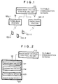
- Fig. 1 is a schematic diagram showing an example of the structure of a mobile communication system employing a communication channel assigning system according to an embodiment of the present invention.
- the mobile communication system comprises a radio base station controlling unit 110, a plurality of radio base stations 120 (120-1 and 120-2), and a plurality of mobile stations 130 (130-1, 130-2, and 130-3).
- the number of radio base stations 120 and the number of mobile stations 130 is not limited to those shown in Fig. 1.
- Each radio base station 120 is disposed in each known radio zone.
- Each radio base station 120 communicates with mobile stations 130 in the zone of the radio base station 120 using respective communication channels.
- communications channels having a plurality of frequency bandwidth are used as the same frequency band.
- Fig. 2 is a block diagram for explaining a communication channel assigning system according to a first embodiment of the present invention.
- Fig. 2 shows the structure of the radio base station 120 shown in Fig. 1.
- the radio base station 120 comprises a measuring means 121, an estimating means 122, and an assigning means 123.
- the measuring means 121 measures the interference power amount of each frequency band.
- the estimating means 122 estimates the transmission power amount required for the type of the service of a newly generated call.
- the assigning means 123 determines a frequency band with the minimum division loss corresponding to the interference power amount of each frequency band measured by the measuring means 121 and the transmission power amount estimated by the estimating means 122 and assigns the newly generated call to the determined frequency band.
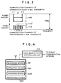
- Fig. 3 is a schematic diagram showing the state of use of communication channels upon occurrence of a new call.
- the horizontal axis and the vertical axis represent the frequency and power amount, respectively.
- a frequency band F1-F2 (5 MHz bandwidth) is used.
- the frequency band F1-F2 is divided into five frequency bands 1 to 5 (1 MHz bandwidth).
- communication channels of the narrow band (1 MHz bandwidth) correspond to the frequency bands 1 to 5.
- three communication channels of the narrow band are used.
- the communication channel of the intermediate band (5 MHz bandwidth) corresponds to all of the region of the frequency bands 1 to 5.
- all the region of the frequency bands 1 to 5 is referred to as a frequency band 6.
- two communication channels of the intermediate band are used.
- an interference power amount I3 of the frequency band 3 is obtained by adding an interference power amount In3 of a communication channel of the frequency band 3 of the narrow band and an interference power amount Im6 of a communication channel of the frequency band 6 of the intermediate band as expressed by the following formula (1).
- I3 In3 + Im6
- the estimating means 122 estimates the transmission power amount required for the type of the service of the generated call.
- the assigning means 123 determines a frequency band with the minimum division loss corresponding to the interference power amount measured by the measuring means 121 and the transmission power amount estimated by the estimating means 122 and assigns the newly generated call to the determined frequency band.
- the assigning means 123 obtains a temporary interference power amount of a communication channel in the case that the generated call is assigned to the frequency band 3.
- the temporary interference power amount of the frequency band 3 to which the generated call is assigned becomes I3 + In3 + .
- the temporary interference power amount I3 + In3 + is compared with the maximum interference power amount IMAX of the system.
- the assigning means 123 determines that the generated call can be assigned to the frequency band 3 and assigns the generated call to the frequency band 3.
- the interference power amounts In3 and In6 may be based on SIR (Signal Interference Ratio) of each frequency bandwidth.
- the case that a generated call is assigned to a channel of the narrow bandwidth (1 MHz) or a channel of the intermediate bandwidth (5 MHz) was described.
- the present invention can be applied to the case that a call is assigned to a channel of the wide bandwidth (20 MHz) as well as a channel of the narrow bandwidth (1 MHz) or a channel of the intermediate bandwidth (5 MHz).
- Fig. 4 is a block diagram for explaining a communication channel assigning system according to a second embodiment of the present invention.
- Fig. 4 shows the structure of a radio base station 220.
- the second embodiment features the radio base station 220 that is disposed instead of the radio base station shown in Fig. 1.
- the radio base station 220 comprises a measuring means 221, an estimating means 222, and an assigning means 223.
- the measuring means 221 measures the interference power amount of each frequency band for a newly generated call.
- the estimating means 222 estimates the transmission power amount necessary for the type of the service of the newly generated call.
- the assigning means 223 simulates the interference power amount of each frequency band in the case that each existing call is handed over to another frequency band and obtains the resultant simulation information, hands over each existing call corresponding to the interference power amount of each frequency band measured by the measuring means 221, the transmission power amount estimated by the estimating means 222, and the simulation information, determines the frequency band with the minimum division loss for the newly generated call, and assigns the newly generated call to the determined frequency band.
- Fig. 5A is a schematic diagram showing the used state of communication channels upon occurrence of a new call.
- the horizontal axis and vertical axis show the frequency and power amount, respectively.
- a frequency band F1-F2 (5 MHz bandwidth) is divided into five frequency bands 1 to 5 (1 MHz bandwidth).
- communication channels of the narrow band (1 MHz bandwidth) correspond to frequency bands 1 to 5.
- the frequency band 1 three communication channels of the narrow band are used.
- two communication channels of the narrow band are used.
- the frequency band 3 four communication channels of the narrow band are used.
- Communication channels of the intermediate band (5 MHz bandwidth) correspond to a frequency band 6 that is the whole region of the frequency bands 1 to 5.
- two communication channels of the intermediate band are used.
- the measuring means 221 of the radio base station 220 measures the interference power amount of each of the frequency bands 1 to 5.
- the interference power amounts I1 to I5 of the frequency bands 1 to 5 are obtained by adding the interference power amounts In1 to In5 of communication channels of the frequency bands 1 to 5 of the narrow band and the interference power amount Im6 of a communication channel of the frequency band 6 of the intermediate band as expressed by Formula (3).
- the estimating means 22 estimates the power amount necessary for the type of the service of the newly generated call.
- the assigning means 223 hands over each existing call corresponding to the interference power amount of each frequency band measured by the measuring means 221, the transmission power amount estimated by the estimating means 222, and simulation information of which each existing call is handed over from an original frequency band to another frequency band, obtains hand-over source and destination of each existing call and the temporary interference power amount of a communication channel of each frequency band to which the newly generated call is assigned, and assigns the newly generated call to a frequency band with less than the maximum interference power amount IMAX.
- the assigning means 223 obtains the temporary interference power amounts I1 + Im6 + , I2 + Im6 + , I3 + Im6 + , I4 + Im6 + , and I5 + Im6 + of the frequency bands 1 to 5 to which the newly generated call is temporarily assigned in the case that each existing call is not handed over.
- the temporary interference power amounts are compared with the maximum interference power amount IMAX of the system.
- the compared results are expressed by Formula (4).
- the assigning means 223 performs a simulation for handing over each existing call from the original frequency band to another frequency band and obtains simulation information of which one existing call in the frequency band 3 is temporarily handed over to the frequency band 2.
- the temporary interference power amounts of the frequency bands corresponding to the simulation information are compared with the maximum interference power amount IMAX of the system, the results expressed by Formula (5) are obtained.
- the assigning means 224 determines that the newly generated call can be assigned to the frequency band 6 in the condition that one existing call in the frequency band 3 is handed over to the frequency band 2.
- the assigning means 224 hands over one existing call in the frequency band 3 to the frequency band 2 and assigns the newly generated call to the frequency band 6 as shown in Fig. 5B.
- the case that a generated call is assigned to a channel of the narrow bandwidth (1 MHz) or a channel of the intermediate bandwidth (5 MHz) was described.
- the present invention can be applied to the case that a call is assigned to a channel of the wide bandwidth (20 MHz) as well as a channel of the narrow bandwidth (1 MHz) or a channel of the intermediate bandwidth (5 MHz).
- Fig. 6 is a block diagram for explaining a communication channel assigning system according to a third embodiment of the present invention.
- Fig. 6 shows principal portions of a mobile communication system for the communication channel assigning system.
- the third embodiment features a radio base station 320 and a radio base station controlling unit 310 disposed instead of the radio base station 120 and the radio base station controlling unit 110 shown in Fig. 1, respectively.
- the radio base station 320 comprises a measuring means 321, an estimating means 322, and an estimated result informing means 323.
- the estimated result informing means 323 informs the radio base station controlling unit 310 of a transmission power amount estimated by the estimating means 322.
- the radio base station controlling unit 310 comprises an assigning means 311.
- the structures and operations of the measuring means 321, the estimating means 322, and the assigning means 311 according to the third embodiment are the same as those of the measuring means 121, the estimating means 122, and the assigning means 123 according to the first embodiment.
- the structures and operations of the measuring means 321, the estimating means 322, and the assigning means 311 according to the third embodiment are the same as those of the measuring means 221, the estimating means 222, and the assigning means 223 according to the second embodiment.
- the structure of the third embodiment shown in Fig. 6 since only the radio base station controlling unit 310 assigns newly generated calls to relevant frequency bands corresponding to estimated results of a plurality of base stations 320, interference of frequencies among a plurality of cells can be suppressed.
- Fig. 7 is a block diagram for explaining a communication channel assigning system according to a forth embodiment of the present invention.
- Fig. 7 shows the principal portion of a mobile communication system for the communication channel assigning system.
- the fourth embodiment features a radio base station 420 and a radio bases station 410 disposed instead of the radio base station 120 and the radio base station controlling unit 110 shown in Fig. 1.
- the radio base station 420 comprises a measuring means 421 and a measured result informing means 422.
- the measured result informing means 422 informs the radio base station controlling unit 410 of each interference power amount measured by the measuring means 421.
- the radio base station controlling unit 410 comprises an estimating means 411 and an assigning means 412.
- the structures and operations of the measuring means 421, the estimating means 411, and the assigning means 412 according to the fourth embodiment are the same as those of the measuring means 121, the estimating means 122, and the assigning means 123 according to the first embodiment.
- the structures and operations of the measuring means 421, the estimating means 411, and the assigning means 412 according to the fourth embodiment are the same as those of the measuring means 221, the estimating means 222, and the assigning means 223 according to the second embodiment.
- the radio base station controlling unit 410 obtains the interference power amounts measured by the radio base station 420 of each area cell.
- the radio base station controlling unit 410 estimates proper frequency bands and assigns newly generated calls to the estimated frequency bands.
- the interference of frequencies can be suppressed.
- the communication quality and QOS(Quality of service) can be improved.
- communication channels of different frequency bands can be effectively used.
Landscapes
- Engineering & Computer Science (AREA)
- Computer Networks & Wireless Communication (AREA)
- Signal Processing (AREA)
- Mobile Radio Communication Systems (AREA)
Applications Claiming Priority (3)
| Application Number | Priority Date | Filing Date | Title |
|---|---|---|---|
| JP23710997 | 1997-09-02 | ||
| JP237109/97 | 1997-09-02 | ||
| JP9237109A JP3028940B2 (ja) | 1997-09-02 | 1997-09-02 | 通信チャネル割り当て方式 |
Publications (3)
| Publication Number | Publication Date |
|---|---|
| EP0901243A2 true EP0901243A2 (de) | 1999-03-10 |
| EP0901243A3 EP0901243A3 (de) | 2003-04-16 |
| EP0901243B1 EP0901243B1 (de) | 2006-10-18 |
Family
ID=17010554
Family Applications (1)
| Application Number | Title | Priority Date | Filing Date |
|---|---|---|---|
| EP19980250305 Expired - Lifetime EP0901243B1 (de) | 1997-09-02 | 1998-08-27 | Kommunikationskanal Zuteilungsverfahren |
Country Status (7)
| Country | Link |
|---|---|
| US (1) | US6131035A (de) |
| EP (1) | EP0901243B1 (de) |
| JP (1) | JP3028940B2 (de) |
| KR (1) | KR100291727B1 (de) |
| CN (1) | CN1092009C (de) |
| BR (1) | BR9803534A (de) |
| DE (1) | DE69836181T2 (de) |
Cited By (5)
| Publication number | Priority date | Publication date | Assignee | Title |
|---|---|---|---|---|
| WO2001022617A3 (en) * | 1999-09-17 | 2001-10-18 | Nokia Networks Oy | Power estimation method |
| EP1565018A3 (de) * | 2004-02-13 | 2010-11-10 | Fujitsu Limited | Basisstationssteuerungsgerät und übereinstimmendes Frequenzzuteilungsverfahren |
| EP2001248A4 (de) * | 2006-03-29 | 2012-04-18 | Fujitsu Ltd | Kommunikationsvorrichung und endgerät |
| CN102904700A (zh) * | 2008-05-29 | 2013-01-30 | 株式会社Ntt都科摩 | 无线资源选择方法、移动台以及无线基站 |
| WO2014010275A3 (en) * | 2012-07-09 | 2014-03-20 | Kabushiki Kaisha Toshiba | Wireless communication method, system and apparatus |
Families Citing this family (11)
| Publication number | Priority date | Publication date | Assignee | Title |
|---|---|---|---|---|
| US6119010A (en) * | 1998-10-13 | 2000-09-12 | Motorola, Inc. | Method and apparatus for adjusting channel powers in a wireless communication system based on a predicted mobile location |
| FI108696B (fi) * | 1998-10-21 | 2002-02-28 | Nokia Corp | Menetelmä ja järjestelmä matkaviestintään |
| US6546252B1 (en) * | 1998-12-18 | 2003-04-08 | Telefonaktiebolaget Lm Ericsson (Publ) | System and method for estimating interfrequency measurements used for radio network function |
| US6721568B1 (en) * | 1999-11-10 | 2004-04-13 | Telefonaktiebolaget Lm Ericsson (Publ) | Admission control in a mobile radio communications system |
| JP4171186B2 (ja) * | 2001-04-04 | 2008-10-22 | 富士通株式会社 | 移動通信システムにおけるチャネル設定方法 |
| JP3842666B2 (ja) * | 2002-02-20 | 2006-11-08 | 株式会社エヌ・ティ・ティ・ドコモ | 基地局及び通信方法 |
| US7945280B2 (en) | 2003-02-20 | 2011-05-17 | Fujitsu Limited | Radio channel control method and receiving apparatus |
| JPWO2004075438A1 (ja) | 2003-02-20 | 2006-06-01 | 富士通株式会社 | 無線チャネル制御方法及び受信装置 |
| KR101170446B1 (ko) | 2004-06-03 | 2012-08-07 | 조승호 | 저소비 전력형 무선 데이터 전송방법 |
| JP4806709B2 (ja) * | 2006-05-30 | 2011-11-02 | 株式会社日立製作所 | 移動通信システムの接続制御方法及び基地局装置 |
| CN114642052A (zh) * | 2019-11-06 | 2022-06-17 | 瑞典爱立信有限公司 | 将移动设备分配到无线电站点的频带 |
Family Cites Families (11)
| Publication number | Priority date | Publication date | Assignee | Title |
|---|---|---|---|---|
| JP3243544B2 (ja) * | 1993-07-06 | 2002-01-07 | 日立通信システム株式会社 | スペクトル拡散通信における干渉有無試験方法、通信チャネル設定方法およびスペクトル拡散通信方法 |
| JPH07107545A (ja) * | 1993-10-07 | 1995-04-21 | Nec Corp | セクタセル構成移動通信システム |
| JP2531457B2 (ja) * | 1993-11-15 | 1996-09-04 | 日本電気株式会社 | 移動通信システム |
| JP2734953B2 (ja) * | 1993-12-16 | 1998-04-02 | 日本電気株式会社 | Cdma受信装置 |
| GB2288517A (en) * | 1994-04-05 | 1995-10-18 | Roke Manor Research | Channel selection in a CDMA cellular mobile radio system |
| JPH07297753A (ja) * | 1994-04-28 | 1995-11-10 | Oki Electric Ind Co Ltd | フレーム送信タイミング制御方法 |
| JPH098769A (ja) * | 1995-06-23 | 1997-01-10 | Nippon Motorola Ltd | スペクトル拡散変調を用いた無線通信システム |
| JP3078216B2 (ja) * | 1995-12-13 | 2000-08-21 | 株式会社エヌ・ティ・ティ・ドコモ | 基地局選択方法 |
| JP2991232B2 (ja) * | 1996-03-08 | 1999-12-20 | 株式会社ワイ・アール・ピー移動通信基盤技術研究所 | 帯域分割形cdma方式および送受信装置 |
| JPH09327072A (ja) * | 1996-06-05 | 1997-12-16 | Hitachi Ltd | Cdma通信方法及びスペクトル拡散通信システム |
| JPH10126842A (ja) * | 1996-10-18 | 1998-05-15 | Matsushita Electric Ind Co Ltd | 移動通信システム |
-
1997
- 1997-09-02 JP JP9237109A patent/JP3028940B2/ja not_active Expired - Fee Related
-
1998
- 1998-08-27 DE DE1998636181 patent/DE69836181T2/de not_active Expired - Lifetime
- 1998-08-27 EP EP19980250305 patent/EP0901243B1/de not_active Expired - Lifetime
- 1998-09-01 KR KR1019980035866A patent/KR100291727B1/ko not_active Expired - Fee Related
- 1998-09-01 US US09/144,996 patent/US6131035A/en not_active Expired - Lifetime
- 1998-09-01 CN CN98117662A patent/CN1092009C/zh not_active Expired - Fee Related
- 1998-09-01 BR BR9803534A patent/BR9803534A/pt not_active IP Right Cessation
Cited By (8)
| Publication number | Priority date | Publication date | Assignee | Title |
|---|---|---|---|---|
| WO2001022617A3 (en) * | 1999-09-17 | 2001-10-18 | Nokia Networks Oy | Power estimation method |
| US6985700B1 (en) | 1999-09-17 | 2006-01-10 | Nokia Corporatiion | Power estimation method |
| EP1565018A3 (de) * | 2004-02-13 | 2010-11-10 | Fujitsu Limited | Basisstationssteuerungsgerät und übereinstimmendes Frequenzzuteilungsverfahren |
| EP2001248A4 (de) * | 2006-03-29 | 2012-04-18 | Fujitsu Ltd | Kommunikationsvorrichung und endgerät |
| US8265647B2 (en) | 2006-03-29 | 2012-09-11 | Fujitsu Limited | Communication terminal and device |
| CN102904700A (zh) * | 2008-05-29 | 2013-01-30 | 株式会社Ntt都科摩 | 无线资源选择方法、移动台以及无线基站 |
| CN102904700B (zh) * | 2008-05-29 | 2015-12-09 | 株式会社Ntt都科摩 | 无线资源选择方法、移动台以及无线基站 |
| WO2014010275A3 (en) * | 2012-07-09 | 2014-03-20 | Kabushiki Kaisha Toshiba | Wireless communication method, system and apparatus |
Also Published As
| Publication number | Publication date |
|---|---|
| KR100291727B1 (ko) | 2001-07-12 |
| CN1092009C (zh) | 2002-10-02 |
| JP3028940B2 (ja) | 2000-04-04 |
| EP0901243A3 (de) | 2003-04-16 |
| CN1212590A (zh) | 1999-03-31 |
| KR19990029416A (ko) | 1999-04-26 |
| BR9803534A (pt) | 1999-11-03 |
| US6131035A (en) | 2000-10-10 |
| EP0901243B1 (de) | 2006-10-18 |
| DE69836181T2 (de) | 2007-08-23 |
| JPH1188940A (ja) | 1999-03-30 |
| DE69836181D1 (de) | 2006-11-30 |
Similar Documents
| Publication | Publication Date | Title |
|---|---|---|
| EP0901243B1 (de) | Kommunikationskanal Zuteilungsverfahren | |
| US5410737A (en) | Frequency agile sharing technology (FAST) for a personal communications service system | |
| EP1075767B1 (de) | System und verfahren zur erhöhung der cdma leistungsfähigkeit durch frequenzzuordnung | |
| KR100470374B1 (ko) | 다중초대역무선통신시스템 | |
| AU759370B2 (en) | Method and apparatus for performing handoff in a CDMA system through the use of repeaters | |
| US8787309B1 (en) | Seamless mobility in wireless networks | |
| EP0546720B1 (de) | Verringerte Interferenzstörungen durch versetzte Frequenzaufteilung in zellularen Kommunikationssystemen | |
| EP1452062B1 (de) | Verfahren, system und mobiles endgerät zur optimalen spektrumsverwendung in mobilfunksystemen | |
| US20030129982A1 (en) | Soft handoff in a wireless communication system | |
| EP1204289A3 (de) | Zeitsprung von Kontrollkanal und/oder Nutzkanal in einem zellularen Funkkommunikationssystem mit Frequenzsprung | |
| US6421370B1 (en) | Spectrum spreading system | |
| EP0955781A2 (de) | Verfahren und System zur Feststellung der Priorität für Weiterreichen basiert auf relativer Änderung der Signalintensität | |
| WO1999059362A1 (en) | Radio communication system, and method and apparatus for frequency allocation | |
| KR20000022979A (ko) | 파일럿 커버리지 추정 방법 및 장치 | |
| KR19990070745A (ko) | 다중 주파수 채널 확산대역 이동통신시스템에서의 채널 할당 방법 | |
| WO1997008909A1 (en) | A method of levelling a traffic load of a base station in a cellular radio system, and a cellular radio system | |
| US6205132B1 (en) | Method for accessing a cell using two pilot channels in a CDMA communication system of an asynchronous or quasi-synchronous mode | |
| JPH11510332A (ja) | セルラ無線システムにおける同一チャネル干渉の低減方法および低減装置 | |
| US7627319B2 (en) | Mobile terminal | |
| RU2335088C2 (ru) | Синхронная маршрутизация между пикосетями | |
| US7702285B2 (en) | System and method for determining mobile communication system carrier frequency propagation characteristics | |
| JP2991232B2 (ja) | 帯域分割形cdma方式および送受信装置 | |
| JP2002159061A (ja) | Cdma移動通信システム | |
| US20040151139A1 (en) | Method and arrangement for generating pilot beacons in wireless communication systems | |
| EP1310122B1 (de) | Lastverteilung in einem zellularen funkkommunikationssystem |
Legal Events
| Date | Code | Title | Description |
|---|---|---|---|
| PUAI | Public reference made under article 153(3) epc to a published international application that has entered the european phase |
Free format text: ORIGINAL CODE: 0009012 |
|
| AK | Designated contracting states |
Kind code of ref document: A2 Designated state(s): AT BE CH CY DE DK ES FI FR GB GR IE IT LI LU MC NL PT SE |
|
| AX | Request for extension of the european patent |
Free format text: AL;LT;LV;MK;RO;SI |
|
| PUAL | Search report despatched |
Free format text: ORIGINAL CODE: 0009013 |
|
| AK | Designated contracting states |
Designated state(s): AT BE CH CY DE DK ES FI FR GB GR IE IT LI LU MC NL PT SE |
|
| AX | Request for extension of the european patent |
Extension state: AL LT LV MK RO SI |
|
| RIC1 | Information provided on ipc code assigned before grant |
Ipc: 7H 04Q 7/38 B Ipc: 7H 04B 7/005 B Ipc: 7H 04B 7/26 A |
|
| 17P | Request for examination filed |
Effective date: 20030328 |
|
| AKX | Designation fees paid |
Designated state(s): DE GB |
|
| GRAP | Despatch of communication of intention to grant a patent |
Free format text: ORIGINAL CODE: EPIDOSNIGR1 |
|
| GRAS | Grant fee paid |
Free format text: ORIGINAL CODE: EPIDOSNIGR3 |
|
| GRAA | (expected) grant |
Free format text: ORIGINAL CODE: 0009210 |
|
| AK | Designated contracting states |
Kind code of ref document: B1 Designated state(s): DE GB |
|
| REG | Reference to a national code |
Ref country code: GB Ref legal event code: FG4D |
|
| REF | Corresponds to: |
Ref document number: 69836181 Country of ref document: DE Date of ref document: 20061130 Kind code of ref document: P |
|
| PLBE | No opposition filed within time limit |
Free format text: ORIGINAL CODE: 0009261 |
|
| STAA | Information on the status of an ep patent application or granted ep patent |
Free format text: STATUS: NO OPPOSITION FILED WITHIN TIME LIMIT |
|
| 26N | No opposition filed |
Effective date: 20070719 |
|
| PGFP | Annual fee paid to national office [announced via postgrant information from national office to epo] |
Ref country code: DE Payment date: 20160823 Year of fee payment: 19 Ref country code: GB Payment date: 20160824 Year of fee payment: 19 |
|
| REG | Reference to a national code |
Ref country code: DE Ref legal event code: R119 Ref document number: 69836181 Country of ref document: DE |
|
| GBPC | Gb: european patent ceased through non-payment of renewal fee |
Effective date: 20170827 |
|
| PG25 | Lapsed in a contracting state [announced via postgrant information from national office to epo] |
Ref country code: DE Free format text: LAPSE BECAUSE OF NON-PAYMENT OF DUE FEES Effective date: 20180301 Ref country code: GB Free format text: LAPSE BECAUSE OF NON-PAYMENT OF DUE FEES Effective date: 20170827 |