EP0901178B1 - Non-aqueous electrolyte cell with spirally wound electrodes - Google Patents
Non-aqueous electrolyte cell with spirally wound electrodes Download PDFInfo
- Publication number
- EP0901178B1 EP0901178B1 EP97306289A EP97306289A EP0901178B1 EP 0901178 B1 EP0901178 B1 EP 0901178B1 EP 97306289 A EP97306289 A EP 97306289A EP 97306289 A EP97306289 A EP 97306289A EP 0901178 B1 EP0901178 B1 EP 0901178B1
- Authority
- EP
- European Patent Office
- Prior art keywords
- positive electrode
- negative electrode
- electrode
- insulating tape
- current collector
- Prior art date
- Legal status (The legal status is an assumption and is not a legal conclusion. Google has not performed a legal analysis and makes no representation as to the accuracy of the status listed.)
- Expired - Lifetime
Links
Images

Classifications
-
- H—ELECTRICITY
- H01—ELECTRIC ELEMENTS
- H01M—PROCESSES OR MEANS, e.g. BATTERIES, FOR THE DIRECT CONVERSION OF CHEMICAL ENERGY INTO ELECTRICAL ENERGY
- H01M10/00—Secondary cells; Manufacture thereof
- H01M10/04—Construction or manufacture in general
- H01M10/0431—Cells with wound or folded electrodes
-
- H—ELECTRICITY
- H01—ELECTRIC ELEMENTS
- H01M—PROCESSES OR MEANS, e.g. BATTERIES, FOR THE DIRECT CONVERSION OF CHEMICAL ENERGY INTO ELECTRICAL ENERGY
- H01M50/00—Constructional details or processes of manufacture of the non-active parts of electrochemical cells other than fuel cells, e.g. hybrid cells
- H01M50/40—Separators; Membranes; Diaphragms; Spacing elements inside cells
-
- H—ELECTRICITY
- H01—ELECTRIC ELEMENTS
- H01M—PROCESSES OR MEANS, e.g. BATTERIES, FOR THE DIRECT CONVERSION OF CHEMICAL ENERGY INTO ELECTRICAL ENERGY
- H01M10/00—Secondary cells; Manufacture thereof
- H01M10/05—Accumulators with non-aqueous electrolyte
-
- Y—GENERAL TAGGING OF NEW TECHNOLOGICAL DEVELOPMENTS; GENERAL TAGGING OF CROSS-SECTIONAL TECHNOLOGIES SPANNING OVER SEVERAL SECTIONS OF THE IPC; TECHNICAL SUBJECTS COVERED BY FORMER USPC CROSS-REFERENCE ART COLLECTIONS [XRACs] AND DIGESTS
- Y02—TECHNOLOGIES OR APPLICATIONS FOR MITIGATION OR ADAPTATION AGAINST CLIMATE CHANGE
- Y02E—REDUCTION OF GREENHOUSE GAS [GHG] EMISSIONS, RELATED TO ENERGY GENERATION, TRANSMISSION OR DISTRIBUTION
- Y02E60/00—Enabling technologies; Technologies with a potential or indirect contribution to GHG emissions mitigation
- Y02E60/10—Energy storage using batteries
-
- Y—GENERAL TAGGING OF NEW TECHNOLOGICAL DEVELOPMENTS; GENERAL TAGGING OF CROSS-SECTIONAL TECHNOLOGIES SPANNING OVER SEVERAL SECTIONS OF THE IPC; TECHNICAL SUBJECTS COVERED BY FORMER USPC CROSS-REFERENCE ART COLLECTIONS [XRACs] AND DIGESTS
- Y02—TECHNOLOGIES OR APPLICATIONS FOR MITIGATION OR ADAPTATION AGAINST CLIMATE CHANGE
- Y02P—CLIMATE CHANGE MITIGATION TECHNOLOGIES IN THE PRODUCTION OR PROCESSING OF GOODS
- Y02P70/00—Climate change mitigation technologies in the production process for final industrial or consumer products
- Y02P70/50—Manufacturing or production processes characterised by the final manufactured product
Definitions
- the present invention relates to a non-aqueous electrolyte cell including an electrode assembly comprising a strip of negative electrode of light metal as active material, and a strip of positive electrode which are separated from each other by a separator and wound in a spiral, and a specific non-aqueous (organic) electrolyte which is stable with respect to the light metal.
- Non-aqueous electrolyte cells including light metal such as lithium as active anode material and oxide or the like as active cathode material have various advantages over other primary cells such as having high voltage, high energy density with low self-discharge and extremely long storage life, and the range of their applications has been increased as used particularly in advanced electronic appliances.
- a typical type of such non-aqueous electrolyte cells has an electrode assembly comprising a strip of negative electrode and a strip of positive electrode which are separated by a separator and wound in a spiral.
- an anode current collector 8 is connected to the negative electrode 3 close to a point opposite to a winding end 3a of the negative electrode 3.
- the electrode assembly is wound into a spiral with its negative electrode 3 located outside the positive electrode.
- the outermost round of the negative electrode 3 thus has the positive electrode opposed thereto only on its inner side, separated with the separator.
- the active material of the negative electrode 3 in its outermost round which reacts with the positive electrode only on one side is electrochemically consumed about a half as compared with other inner rounds of the negative electrode 3 where the positive electrode oppose to the negative electrode at both sides.
- unreacted active anode material of light metal 3b still remains even in the final discharge state as shown in Fig. 6.
- the unreacted active light metal 3b remains more in amount between the anode current collector 8 and the winding end 3a of the negative electrode 3, partly being electrically connected with the anode current collector 8.
- the applicant has proposed an improved non-aqueous electrolyte cell capable of overcoming above described disadvantages even when the unreacted active light metal 3b remains in a used battery as disclosed in Japanese Published Unexamined Patent Application No. H5-13089.
- An arrangement of such cell is illustrated in Fig. 5.
- a strip of positive electrode 2 made of manganese dioxide as active cathode material and a strip of negative electrode 3 made of a lithium foil are separated from each other by a separator 4 and wound in a spiral so that the negative electrode 3 comes to an outer side of the positive electrode 2, thus constituting an electrode assembly 1 which is accommodated in a cell housing 9.
- a winding end 3a of the negative electrode 3 is positioned within an angular range of 180 degrees extending from a winding end 2a of the positive electrode 2 in a direction opposite to a winding direction.
- an anode current collector 8 is provided to an inner round of the negative electrode 3 being shifted closer to the spiral core than a point just opposite to the end 3a of the negative electrode 3.
- the end 2a of the positive electrode 2 is covered with an insulating tape 10 such as a piece of glass tape. This prevents any burr of the positive electrode 2 produced in cutting the end 2a from piercing the separator 4 to cause leakage.
- active anode material of light metal 3b which remains unreacted mostly in the outermost round of the negative electrode 3 in the final discharge state is parted from the anode current collector 8 to prevent electrical connection there between.
- An end portion 2b of the positive electrode 2 between its end 2a and the end 3a of the negative electrode 3 is opposed to the negative electrode 3 only at its inner side, with which it reacts intensively, causing velocity controlling reaction in the negative electrode 3 opposing to the end portion 2b of the positive electrode 2.
- the velocity controlling reaction is further accelerated.
- the non-aqueous electrolyte cell of the above described prior art arrangement is capable of avoiding a short-circuit by preventing an active anode material from being deposited on the positive electrode 2 by electrolysis even when the cell is forcibly discharged in the final discharge state.
- the end portion 2b of the positive electrode 2 is specifically set to be as relatively short as 2 to 10 mm.
- the electrode assembly 1 is produced on a large scale by winding the positive electrode 2 and the negative electrode 3 in strips separated by the separator 4 and superposed on each other in a spiral with an automatic winder machine. It is thus necessary to determine the overall lengths of the positive and negative electrodes 2, 3 as well as mechanical precision of the automatic winder machine with extremely high accuracy in order to fabricate an electrode assembly 1 having a positive electrode end portion 2b of appropriate length.
- a non-aqueous electrolyte cell is characterized in that an anode current collector is disposed at an inner side of the negative electrode opposing to a winding end of the positive electrode, and that an insulating tape for protection of the end of the positive electrode is provided to have an outer portion extending continuously or intermittently on the outer side of the positive electrode longer in a direction toward the spiral core than an inner portion thereof covering the inner side of the positive electrode.
- the insulating tape for covering the end of the positive electrode extends from the end to the predetermined location along the outer side of the positive electrode.
- a part of the negative electrode opposing to the positive electrode covered by the insulating tape is physically separated due to the velocity controlling reaction which is partly accelerated therein.
- the anode current collector is disposed at an inner side with respect to the end of the positive electrode, thus causing the above said separation to occur in the vicinity of the anode current collector in the negative electrode, which ensures a complete separation of the outermost round of the negative electrode where unreacted anode material is remained in great amount.
- the electrodeposition of the anode material on the positive electrode will be prevented thus eliminating any troubles caused by a short-circuit between the positive and negative electrodes even when the electrode assembly having a mal-posed negative electrode extending up to or further than the end of the positive electrode is produced.
- This effect can be obtained with the use of a common insulating tape tailored to a desired shape with less cost.
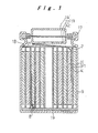
- Fig. 1 is a longitudinal cross sectional view of a non-aqueous electrolyte cell according to an embodiment of the present invention
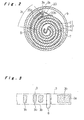
- Fig. 2 is a transverse cross sectional view thereof. Parts same or similar to those previously described with respect to Fig. 5 are denoted by the same reference numerals, and the description thereof will be omitted.
- a cylindrical cell housing 9 made of iron has a bottom as a negative terminal.
- An electrode assembly 1 wound in a spiral is submerged in a specific organic electrolyte (not shown) which is stable with respect to the light metal constituting active anode material in the cell housing 9.
- the upper opening of the cell housing 9 is hermetically sealed with a sealing member 11 caulked and fixed thereto via a packing 17.
- the sealing member 11 comprises a lower cover 12, a filmy valve 13, and an upper cover 14.
- the electrode assembly 1 is fabricated by winding a lamination of a strip of positive electrode 2 made of a metal mesh filled with manganese dioxide as active cathode material, a separator 4 made of a porous polypropylene film, and a strip of negative electrode 3 made of a lithium foil so that the negative electrode 3 is disposed outside the positive electrode 2.
- the electrode assembly 1 further includes a cathode current collector 7 provided to a part of the positive electrode 2 and an anode current collector 8 disposed in inner circles of the negative electrode 3 in the second round from the outermost periphery thereof.
- the cathode current collector 7 is drawn upwardly from the positive electrode 2 through an insulating ring 18 toward the bottom of the lower cover 12 and joined thereto by resistance welding as shown in Fig. 1.
- the anode current collector 8 is drawn downwardly from the negative electrode 3 through an insulating plate 19, folded on the lower side of the electrode assembly 1 under the insulating plate 19, and joined by resistance welding to the bottom surface of the cell housing 9.
- Each of the cathode current collector 7 and the anode current collector 8 has two pieces of adhesive tape bonded on both sides thereof, though not shown.
- the positive electrode 2, the negative electrode 3 , and the anode current collector 8 are 0.45 mm, 0.16 mm, and 0.1 mm in thickness, respectively.
- the positive electrode 2 is fabricated by filling the metal mesh with slurryed manganese dioxide as active cathode material and drying it, and thus a burr is inevitably formed at its winding end 2a when trimmed.
- the end 2a of the positive electrode 2 is normally covered at both sides with a piece of insulating tape 20 such as glass or polypropylene tape.
- the insulating tape 20 in this embodiment is provided with its outer portion 20a which covers the outer side of the positive electrode 2 extending longer than its inner portion 20b covering the inner side of the same.
- the outer portion 20a covering the outer side of the positive electrode 2 is set to have a length extending from the end 2a of the positive electrode 2 to a point substantially opposing to the anode current collector 8.
- the above described non-aqueous electrolyte cell is fabricated in a manner described below.
- the positive and negative electrodes 2, 3 separated by the separator 4 are wound in a spiral, with the respective current collectors 7, 8 fixed at their corresponding positions with an automatic winder machine to build the electrode assembly 1 shown in Fig. 2.
- the electrode assembly 1 is accommodated in the cell housing 9 which is then filled with an organic electrolyte.
- the sealing member 11 is mounted to an inwardly projecting annular support 21 of the cell housing 9 and caulked with the packing 17 thereto by folding the edge of the cell housing 9 inwardly. The opening of the cell housing 9 is thereby hermetically sealed with the sealing member 11 to complete the cell.
- the end 3a of the negative electrode 3 is wound to locate within a range of 180 degrees from the end 2a of the positive electrode 2 in a reverse direction of winding, and the anode current collector 8 is mounted in inner circles of the negative electrode 3 opposing to the end 3a thereof at its inner side but slightly shifted in the direction toward the spiral core. Since the lamination of the positive electrode 2, the separator 4, and the negative electrode 3 is wound by the automatic winder machine, the end 3a of the negative electrode 3 in the electrode assembly 1 may sometimes extend in the winding direction further than the end 2a of the positive electrode 2 as shown in Fig. 2, due to various reasons such as variation in initial setting at the spiral core.
- the cell of this embodiment can obviate the above mentioned problem as hereinafter described, with the help of the insulating tape accurately bonded to the end 2a of the positive electrode 2.
- the end portion 2c covered by the insulating tape 20 of the positive electrode 2 between its end 2a and a position opposing to the anode current collector 8 is electrically separated by the outer portion 20a of the insulating tape 20 from the outermost round of the negative electrode 3, so as to cause the positive electrode 2 to face with the negative electrode 3 only at inner side thereof.
- the covered end portion 2c of the positive electrode 2 to react intensively with the negative electrode 3 at its inner side when the cell in its final discharge state is forcibly discharged. Accordingly, the velocity controlling reaction is partly enhanced in the negative electrode 3 at the inner side of the covered end portion 2c of the positive electrode 2 between the vicinity of the anode current collector 8 and a point opposite to the end 2a of the positive electrode 2 which corresponds to the length of the outer portion 20a of the insulating tape 20.
- the active anode material 3b is thereby consumed to be electrically disconnected from the anode current collector 8 as shown in Fig. 3.
- the negative electrode 3 is physically separated at a point slightly distanced from the anode current collector 8 in the winding direction to isolate the component of active light metal material 3b remained unreacted in the outermost round of the negative electrode 3 from the anode current collector 8. Therefore, it is prevented that the remaining active material of light metal 3b is deposited on the positive electrode 2 by electrolysis, eliminating any troubles caused by a short-circuit between the positive electrode 2 and the negative electrode 3.
- the insulating tape 10 provided in the conventional non-aqueous electrolyte cell is rather short in length for covering only the tip of the end 2a of the positive electrode 2 as shown in Fig. 5 in such a way that it covers the end 2a from both sides with substantially the same length.
- the insulating tape 20 is of the same material as of the insulating tape 10 but only different in length and position, thus not being an additional member devised by the present invention. Instead of providing the insulating tape 20 as shown in Fig.
- another piece of tape may be provided somewhere between the end 2a and a point opposite to the anode current collector 8 in addition to the conventional tape covering only the tip of the positive electrode end 2a, by which the same effect as of this embodiment will be achieved.
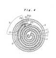
- Fig. 4 is a transverse cross sectional view of a non-aqueous electrolyte cell showing another embodiment of the present invention, in which parts same or similar to those previously described with respect to Fig. 2 are denoted by the same reference numerals, and the description thereof will be omitted.
- the insulating tape 20 of this embodiment is short in length for covering the end 2a of the positive electrode 2 from both sides like the one shown in Fig. 5, and an auxiliary insulating tape 22 of which material is identical to that of the insulating tape 20 is additionally provided on the inner side of the outermost round of the negative electrode 3 close to its end 3a.
- the auxiliary insulating tape 22 is sandwiched between the inner side of the negative electrode 3 close to its end 3a and the outer side of the positive electrode 2 close to its end 2a, the part of the positive electrode 2 where the auxiliary insulating tape 22 electrically isolates it from the outermost round of the negative electrode 3 opposes to the negative electrode 3 only at the inner side thereof. Accordingly, when the cell in its final discharge state is forcibly discharged, a part of the negative electrode 3 slightly off the anode current collector 8 in the winding direction is separated due to the accelerated velocity controlling reaction therein. It is thus avoided that the remaining anode material is electrodeposited on the positive electrode 2, preventing any troubles caused by a short-circuit between the positive electrode 2 and the negative electrode 3.
- the auxiliary insulating tape 22 is bonded within a range of tape bonding portion 3c in the outermost round of the negative electrode 3 between the end 3a and a point opposing to the anode current collector 8 but slightly forwarded in the winding direction.
- the auxiliary insulating tape 22 may be either bonded to the whole range 3c of tape bonding portion at the inner side of the negative electrode 3 or at least at one point within the range as shown in Fig. 4.
- the insulating tape for covering the end of the positive electrode extends from the end to the predetermined location along the outer side of the positive electrode.
- a part of the negative electrode opposing to the positive electrode covered by the insulating tape is physically separated due to the velocity controlling reaction which is partly accelerated therein.
- the anode current collector is disposed at an inner side with respect to the end of the positive electrode, thus causing the above said separation to occur in the vicinity of the anode current collector in the negative electrode, which ensures a complete separation of the outermost round of the negative electrode where unreacted anode material remains in great amount from the anode current collector. Accordingly, the electrodeposition of the anode material on the positive electrode will be prevented thus eliminating any troubles caused by a short-circuit between the positive and negative electrodes, even when the electrode assembly having a mal-posed negative electrode extending up to or further than the end of the positive electrode is produced. This effect can be obtained with the use of a common insulating tape tailored to a desired shape with less cost.
- the anode current collector is preferably disposed in the negative electrode closer to the spiral core than the point opposing to the end of the positive electrode, and the insulating tape is preferably provided on the outer side of the positive electrode extending from the end to substantially the point opposing to the anode current collector. This will ensure that the negative electrode is separated at a point slightly off the anode current collector in the winding direction, eliminating the remaining unreacted anode material electrically connected to the anode current collector and enhancing safety of the cell.
- the auxiliary insulating tape is provided to at least a part within the range on the inner side of the outermost round of the negative electrode from the end to the point opposing to the anode current collector.
- the corresponding part of the positive electrode covered with the auxiliary insulating tape is electrically isolated from the outermost round of the negative electrode and opposed to the negative electrode only at its inner side.
- the negative electrode is physically separated at a point slightly off the anode current collector in the winding direction due to the velocity controlling reaction partly accelerated therein, thus avoiding the electrodeposition of the anode material on the positive electrode, preventing any troubles caused by a short-circuit between the positive and negative electrodes.
Description
- The present invention relates to a non-aqueous electrolyte cell including an electrode assembly comprising a strip of negative electrode of light metal as active material, and a strip of positive electrode which are separated from each other by a separator and wound in a spiral, and a specific non-aqueous (organic) electrolyte which is stable with respect to the light metal.
- Non-aqueous electrolyte cells including light metal such as lithium as active anode material and oxide or the like as active cathode material have various advantages over other primary cells such as having high voltage, high energy density with low self-discharge and extremely long storage life, and the range of their applications has been increased as used particularly in advanced electronic appliances.
- A typical type of such non-aqueous electrolyte cells has an electrode assembly comprising a strip of negative electrode and a strip of positive electrode which are separated by a separator and wound in a spiral. As shown in Fig. 6 which illustrates a development of the negative electrode in a final discharge state, an anode
current collector 8 is connected to thenegative electrode 3 close to a point opposite to awinding end 3a of thenegative electrode 3. The electrode assembly is wound into a spiral with itsnegative electrode 3 located outside the positive electrode. The outermost round of thenegative electrode 3 thus has the positive electrode opposed thereto only on its inner side, separated with the separator. Accordingly, the active material of thenegative electrode 3 in its outermost round which reacts with the positive electrode only on one side is electrochemically consumed about a half as compared with other inner rounds of thenegative electrode 3 where the positive electrode oppose to the negative electrode at both sides. As a result, unreacted active anode material oflight metal 3b still remains even in the final discharge state as shown in Fig. 6. Particularly, the unreactedactive light metal 3b remains more in amount between the anodecurrent collector 8 and thewinding end 3a of thenegative electrode 3, partly being electrically connected with the anodecurrent collector 8. - When one of a plurality of cells connected in series in their final discharge states is replaced with a new one, the capacity of each cell is unbalanced and the cells are forced to discharge. In that case, since the anode material of
active light metal 3b being electrically connected to the anodecurrent collector 8 still remains in the cell in its final discharge state, component of active anode material is continuously deposited on the positive electrode by electrolysis, which may occasionally break the separator thus causing a short-circuit between the positive electrode and the negative electrode. Such an internal short-circuit allows a great amount of current to run therein, hence resulting in a sharp increase in temperature. Further, a spark generated when the short-circuit occurs may act as an ignition source and trigger combustion of the cell filled with gas. - The applicant has proposed an improved non-aqueous electrolyte cell capable of overcoming above described disadvantages even when the unreacted
active light metal 3b remains in a used battery as disclosed in Japanese Published Unexamined Patent Application No. H5-13089. An arrangement of such cell is illustrated in Fig. 5. A strip of positive electrode 2 made of manganese dioxide as active cathode material and a strip ofnegative electrode 3 made of a lithium foil are separated from each other by a separator 4 and wound in a spiral so that thenegative electrode 3 comes to an outer side of the positive electrode 2, thus constituting anelectrode assembly 1 which is accommodated in a cell housing 9. - In the
electrode assembly 1, awinding end 3a of thenegative electrode 3 is positioned within an angular range of 180 degrees extending from awinding end 2a of the positive electrode 2 in a direction opposite to a winding direction. In addition, an anodecurrent collector 8 is provided to an inner round of thenegative electrode 3 being shifted closer to the spiral core than a point just opposite to theend 3a of thenegative electrode 3. - The
end 2a of the positive electrode 2 is covered with aninsulating tape 10 such as a piece of glass tape. This prevents any burr of the positive electrode 2 produced in cutting theend 2a from piercing the separator 4 to cause leakage. - In the above described non-aqueous electrolyte cell, active anode material of
light metal 3b which remains unreacted mostly in the outermost round of thenegative electrode 3 in the final discharge state is parted from the anodecurrent collector 8 to prevent electrical connection there between. Anend portion 2b of the positive electrode 2 between itsend 2a and theend 3a of thenegative electrode 3 is opposed to thenegative electrode 3 only at its inner side, with which it reacts intensively, causing velocity controlling reaction in thenegative electrode 3 opposing to theend portion 2b of the positive electrode 2. In case that the cell in its final discharge state is forcibly discharged, the velocity controlling reaction is further accelerated. Consequently, the remaining component of unreacted active anode material oflight metal 3b is cut off along a one-dotted chain line P shown in Fig. 6 closely off the anodecurrent collector 8, and physically separated therefrom. Accordingly, the non-aqueous electrolyte cell of the above described prior art arrangement is capable of avoiding a short-circuit by preventing an active anode material from being deposited on the positive electrode 2 by electrolysis even when the cell is forcibly discharged in the final discharge state. - However, the
end portion 2b of the positive electrode 2 is specifically set to be as relatively short as 2 to 10 mm. In an actual practice, theelectrode assembly 1 is produced on a large scale by winding the positive electrode 2 and thenegative electrode 3 in strips separated by the separator 4 and superposed on each other in a spiral with an automatic winder machine. It is thus necessary to determine the overall lengths of the positive andnegative electrodes 2, 3 as well as mechanical precision of the automatic winder machine with extremely high accuracy in order to fabricate anelectrode assembly 1 having a positiveelectrode end portion 2b of appropriate length. Even though these conditions are accurately set, it is hardly attainable to have all the electrode assemblies mechanically mass-produced with theend portion 2b of desired length, due to variation in initial setting at the spiral core or variation in stretch of thenegative electrode 3 when wound around. It cannot be thus prevented that anelectrode assembly 1 without theend portion 2b of the positive electrode 2 is produced, theend 3a of thenegative electrode 3 extending to the end 2 of the positive electrode 2 as shown by a two-dotted chain line in Fig. 5, causing a decline in the yield of products. - It is an object of the present invention to provide a non-aqueous electrolyte cell comprising an electrode assembly which can be mass-produced in an automatic winding process and being capable of certainly separating an active anode material component from an anode current collector, even when the cell in its final discharged state is forcibly discharged.
- To achieve the above said object, a non-aqueous electrolyte cell according to a first feature of the present invention is characterized in that an anode current collector is disposed at an inner side of the negative electrode opposing to a winding end of the positive electrode, and that an insulating tape for protection of the end of the positive electrode is provided to have an outer portion extending continuously or intermittently on the outer side of the positive electrode longer in a direction toward the spiral core than an inner portion thereof covering the inner side of the positive electrode.
- According to the present invention, the insulating tape for covering the end of the positive electrode extends from the end to the predetermined location along the outer side of the positive electrode. In case that the cell in its final discharge state is forcibly discharged, a part of the negative electrode opposing to the positive electrode covered by the insulating tape is physically separated due to the velocity controlling reaction which is partly accelerated therein. The anode current collector is disposed at an inner side with respect to the end of the positive electrode, thus causing the above said separation to occur in the vicinity of the anode current collector in the negative electrode, which ensures a complete separation of the outermost round of the negative electrode where unreacted anode material is remained in great amount.
- Consequently, the electrodeposition of the anode material on the positive electrode will be prevented thus eliminating any troubles caused by a short-circuit between the positive and negative electrodes even when the electrode assembly having a mal-posed negative electrode extending up to or further than the end of the positive electrode is produced. This effect can be obtained with the use of a common insulating tape tailored to a desired shape with less cost.
- Specific embodiments of the invention are shown in the drawings in which:
- Fig. 1 is a longitudinal cross sectional view of a non-aqueous electrolyte cell according to one embodiment of the present invention;
- Fig. 2 is a transverse cross sectional view thereof;
- Fig. 3 is a development of a negative electrode explaining a final discharge state of the cell;
- Fig. 4 is a transverse cross sectional view of a non-aqueous electrolyte cell according to another embodiment of the present invention;
- Fig. 5 is a transverse cross sectional view of a conventional non-aqueous electrolyte cell; and
- Fig. 6 is a development of a negative electrode explaining a final discharge state of the conventional cell.
-
- Preferred embodiments of the present invention will be described referring to the accompanying drawings. Fig. 1 is a longitudinal cross sectional view of a non-aqueous electrolyte cell according to an embodiment of the present invention, and Fig. 2 is a transverse cross sectional view thereof. Parts same or similar to those previously described with respect to Fig. 5 are denoted by the same reference numerals, and the description thereof will be omitted. Referring to Fig. 1, a cylindrical cell housing 9 made of iron has a bottom as a negative terminal. An
electrode assembly 1 wound in a spiral is submerged in a specific organic electrolyte (not shown) which is stable with respect to the light metal constituting active anode material in the cell housing 9. The upper opening of the cell housing 9 is hermetically sealed with a sealingmember 11 caulked and fixed thereto via apacking 17. The sealingmember 11 comprises alower cover 12, afilmy valve 13, and an upper cover 14. - As shown in Fig. 2, the
electrode assembly 1 is fabricated by winding a lamination of a strip of positive electrode 2 made of a metal mesh filled with manganese dioxide as active cathode material, a separator 4 made of a porous polypropylene film, and a strip ofnegative electrode 3 made of a lithium foil so that thenegative electrode 3 is disposed outside the positive electrode 2. Theelectrode assembly 1 further includes a cathode current collector 7 provided to a part of the positive electrode 2 and an anodecurrent collector 8 disposed in inner circles of thenegative electrode 3 in the second round from the outermost periphery thereof. - The cathode current collector 7 is drawn upwardly from the positive electrode 2 through an
insulating ring 18 toward the bottom of thelower cover 12 and joined thereto by resistance welding as shown in Fig. 1. The anodecurrent collector 8 is drawn downwardly from thenegative electrode 3 through aninsulating plate 19, folded on the lower side of theelectrode assembly 1 under theinsulating plate 19, and joined by resistance welding to the bottom surface of the cell housing 9. Each of the cathode current collector 7 and the anodecurrent collector 8 has two pieces of adhesive tape bonded on both sides thereof, though not shown. The positive electrode 2, thenegative electrode 3 , and the anodecurrent collector 8 are 0.45 mm, 0.16 mm, and 0.1 mm in thickness, respectively. - The positive electrode 2 is fabricated by filling the metal mesh with slurryed manganese dioxide as active cathode material and drying it, and thus a burr is inevitably formed at its winding
end 2a when trimmed. To prevent such a burr formed at theend 2a of the positive electrode 2 from piercing through the separator 4 which causes leakage, theend 2a of the positive electrode 2 is normally covered at both sides with a piece ofinsulating tape 20 such as glass or polypropylene tape. Theinsulating tape 20 in this embodiment is provided with itsouter portion 20a which covers the outer side of the positive electrode 2 extending longer than itsinner portion 20b covering the inner side of the same. Theouter portion 20a covering the outer side of the positive electrode 2 is set to have a length extending from theend 2a of the positive electrode 2 to a point substantially opposing to the anodecurrent collector 8. - The above described non-aqueous electrolyte cell is fabricated in a manner described below. After the
insulating tape 20 is bonded to theend 2a of the positive electrode 2, the positive andnegative electrodes 2, 3 separated by the separator 4 are wound in a spiral, with the respectivecurrent collectors 7, 8 fixed at their corresponding positions with an automatic winder machine to build theelectrode assembly 1 shown in Fig. 2. Theelectrode assembly 1 is accommodated in the cell housing 9 which is then filled with an organic electrolyte. The sealingmember 11 is mounted to an inwardly projecting annular support 21 of the cell housing 9 and caulked with the packing 17 thereto by folding the edge of the cell housing 9 inwardly. The opening of the cell housing 9 is thereby hermetically sealed with the sealingmember 11 to complete the cell. - In producing the
electrode assembly 1, theend 3a of thenegative electrode 3 is wound to locate within a range of 180 degrees from theend 2a of the positive electrode 2 in a reverse direction of winding, and the anodecurrent collector 8 is mounted in inner circles of thenegative electrode 3 opposing to theend 3a thereof at its inner side but slightly shifted in the direction toward the spiral core. Since the lamination of the positive electrode 2, the separator 4, and thenegative electrode 3 is wound by the automatic winder machine, theend 3a of thenegative electrode 3 in theelectrode assembly 1 may sometimes extend in the winding direction further than theend 2a of the positive electrode 2 as shown in Fig. 2, due to various reasons such as variation in initial setting at the spiral core. - Even though the
electrode assembly 1 is fabricated to have such a configuration, the cell of this embodiment can obviate the above mentioned problem as hereinafter described, with the help of the insulating tape accurately bonded to theend 2a of the positive electrode 2. Theend portion 2c covered by the insulatingtape 20 of the positive electrode 2 between itsend 2a and a position opposing to the anodecurrent collector 8 is electrically separated by theouter portion 20a of the insulatingtape 20 from the outermost round of thenegative electrode 3, so as to cause the positive electrode 2 to face with thenegative electrode 3 only at inner side thereof. - This allows the covered
end portion 2c of the positive electrode 2 to react intensively with thenegative electrode 3 at its inner side when the cell in its final discharge state is forcibly discharged. Accordingly, the velocity controlling reaction is partly enhanced in thenegative electrode 3 at the inner side of thecovered end portion 2c of the positive electrode 2 between the vicinity of the anodecurrent collector 8 and a point opposite to theend 2a of the positive electrode 2 which corresponds to the length of theouter portion 20a of the insulatingtape 20. Theactive anode material 3b is thereby consumed to be electrically disconnected from the anodecurrent collector 8 as shown in Fig. 3. As the extreme velocity controlling reaction is further progressed, thenegative electrode 3 is physically separated at a point slightly distanced from the anodecurrent collector 8 in the winding direction to isolate the component of activelight metal material 3b remained unreacted in the outermost round of thenegative electrode 3 from the anodecurrent collector 8. Therefore, it is prevented that the remaining active material oflight metal 3b is deposited on the positive electrode 2 by electrolysis, eliminating any troubles caused by a short-circuit between the positive electrode 2 and thenegative electrode 3. - It is noted that the insulating
tape 10 provided in the conventional non-aqueous electrolyte cell is rather short in length for covering only the tip of theend 2a of the positive electrode 2 as shown in Fig. 5 in such a way that it covers theend 2a from both sides with substantially the same length. The insulatingtape 20 is of the same material as of the insulatingtape 10 but only different in length and position, thus not being an additional member devised by the present invention. Instead of providing the insulatingtape 20 as shown in Fig. 2 having longerouter portion 20a and shorterinner portion 20b over theend 2a of the positive electrode 2, another piece of tape may be provided somewhere between theend 2a and a point opposite to the anodecurrent collector 8 in addition to the conventional tape covering only the tip of thepositive electrode end 2a, by which the same effect as of this embodiment will be achieved. - Fig. 4 is a transverse cross sectional view of a non-aqueous electrolyte cell showing another embodiment of the present invention, in which parts same or similar to those previously described with respect to Fig. 2 are denoted by the same reference numerals, and the description thereof will be omitted. The insulating
tape 20 of this embodiment is short in length for covering theend 2a of the positive electrode 2 from both sides like the one shown in Fig. 5, and an auxiliaryinsulating tape 22 of which material is identical to that of the insulatingtape 20 is additionally provided on the inner side of the outermost round of thenegative electrode 3 close to itsend 3a. - Since the auxiliary insulating
tape 22 is sandwiched between the inner side of thenegative electrode 3 close to itsend 3a and the outer side of the positive electrode 2 close to itsend 2a, the part of the positive electrode 2 where the auxiliary insulatingtape 22 electrically isolates it from the outermost round of thenegative electrode 3 opposes to thenegative electrode 3 only at the inner side thereof. Accordingly, when the cell in its final discharge state is forcibly discharged, a part of thenegative electrode 3 slightly off the anodecurrent collector 8 in the winding direction is separated due to the accelerated velocity controlling reaction therein. It is thus avoided that the remaining anode material is electrodeposited on the positive electrode 2, preventing any troubles caused by a short-circuit between the positive electrode 2 and thenegative electrode 3. - For achieving the above described effect, the auxiliary insulating
tape 22 is bonded within a range of tape bonding portion 3c in the outermost round of thenegative electrode 3 between theend 3a and a point opposing to the anodecurrent collector 8 but slightly forwarded in the winding direction. The auxiliaryinsulating tape 22 may be either bonded to the whole range 3c of tape bonding portion at the inner side of thenegative electrode 3 or at least at one point within the range as shown in Fig. 4. - As set forth above, according to the non-aqueous electrolyte cell of a first embodiment of the present invention, the insulating tape for covering the end of the positive electrode extends from the end to the predetermined location along the outer side of the positive electrode. In case that the cell in its final discharge state is forcibly discharged, a part of the negative electrode opposing to the positive electrode covered by the insulating tape is physically separated due to the velocity controlling reaction which is partly accelerated therein. The anode current collector is disposed at an inner side with respect to the end of the positive electrode, thus causing the above said separation to occur in the vicinity of the anode current collector in the negative electrode, which ensures a complete separation of the outermost round of the negative electrode where unreacted anode material remains in great amount from the anode current collector. Accordingly, the electrodeposition of the anode material on the positive electrode will be prevented thus eliminating any troubles caused by a short-circuit between the positive and negative electrodes, even when the electrode assembly having a mal-posed negative electrode extending up to or further than the end of the positive electrode is produced. This effect can be obtained with the use of a common insulating tape tailored to a desired shape with less cost.
- The anode current collector is preferably disposed in the negative electrode closer to the spiral core than the point opposing to the end of the positive electrode, and the insulating tape is preferably provided on the outer side of the positive electrode extending from the end to substantially the point opposing to the anode current collector. This will ensure that the negative electrode is separated at a point slightly off the anode current collector in the winding direction, eliminating the remaining unreacted anode material electrically connected to the anode current collector and enhancing safety of the cell.
- According to the non-aqueous electrolyte cell of a second embodiment of the present invention, the auxiliary insulating tape is provided to at least a part within the range on the inner side of the outermost round of the negative electrode from the end to the point opposing to the anode current collector. The corresponding part of the positive electrode covered with the auxiliary insulating tape is electrically isolated from the outermost round of the negative electrode and opposed to the negative electrode only at its inner side. Accordingly, in case that the cell is forcibly discharged, the negative electrode is physically separated at a point slightly off the anode current collector in the winding direction due to the velocity controlling reaction partly accelerated therein, thus avoiding the electrodeposition of the anode material on the positive electrode, preventing any troubles caused by a short-circuit between the positive and negative electrodes.
Claims (4)
- A non-aqueous electrolyte cell including an electrode assembly (1) comprising a strip of negative electrode (3) made of light metal as active anode material and a strip of positive electrode (2) made of active cathode material superposed on each other but separated with a separator (4) and wound together in a spiral, the negative electrode (3) being disposed outside the positive electrode (2), in which a winding end (2a) of the positive electrode (2) is covered for protection with an insulating tape (20), the insulating tape (20) being bonded to both inside and outside of the winding end (2a) of the positive electrode (2), characterized in that insulating tape (20a,22) is also interposed between the inside of the negative electrode (3) and the outside of the positive electrode (2) over at least a portion of their outermost turn adjacent the winding end (2a) with the insulating tape (20a,22) being present at locations between the electrodes (2,3) where it is absent from the inside of the positive electrode (2).
- A non-aqueous electrolyte cell including an electrode assembly (1) comprising a strip of negative electrode (3) made of light metal as active anode material and a strip of positive electrode (2) made of active cathode material superposed on each other but separated with a separator (4) and wound together in a spiral, the negative electrode (3) being disposed outside the positive electrode (2), in which a winding end (2a) of the positive electrode (2) is covered for protection with an insulating tape (20), the insulating tape (20) being bonded to both inside and outside of the winding end (2a) of the positive electrode (2), characterized in that an anode current collector (8) is disposed at an inner side of the negative electrode (3) opposing to the winding end (2a) of the positive electrode (2), and that the insulating tape (20) has an outer portion (20a) extending continuously or intermittently on the outer side of the positive electrode (2) longer in a direction toward a centre of the spiral than an inner portion (20b) thereof covering the inner side of the positive electrode (2).
- A non-aqueous electrolyte cell according to claim 2, wherein the anode current collector (8) is disposed closer to the spiral centre of the electrode assembly (1) than a point opposite to the winding end (2a) of the positive electrode (2), and the insulating tape (20) continuously extends to reach a point opposing to the anode current collector (8).
- A non-aqueous electrolyte cell including an electrode assembly (1) comprising a strip of negative electrode (3) made of light metal as active anode material and a strip of positive electrode (2) made of active cathode material superposed on each other but separated with a separator (4) and wound together in a spiral, the negative electrode (3) being disposed outside the positive electrode (2), in which a winding end (2a) of the positive electrode (2) is covered for protection with an insulating tape (20), the insulating tape (20) being bonded to both inside and outside of the winding end (2a) of the positive electrode (2), characterized in that an anode current collector (8) is disposed closer to a centre of the spiral of the electrode assembly (1) than a point opposite to the winding end (2a) of the positive electrode (2), and that an auxiliary insulating tape (22) is bonded to an inner side of an outermost round of the negative electrode (3) at least partly within a range between the end of the negative electrode (3) and a point opposing to the anode current collector (8).
Priority Applications (4)
| Application Number | Priority Date | Filing Date | Title |
|---|---|---|---|
| JP03594296A JP3403885B2 (en) | 1996-02-23 | 1996-02-23 | Non-aqueous electrolyte battery |
| US08/915,512 US5965290A (en) | 1996-01-12 | 1997-08-13 | Non-aqueous electrolyte cell |
| EP97306289A EP0901178B1 (en) | 1996-02-23 | 1997-08-19 | Non-aqueous electrolyte cell with spirally wound electrodes |
| DE69705219T DE69705219T2 (en) | 1997-08-19 | 1997-08-19 | Non-aqueous battery with spirally wound electrodes |
Applications Claiming Priority (3)
| Application Number | Priority Date | Filing Date | Title |
|---|---|---|---|
| JP03594296A JP3403885B2 (en) | 1996-02-23 | 1996-02-23 | Non-aqueous electrolyte battery |
| US08/915,512 US5965290A (en) | 1996-01-12 | 1997-08-13 | Non-aqueous electrolyte cell |
| EP97306289A EP0901178B1 (en) | 1996-02-23 | 1997-08-19 | Non-aqueous electrolyte cell with spirally wound electrodes |
Publications (2)
| Publication Number | Publication Date |
|---|---|
| EP0901178A1 EP0901178A1 (en) | 1999-03-10 |
| EP0901178B1 true EP0901178B1 (en) | 2001-06-13 |
Family
ID=27238654
Family Applications (1)
| Application Number | Title | Priority Date | Filing Date |
|---|---|---|---|
| EP97306289A Expired - Lifetime EP0901178B1 (en) | 1996-01-12 | 1997-08-19 | Non-aqueous electrolyte cell with spirally wound electrodes |
Country Status (1)
| Country | Link |
|---|---|
| EP (1) | EP0901178B1 (en) |
Families Citing this family (1)
| Publication number | Priority date | Publication date | Assignee | Title |
|---|---|---|---|---|
| EP0681485A1 (en) | 1993-01-26 | 1995-11-15 | Allergan, Inc. | Compositions and methods to disinfect contact lenses |
Family Cites Families (4)
| Publication number | Priority date | Publication date | Assignee | Title |
|---|---|---|---|---|
| JPS62272473A (en) * | 1986-05-21 | 1987-11-26 | Toshiba Corp | Nonaqueous solvent secondary battery |
| JP2548464B2 (en) * | 1991-07-01 | 1996-10-30 | 松下電器産業株式会社 | Non-aqueous electrolyte battery |
| JP3373934B2 (en) * | 1994-05-25 | 2003-02-04 | 三洋電機株式会社 | Non-aqueous electrolyte battery with spiral electrode body |
| DE69535472T2 (en) * | 1994-09-27 | 2008-01-03 | Asahi Kasei Emd Corporation | Non-aqueous battery |
-
1997
- 1997-08-19 EP EP97306289A patent/EP0901178B1/en not_active Expired - Lifetime
Also Published As
| Publication number | Publication date |
|---|---|
| EP0901178A1 (en) | 1999-03-10 |
Similar Documents
| Publication | Publication Date | Title |
|---|---|---|
| US4053687A (en) | Electrochemical cell | |
| US4663247A (en) | Coiled electrode assembly cell construction with pressure contact member | |
| US8734985B2 (en) | Jelly-roll type battery unit and winding method thereof and lithium secondary battery comprising the same | |
| US4997731A (en) | Packed battery and method of making the same | |
| EP1279198B1 (en) | High performance battery and current collector therefor | |
| EP1973182B1 (en) | Secondary batery | |
| US5965290A (en) | Non-aqueous electrolyte cell | |
| US4767682A (en) | Method for assembling a cell employing a coiled electrode assembly | |
| EP0313405A1 (en) | Battery terminal fuse | |
| US7927734B2 (en) | Lithium secondary battery and fabrication method thereof | |
| JPH05343043A (en) | Sealed battery | |
| US10276888B2 (en) | Lithium electrochemical accumulator having a terminal directly connected to the electrochemical assembly and associated production methods | |
| JP2005322649A (en) | Secondary battery, electrode assembly used therefor and current collection plate | |
| US3960599A (en) | Button type cell and battery | |
| EP4024574B1 (en) | Laser welded lithium-ion button cell battery comprising a top plate | |
| CA1196376A (en) | Elliptical column type battery with non-aqueous electrolyte | |
| JP2005166664A (en) | Secondary battery | |
| JPH10106524A (en) | Electric parts | |
| JP4188613B2 (en) | Non-aqueous electrolyte battery and manufacturing method thereof | |
| CA1237169A (en) | Cell design for lithium alloy/metal sulfide battery | |
| KR100322100B1 (en) | Sealed battery | |
| EP0901178B1 (en) | Non-aqueous electrolyte cell with spirally wound electrodes | |
| JP3403885B2 (en) | Non-aqueous electrolyte battery | |
| KR20050123484A (en) | Secondary battery and electrodes assembly | |
| JP2548464B2 (en) | Non-aqueous electrolyte battery |
Legal Events
| Date | Code | Title | Description |
|---|---|---|---|
| PUAI | Public reference made under article 153(3) epc to a published international application that has entered the european phase |
Free format text: ORIGINAL CODE: 0009012 |
|
| AK | Designated contracting states |
Kind code of ref document: A1 Designated state(s): DE FR GB |
|
| AX | Request for extension of the european patent |
Free format text: AL;LT;LV;RO;SI |
|
| 17P | Request for examination filed |
Effective date: 19990906 |
|
| AKX | Designation fees paid |
Free format text: DE FR GB |
|
| GRAG | Despatch of communication of intention to grant |
Free format text: ORIGINAL CODE: EPIDOS AGRA |
|
| 17Q | First examination report despatched |
Effective date: 20000803 |
|
| GRAG | Despatch of communication of intention to grant |
Free format text: ORIGINAL CODE: EPIDOS AGRA |
|
| GRAH | Despatch of communication of intention to grant a patent |
Free format text: ORIGINAL CODE: EPIDOS IGRA |
|
| GRAH | Despatch of communication of intention to grant a patent |
Free format text: ORIGINAL CODE: EPIDOS IGRA |
|
| GRAA | (expected) grant |
Free format text: ORIGINAL CODE: 0009210 |
|
| AK | Designated contracting states |
Kind code of ref document: B1 Designated state(s): DE FR GB |
|
| REF | Corresponds to: |
Ref document number: 69705219 Country of ref document: DE Date of ref document: 20010719 |
|
| ET | Fr: translation filed | ||
| REG | Reference to a national code |
Ref country code: GB Ref legal event code: IF02 |
|
| PLBE | No opposition filed within time limit |
Free format text: ORIGINAL CODE: 0009261 |
|
| STAA | Information on the status of an ep patent application or granted ep patent |
Free format text: STATUS: NO OPPOSITION FILED WITHIN TIME LIMIT |
|
| 26N | No opposition filed | ||
| PGFP | Annual fee paid to national office [announced via postgrant information from national office to epo] |
Ref country code: FR Payment date: 20100824 Year of fee payment: 14 Ref country code: DE Payment date: 20100812 Year of fee payment: 14 |
|
| PGFP | Annual fee paid to national office [announced via postgrant information from national office to epo] |
Ref country code: GB Payment date: 20100818 Year of fee payment: 14 |
|
| GBPC | Gb: european patent ceased through non-payment of renewal fee |
Effective date: 20110819 |
|
| REG | Reference to a national code |
Ref country code: FR Ref legal event code: ST Effective date: 20120430 |
|
| REG | Reference to a national code |
Ref country code: DE Ref legal event code: R119 Ref document number: 69705219 Country of ref document: DE Effective date: 20120301 |
|
| PG25 | Lapsed in a contracting state [announced via postgrant information from national office to epo] |
Ref country code: GB Free format text: LAPSE BECAUSE OF NON-PAYMENT OF DUE FEES Effective date: 20110819 Ref country code: FR Free format text: LAPSE BECAUSE OF NON-PAYMENT OF DUE FEES Effective date: 20110831 |
|
| PG25 | Lapsed in a contracting state [announced via postgrant information from national office to epo] |
Ref country code: DE Free format text: LAPSE BECAUSE OF NON-PAYMENT OF DUE FEES Effective date: 20120301 |