EP0901004B1 - Sensing blend color homogeneity - Google Patents
Sensing blend color homogeneity Download PDFInfo
- Publication number
- EP0901004B1 EP0901004B1 EP98306959A EP98306959A EP0901004B1 EP 0901004 B1 EP0901004 B1 EP 0901004B1 EP 98306959 A EP98306959 A EP 98306959A EP 98306959 A EP98306959 A EP 98306959A EP 0901004 B1 EP0901004 B1 EP 0901004B1
- Authority
- EP
- European Patent Office
- Prior art keywords
- blend
- color
- light
- homogeneity
- light source
- Prior art date
- Legal status (The legal status is an assumption and is not a legal conclusion. Google has not performed a legal analysis and makes no representation as to the accuracy of the status listed.)
- Expired - Lifetime
Links
- 239000000203 mixture Substances 0.000 title claims description 99
- 239000000523 sample Substances 0.000 claims description 58
- 239000013307 optical fiber Substances 0.000 claims description 31
- 239000000463 material Substances 0.000 claims description 29
- 238000001514 detection method Methods 0.000 claims description 21
- 238000002156 mixing Methods 0.000 claims description 18
- 238000005286 illumination Methods 0.000 claims description 16
- 238000000034 method Methods 0.000 claims description 15
- 230000000712 assembly Effects 0.000 claims description 4
- 238000000429 assembly Methods 0.000 claims description 4
- 230000008878 coupling Effects 0.000 claims description 4
- 238000010168 coupling process Methods 0.000 claims description 4
- 238000005859 coupling reaction Methods 0.000 claims description 4
- 230000003287 optical effect Effects 0.000 claims description 4
- 230000005540 biological transmission Effects 0.000 claims 2
- 239000003086 colorant Substances 0.000 description 14
- 229920000642 polymer Polymers 0.000 description 9
- 239000000047 product Substances 0.000 description 9
- 239000000470 constituent Substances 0.000 description 6
- 238000004519 manufacturing process Methods 0.000 description 6
- 238000001228 spectrum Methods 0.000 description 6
- 239000011347 resin Substances 0.000 description 5
- 229920005989 resin Polymers 0.000 description 5
- 239000008188 pellet Substances 0.000 description 4
- 239000004033 plastic Substances 0.000 description 4
- 229920003023 plastic Polymers 0.000 description 4
- 238000012545 processing Methods 0.000 description 3
- 239000000654 additive Substances 0.000 description 2
- 239000012467 final product Substances 0.000 description 2
- 238000009472 formulation Methods 0.000 description 2
- 238000012544 monitoring process Methods 0.000 description 2
- 239000000049 pigment Substances 0.000 description 2
- 229920002959 polymer blend Polymers 0.000 description 2
- 239000010453 quartz Substances 0.000 description 2
- VYPSYNLAJGMNEJ-UHFFFAOYSA-N silicon dioxide Inorganic materials O=[Si]=O VYPSYNLAJGMNEJ-UHFFFAOYSA-N 0.000 description 2
- 230000001131 transforming effect Effects 0.000 description 2
- 229920005601 base polymer Polymers 0.000 description 1
- 230000001419 dependent effect Effects 0.000 description 1
- 230000008021 deposition Effects 0.000 description 1
- 238000013461 design Methods 0.000 description 1
- 239000000975 dye Substances 0.000 description 1
- 238000001125 extrusion Methods 0.000 description 1
- 239000011152 fibreglass Substances 0.000 description 1
- 229910052736 halogen Inorganic materials 0.000 description 1
- 238000002347 injection Methods 0.000 description 1
- 239000007924 injection Substances 0.000 description 1
- 239000007788 liquid Substances 0.000 description 1
- 238000005259 measurement Methods 0.000 description 1
- 229920005623 miscible polymer blend Polymers 0.000 description 1
- 239000006082 mold release agent Substances 0.000 description 1
- 239000004014 plasticizer Substances 0.000 description 1
- 239000002994 raw material Substances 0.000 description 1
- 230000002787 reinforcement Effects 0.000 description 1
- 239000007787 solid Substances 0.000 description 1
- 238000012360 testing method Methods 0.000 description 1
Images


Classifications
-
- G—PHYSICS
- G01—MEASURING; TESTING
- G01J—MEASUREMENT OF INTENSITY, VELOCITY, SPECTRAL CONTENT, POLARISATION, PHASE OR PULSE CHARACTERISTICS OF INFRARED, VISIBLE OR ULTRAVIOLET LIGHT; COLORIMETRY; RADIATION PYROMETRY
- G01J3/00—Spectrometry; Spectrophotometry; Monochromators; Measuring colours
- G01J3/46—Measurement of colour; Colour measuring devices, e.g. colorimeters
- G01J3/50—Measurement of colour; Colour measuring devices, e.g. colorimeters using electric radiation detectors
-
- G—PHYSICS
- G01—MEASURING; TESTING
- G01J—MEASUREMENT OF INTENSITY, VELOCITY, SPECTRAL CONTENT, POLARISATION, PHASE OR PULSE CHARACTERISTICS OF INFRARED, VISIBLE OR ULTRAVIOLET LIGHT; COLORIMETRY; RADIATION PYROMETRY
- G01J3/00—Spectrometry; Spectrophotometry; Monochromators; Measuring colours
- G01J3/46—Measurement of colour; Colour measuring devices, e.g. colorimeters
- G01J2003/466—Coded colour; Recognition of predetermined colour; Determining proximity to predetermined colour
Definitions
- This application relates generally to color blend mixing, and in particular relates to sensing blend color homogeneity.
- Modem plastic materials have found a wide range of markets and a variety of applications in diverse manufacturing fields. These plastic materials offer many desirable characteristics such as an excellent finish, desirable electrical, thermal and mechanical properties, low-cost and a variety of colors.
- Plastics are typically formed of one or more base polymers or resins, one or more colorants, and other additives.
- additives may include, for example, fiberglass for structural reinforcement, flame retardents, plasticizers, or mold release agents.
- the plastics are manufactured by initially mixing these components to form a substantially homogeneous polymer blend.
- the polymer blend then typically undergoes extrusion, or the like, to form a raw product, for example pellets.
- the raw products are then utilized to produce final polymer products of various forms.
- the color of the final product may depend on several factors including the concentration and type of colorant and base resin, temperature history during mixing, and the ultimate degree of constituent inter-mixing achieved during processing. Thus, variations in color between polymer products may arise for a variety of reasons.
- color may vary among products due to polymer product formulation or recipe differences. Color variations may exist between lots for a given product formulation or recipe due to machine-to-machine differences. Color differences may exist within lots due to changing raw material characteristics, changing operating conditions, and inaccuracies and other anomalies in processing, including speed rates.
- Polymer color is typically manually adjusted by adjusting the amount of colorant for a given production run.
- the colorant may take any conventional form which affects the color of the polymer product by itself or in combination with other constituents.
- solid pigments and liquid pigments or dyes may be used for affecting the color of the final product.
- the colorant and base resin are blended together and compounded or extruded in a laboratory machine to generate pellets.
- the pellets are then injection molded to obtain a plaque with substantially uniform color, which is then conventionally measured in a laboratory spectrocolorimeter.
- the measured plaque color is compared with a reference or standard plaque color, and differences therebetween are corrected by adjusting the colorant.
- the sequence is repeated until the plaque color falls within an acceptable range to the reference plaque.
- a sample of the finally corrected colorant and resin blend is then compounded on a production scale machine that follows the same procedure as the laboratory machine to produce a color plaque which is again compared with a reference plaque. If required, the color in the production machine is suitably corrected to affect an acceptable match between the measured plaque and the reference plaque.
- This process therefore, requires many steps to achieve a desired color in the polymer pellets which increases processing time and cost. Accordingly, it is desired to improve the process of constituent inter-mixing in the production of a polymer product from base resins and colorants.
- Document US-A-5 568 266 discloses a colorimeter control device.
- Document US-A-4 878 756 discloses a method and an apparatus for sensing color.
- an apparatus for sensing color blend portion comprising, in one main embodiment, all the characteristics of claim 1.
- Claim 13 defines another main embodiment. Additional embodiments are defined in dependent claims.
- An apparatus for sensing color blend homogeneity 10 comprises a light transmissive plate 12, a light source 14, a color sensor 16, an illumination assembly 18, and at least one detection assembly 20, as shown in FIG. 1.
- Light transmissive plate 12 includes a top surface 22 for deposition of respective test samples of a material blend 24.
- Light transmissive plate 12 should be optically transparent.
- light transmissive plate 12 comprises a quartz material or the like.
- the present invention is described herein in connection with light transmissive plate 12, the present invention is not limited to practice with light transmissive plate 12.
- the present invention can be implemented and utilized with many other configurations.
- light transmissive plate 12 may be housed within the bottom surface of a storage bin or the like.
- light transmissive plate 12 further comprises a multi-axis positioner 26.
- Multi-axis positioner 26 enables manipulation of light transmissive plate 12 in three degrees of freedom; z-adjustment to manipulate the height of plate 12 translated along reference axis 28, and y-adjustment and x-adjustment to permit sensing over various regions of a respective sample of blend 24.
- Multi-axis positioner 26 may further comprise a tilt control to level blend 24 by adjusting the pitch and yaw of plate 12.
- Light source 14 is provided for emitting and projecting a light beam to blend 24.
- Light source 14 may include any light source capable of providing a spectrum through the visible light region, typically avoiding fluorescence.
- light source 14 emits a light beam at a wavelength in the range between about 400 nm to about 770 nm.
- light source 14 comprises a tungsten-halogen light source.
- color sensor 16 is optically coupled, as described below, to light source 14.
- Color sensor 16 may comprise a spectrometer, a spectrophotometer, a spectrocolorimeter, a spectrophotometric colorimeter, or the like, to perform spectrum color analysis of any incident light supplied thereto.
- Illumination assembly 18 comprises a first lens 30, at least a bifurcated optical fiber 32 and a second lens 34.
- First lens 30 is disposed to receive light emitted from light source 14.
- First lens 30 typically comprises a planoconvex lens or the like.
- a light source end 36 of bifurcated optical fiber 32 is aligned with first lens 30 so as to provide an optical coupling at light source 14.
- the light beam is emitted from light source 14, is focused by first lens 30 and is injected into light source end 36 of optical fiber 32.
- optical fiber 32 splits into a plate portion 40 and a color sensor portion 42.
- Plate portion 40 of optical fiber 32 is disposed normal to and proximate light transmissive plate 12.
- Second lens 34 is positioned adjacent light transmissive plate 12. The light beam injected into optical fiber 32 passes through plate portion 40 is intercepted by second lens 34 and is projected onto light transmissive plate 12 so as to illuminate sample blend 24.
- Color sensor portion 42 of optical fiber is optically coupled to color sensor 16 so as to provide a reference of the signal representing the light beam emitted from light source 14.
- Detection assembly 20 comprises a first detection lens 44 and an optical fiber 46.
- First detection lens 44 is disposed adjacent to light transmissive plate at an angle ( ⁇ ) with respect to reference axis 28 so as to detect diffuse reflection from the illuminated sample of blend 24.
- Reference axis 28 is aligned essentially perpendicular to light transmissive plate 12.
- angle ( ⁇ ) is in the range between about 1° to about 89°. In another example of the instant invention, angle ( ⁇ ) is in the range between about 35° to about 55°.
- a first end 48 of optical fiber 46 is optically coupled to first detection lens 44 such that diffuse reflection directed into first detection lens 44 is injected into first end 48 of optical fiber 46 and is transmitted through optical fiber 46 to a second end 50 of optical fiber 46, which second end 50 is optically coupled to color sensor 16.
- the present invention is described as including a single detection assembly 20, the present invention is not limited to practice with a single detection assembly 20.
- the present invention can be implemented and utilized with many other configurations.
- two or more detection assemblies 20 may be utilized within the present invention, as shown in FIG 1.
- Color sensor 16 senses the light transmitted through optical fiber 46.
- the collected light from sample blend 24 is transformed by color sensor 16 into signals providing color information, typically values designated by L, a and b or other tri-color signals, for example, RGB, X, Y, Z or the like (hereinafter referred to as "tri-color signal").
- tri-color signals will be discussed in terms of L, a, b coordinate system wherein the lightness is typically called L, the red-green coordinate is called a, (positive for red colors and negative for green colors) and the yellow-blue coordinate is called b, (positive for yellow colors and negative for blue colors).
- This L, a, b coordinate system is a color measuring system that is currently utilized and known in the art.
- the utilization of the L, a, b coordinate system within this application is for purposes of discussion only and is not a limitation of the instant invention. In fact, the instant invention can be utilized with any known color measurement system .
- the tri-color signal generated by color sensor 16 provides color information about the collected light by measuring the diffusely reflected spectrum from blend sample 24 and transforming the measured spectrum into standard color units such as L, a and b, or the like.
- blend sample 24 and at least a second blend sample are removed from at least two locations within a polymer mixing vessel, for example, a blender.
- First sample 24 is placed on light transmissive plate 12, as shown in FIG. 1.
- Light source 14 emits a light beam to blend sample 24 through illumination assembly 18 and the diffuse reflection of sample 24 is detected by detection assembly 20 and is transmitted to color sensor 16.
- Color sensor 16 collects the light from sample blend 24 and transforms the collected light into a first tri-color signal.
- the light transmissive plate is moved with respect to illumination assembly 10, typically by multi-axis positioner 26, such that a different portion of blend sample 24' is illuminated and hence, a second diffuse reflection of blend sample 24 is detected by detection assembly 20 and is transmitted to color sensor 16.
- color sensor 16 senses the light from blend sample 24 and transforms the collected light into a second tri-color signal.
- This process of manipulating the light transmissive plate and transforming the collected light into a tri-colored signal is performed at a number of locations of blend sample 24, typically in the range between about 8 to 30 locations.
- sample blend 24 is uniquely characterized by six values: L av ; a av ; b av ; L st ; a st and b st .
- L av is the average lightness coordinate
- a av is the average red-green coordinate
- b av is the average yellow-blue coordinate
- L st is the standard deviation of the lightness coordinates
- a st is the standard deviation of the red-green coordinates
- b st is the standard deviation of the yellow-blue coordinates.
- sample blend 24 is replaced by at least a second blend sample and the above described process is completed for the second blend sample such that the second blend sample is also uniquely characterized by six values: L' av ; a' av ; b' av ; L' st ; a' st ; and b' st .
- the standard deviations of the respective samples are compared. If the standard deviation values (L st ; a st ; b st; L' st ; a' st ; and b' st .) are less than a predetermined amount, the blend is characterized as being locally homogeneous. The predetermined amount is satisfied if the standard deviation values are less than about .25 to about 2 L, a, b units.
- the blend is sufficiently mixed when the values indicate the samples are both globally and locally homogeneous. If the values indicate that the samples are not both globally and locally homogeneous, the blending process continues as the constituents are not fully inter-mixed.
- the controller comprises circuitry, such as a microprocessor chip or the like.
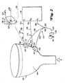
- an on-line apparatus for sensing color blend homogeneity 110 comprises at least a first probe assembly 112, a second probe assembly 114, a light source 116 and a color sensor 118, as shown in FIG. 2.
- First probe assembly 112 and second probe assembly 114 each comprise a light transmissive window 120, a portion of an illumination assembly 122, and a detection assembly 124.
- Light transmissive window 120 is disposed within a sidewall of a mixing vessel 126, typically a blender or the like.
- Light transmissive window 120 must be optically transparent.
- light transmissive window 120 comprises a quartz material or the like.
- Light source 116 is provided for emitting and projecting a light beam to mixing vessel 126.
- Light source 116 may include any light source capable of providing a spectrum through the visible light region, typically avoiding fluorescence.
- color sensor 118 is optically coupled, as described below, to light source 116.
- Color sensor 118 may comprise a spectrometer, a spectrophotometer, a spectrocolorimeter, a spectrophotometric colorimeter, or the like, to perform spectrum color analysis of any incident light supplied thereto.
- illumination assembly 122 comprises a first lens 128, at least a trifurcated optical fiber 130 and at least a pair of second lenses 132.
- First lens 128 is disposed to receive light emitted from light source 116.
- First lens 128 typically comprises a planoconvex lens or the like.
- a light source end 134 of trifurcated optical fiber 130 is aligned with first lens 128 so as to provide an optical coupling at light source 116.
- a light beam emitted from light source 116 is focused by first lens 128 and is injected into light source end 134 of optical fiber 130.
- At a trifurcation point 136 optical fiber 130 splits into a first probe portion 138, a second probe portion 140 and a color sensor portion 142.
- First probe portion 138 and second probe portion 140 of optical fiber 130 are disposed normal to and proximate to light transmissive windows 120 of first probe assembly 112 and second probe assembly 114, respectively.
- Second lens 132 is positioned adjacent light transmissive window 120 of each probe assembly 112 and 114.
- the light beam injected into optical fiber 130 travels through first and second probe portions 138 and 140 is intercepted by respective second lenses 132 and is projected onto respective light transmissive windows 120 so as to illuminate portions of a sample blend 144 within blender 126.
- detection assembly 124 comprises a lens 146 and an optical fiber 148.
- Lenses 146 are positioned adjacent light transmissive window 120 of each respective probe assembly 112 and 114 at an angle ( ⁇ ) with respect to a reference axis 150 so as to detect diffuse reflection from an illuminated sample blend 144 within blender 126.
- Reference axis 150 is aligned essentially perpendicular to light transmissive window 120.
- angle ( ⁇ ) is in the range between about 1° to about 89°. In another example of the instant invention, angle ( ⁇ ) is in the range between about 35° to about 55°.
- a first end 152 of optical fiber 148 is optically coupled to lens 146 such that diffuse reflection directed into lens 146 is injected into first end 152 of optical fiber 148 and is transmitted through optical fiber 148 to a second end 154 of optical fiber 148, which second end 154 is optically coupled to color sensor 118.
- color sensor 118 collects the light from the sample blend 144 from both the first probe assembly 112 and second probe assembly 114. The collected light is transformed by color sensor 118 into tri-color signals. The light is collected and transformed by color sensor into tri-color signals a number of times, typically in the range between about 8 to 30 times.
- sample blend 144 Upon completion of the color sensing of sample blend 144, the average tri-color signal from each probe assembly location is calculated and the standard deviation of the various tri-color signals is calculated with respect to each location. Accordingly, sample blend 144 is uniquely characterized by six values at first probe assembly 112: L av ; a av ; b av ; L st ; a st and b st and six values at second probe assembly 114: L' av ; a' av ; b' av ; L' st ; a' st ; and b' st.
- the standard deviation tri-color signal values at the respective probe locations are compared. If the standard deviation values (L st ; a st ; b st; L' st ; a' st ; and b' st .) are less than a predetermined amount, the blend is characterized as being locally homogeneous. The predetermined amount is satisfied if the standard deviation values are less than about .25 to about 2 L, a, b units.
- the blend is sufficiently mixed when the values indicate the samples are both globally and locally homogeneous. If the values indicate that the samples are not both globally and locally homogeneous, the blending process continues as the constituents are not fully inter-mixed.
- This online blend monitoring process of determining blend homogeneity can be carried out with a controller electrically coupled to color sensor 118.
- the controller comprises circuitry, such as a microprocessor chip or the like.
- FIG. 3 An exemplary control logic sequence for online apparatus 110 is shown in FIG. 3.
- the online blend monitoring by apparatus 110 is started at block 200.
- the average tri-color signal values (L av ; a av ; b av ; L' av ; a' av and b' av ) are determined for each of the respective probe locations.
- the standard deviation tri-color signal values (L st ; a st ; b st ; L' st ; a' st and b' st ) are determined for each of the respective probe iocations.
- an intervening step at block 216 may include turning mixing vessel on before retuming to block 200.
- the process advances to block 216 and the mixing vessel is turned off as the constituents of the blend are adequately inter-mixed.
Description
- This application relates generally to color blend mixing, and in particular relates to sensing blend color homogeneity.
- Modem plastic materials have found a wide range of markets and a variety of applications in diverse manufacturing fields. These plastic materials offer many desirable characteristics such as an excellent finish, desirable electrical, thermal and mechanical properties, low-cost and a variety of colors.
- Plastics are typically formed of one or more base polymers or resins, one or more colorants, and other additives. Such additives may include, for example, fiberglass for structural reinforcement, flame retardents, plasticizers, or mold release agents. The plastics are manufactured by initially mixing these components to form a substantially homogeneous polymer blend. The polymer blend then typically undergoes extrusion, or the like, to form a raw product, for example pellets. The raw products are then utilized to produce final polymer products of various forms.
- Recently, in the field of polymer design, there has been a demand for color polymer blend techniques that make it possible to faithfully reproduce blend colors. The color of the final product may depend on several factors including the concentration and type of colorant and base resin, temperature history during mixing, and the ultimate degree of constituent inter-mixing achieved during processing. Thus, variations in color between polymer products may arise for a variety of reasons.
- For example, color may vary among products due to polymer product formulation or recipe differences. Color variations may exist between lots for a given product formulation or recipe due to machine-to-machine differences. Color differences may exist within lots due to changing raw material characteristics, changing operating conditions, and inaccuracies and other anomalies in processing, including speed rates.
- Polymer color is typically manually adjusted by adjusting the amount of colorant for a given production run. The colorant may take any conventional form which affects the color of the polymer product by itself or in combination with other constituents. For example, solid pigments and liquid pigments or dyes may be used for affecting the color of the final product.
- In a typical production process, the colorant and base resin are blended together and compounded or extruded in a laboratory machine to generate pellets. The pellets are then injection molded to obtain a plaque with substantially uniform color, which is then conventionally measured in a laboratory spectrocolorimeter. The measured plaque color is compared with a reference or standard plaque color, and differences therebetween are corrected by adjusting the colorant. The sequence is repeated until the plaque color falls within an acceptable range to the reference plaque.
- A sample of the finally corrected colorant and resin blend is then compounded on a production scale machine that follows the same procedure as the laboratory machine to produce a color plaque which is again compared with a reference plaque. If required, the color in the production machine is suitably corrected to affect an acceptable match between the measured plaque and the reference plaque.
- This process, therefore, requires many steps to achieve a desired color in the polymer pellets which increases processing time and cost. Accordingly, it is desired to improve the process of constituent inter-mixing in the production of a polymer product from base resins and colorants.
- Document US-A-5 568 266 discloses a colorimeter control device. Document US-A-4 878 756 discloses a method and an apparatus for sensing color.
- According to the present invention, there is provided an apparatus for sensing color blend portion comprising, in one main embodiment, all the characteristics of claim 1. Claim 13 defines another main embodiment. Additional embodiments are defined in dependent claims.
Embodiments of the invention will now be described, by way of example, with reference to the accompanying drawings, in which: - FIG. 1 is a schematic illustration of one embodiment of the instant invention;
- FIG. 2 is a schematic illustration of another embodiment of the instant invention; and
- FIG. 3 is an exemplary control logic flowchart in accordance with one embodiment of the instant invention.
-
- An apparatus for sensing
color blend homogeneity 10 comprises a lighttransmissive plate 12, alight source 14, acolor sensor 16, anillumination assembly 18, and at least onedetection assembly 20, as shown in FIG. 1. - Light
transmissive plate 12 includes atop surface 22 for deposition of respective test samples of amaterial blend 24. Lighttransmissive plate 12 should be optically transparent. In one embodiment, lighttransmissive plate 12 comprises a quartz material or the like. Although the present invention is described herein in connection with lighttransmissive plate 12, the present invention is not limited to practice with lighttransmissive plate 12. The present invention can be implemented and utilized with many other configurations. For example, lighttransmissive plate 12 may be housed within the bottom surface of a storage bin or the like. - In one embodiment, light
transmissive plate 12 further comprises a multi-axis positioner 26. Multi-axis positioner 26 enables manipulation of lighttransmissive plate 12 in three degrees of freedom; z-adjustment to manipulate the height ofplate 12 translated alongreference axis 28, and y-adjustment and x-adjustment to permit sensing over various regions of a respective sample ofblend 24. Multi-axis positioner 26 may further comprise a tilt control tolevel blend 24 by adjusting the pitch and yaw ofplate 12. -
Light source 14 is provided for emitting and projecting a light beam to blend 24.Light source 14 may include any light source capable of providing a spectrum through the visible light region, typically avoiding fluorescence. In one embodiment,light source 14 emits a light beam at a wavelength in the range between about 400 nm to about 770 nm. In one embodiment,light source 14 comprises a tungsten-halogen light source. - In one embodiment of the instant invention,
color sensor 16 is optically coupled, as described below, tolight source 14.Color sensor 16 may comprise a spectrometer, a spectrophotometer, a spectrocolorimeter, a spectrophotometric colorimeter, or the like, to perform spectrum color analysis of any incident light supplied thereto. -
Illumination assembly 18 comprises afirst lens 30, at least a bifurcatedoptical fiber 32 and a second lens 34.First lens 30 is disposed to receive light emitted fromlight source 14.First lens 30 typically comprises a planoconvex lens or the like. Alight source end 36 of bifurcatedoptical fiber 32 is aligned withfirst lens 30 so as to provide an optical coupling atlight source 14. The light beam is emitted fromlight source 14, is focused byfirst lens 30 and is injected intolight source end 36 ofoptical fiber 32. At abifurcation point 38,optical fiber 32 splits into aplate portion 40 and acolor sensor portion 42. -
Plate portion 40 ofoptical fiber 32 is disposed normal to and proximate lighttransmissive plate 12. Second lens 34 is positioned adjacent lighttransmissive plate 12. The light beam injected intooptical fiber 32 passes throughplate portion 40 is intercepted by second lens 34 and is projected onto lighttransmissive plate 12 so as to illuminatesample blend 24. -
Color sensor portion 42 of optical fiber is optically coupled tocolor sensor 16 so as to provide a reference of the signal representing the light beam emitted fromlight source 14. -
Detection assembly 20 comprises afirst detection lens 44 and anoptical fiber 46.First detection lens 44 is disposed adjacent to light transmissive plate at an angle (α) with respect toreference axis 28 so as to detect diffuse reflection from the illuminated sample ofblend 24.Reference axis 28 is aligned essentially perpendicular to lighttransmissive plate 12. - In one example of the instant invention, angle (α) is in the range between about 1° to about 89°. In another example of the instant invention, angle (α) is in the range between about 35° to about 55°. A
first end 48 ofoptical fiber 46 is optically coupled tofirst detection lens 44 such that diffuse reflection directed intofirst detection lens 44 is injected intofirst end 48 ofoptical fiber 46 and is transmitted throughoptical fiber 46 to asecond end 50 ofoptical fiber 46, whichsecond end 50 is optically coupled tocolor sensor 16. - Although the present invention is described as including a
single detection assembly 20, the present invention is not limited to practice with asingle detection assembly 20. The present invention can be implemented and utilized with many other configurations. For example, two ormore detection assemblies 20 may be utilized within the present invention, as shown in FIG 1. -
Color sensor 16 senses the light transmitted throughoptical fiber 46. The collected light fromsample blend 24 is transformed bycolor sensor 16 into signals providing color information, typically values designated by L, a and b or other tri-color signals, for example, RGB, X, Y, Z or the like (hereinafter referred to as "tri-color signal"). For purposes of discussion, tri-color signals will be discussed in terms of L, a, b coordinate system wherein the lightness is typically called L, the red-green coordinate is called a, (positive for red colors and negative for green colors) and the yellow-blue coordinate is called b, (positive for yellow colors and negative for blue colors). This L, a, b coordinate system is a color measuring system that is currently utilized and known in the art. The utilization of the L, a, b coordinate system within this application is for purposes of discussion only and is not a limitation of the instant invention. In fact, the instant invention can be utilized with any known color measurement system . - The tri-color signal generated by
color sensor 16 provides color information about the collected light by measuring the diffusely reflected spectrum fromblend sample 24 and transforming the measured spectrum into standard color units such as L, a and b, or the like. - In accordance with one embodiment of the instant invention,
blend sample 24 and at least a second blend sample (not shown) are removed from at least two locations within a polymer mixing vessel, for example, a blender.First sample 24 is placed onlight transmissive plate 12, as shown in FIG. 1.Light source 14 emits a light beam to blendsample 24 throughillumination assembly 18 and the diffuse reflection ofsample 24 is detected bydetection assembly 20 and is transmitted tocolor sensor 16.Color sensor 16 collects the light fromsample blend 24 and transforms the collected light into a first tri-color signal. - Next, in accordance with one embodiment of the instant invention, the light transmissive plate is moved with respect to
illumination assembly 10, typically by multi-axis positioner 26, such that a different portion of blend sample 24' is illuminated and hence, a second diffuse reflection ofblend sample 24 is detected bydetection assembly 20 and is transmitted tocolor sensor 16. - Accordingly,
color sensor 16 senses the light fromblend sample 24 and transforms the collected light into a second tri-color signal. - This process of manipulating the light transmissive plate and transforming the collected light into a tri-colored signal is performed at a number of locations of
blend sample 24, typically in the range between about 8 to 30 locations. - Upon completion of the color sensing of
blend sample 24, the average tri-color signal from all locations is calculated and the standard deviation of the various tri-color signals is calculated. Accordingly,sample blend 24 is uniquely characterized by six values: Lav; aav; bav; Lst; ast and bst. Lav is the average lightness coordinate, aav is the average red-green coordinate, bav is the average yellow-blue coordinate, Lst is the standard deviation of the lightness coordinates, ast is the standard deviation of the red-green coordinates, and bst is the standard deviation of the yellow-blue coordinates. - Next,
sample blend 24 is replaced by at least a second blend sample and the above described process is completed for the second blend sample such that the second blend sample is also uniquely characterized by six values: L'av; a'av; b'av; L'st; a'st; and b'st. - Next, in one embodiment of the instant invention, the average color difference (ΔE av ) between the respective samples is calculated utilizing the following formula:
- If the value of (ΔE av ) is less than or equal to about 1, the blend is characterized as being globally homogeneous. If the value of (ΔE av ) is greater than about 1, for example about two or about 3, the blend is not globally homogeneous
- Next, the standard deviations of the respective samples are compared. If the standard deviation values (Lst; ast; bst; L'st; a'st; and b'st.) are less than a predetermined amount, the blend is characterized as being locally homogeneous. The predetermined amount is satisfied if the standard deviation values are less than about .25 to about 2 L, a, b units.
- The blend is sufficiently mixed when the values indicate the samples are both globally and locally homogeneous. If the values indicate that the samples are not both globally and locally homogeneous, the blending process continues as the constituents are not fully inter-mixed.
- This entire process of determining blend homogeneity can be carried out with a controller electrically coupled to
color sensor 16. The controller comprises circuitry, such as a microprocessor chip or the like. - In accordance with another embodiment of the instant invention, an on-line apparatus for sensing color blend homogeneity 110 comprises at least a
first probe assembly 112, a second probe assembly 114, alight source 116 and acolor sensor 118, as shown in FIG. 2. -
First probe assembly 112 and second probe assembly 114 each comprise alight transmissive window 120, a portion of anillumination assembly 122, and adetection assembly 124. Lighttransmissive window 120 is disposed within a sidewall of a mixingvessel 126, typically a blender or the like. Lighttransmissive window 120 must be optically transparent. In one embodiment,light transmissive window 120 comprises a quartz material or the like. -
Light source 116 is provided for emitting and projecting a light beam to mixingvessel 126.Light source 116 may include any light source capable of providing a spectrum through the visible light region, typically avoiding fluorescence. - In one embodiment,
color sensor 118 is optically coupled, as described below, tolight source 116.Color sensor 118 may comprise a spectrometer, a spectrophotometer, a spectrocolorimeter, a spectrophotometric colorimeter, or the like, to perform spectrum color analysis of any incident light supplied thereto. - In another example,
illumination assembly 122 comprises afirst lens 128, at least a trifurcatedoptical fiber 130 and at least a pair ofsecond lenses 132.First lens 128 is disposed to receive light emitted fromlight source 116.First lens 128 typically comprises a planoconvex lens or the like. A light source end 134 of trifurcatedoptical fiber 130 is aligned withfirst lens 128 so as to provide an optical coupling atlight source 116. A light beam emitted fromlight source 116 is focused byfirst lens 128 and is injected into light source end 134 ofoptical fiber 130. At atrifurcation point 136optical fiber 130 splits into afirst probe portion 138, asecond probe portion 140 and acolor sensor portion 142. -
First probe portion 138 andsecond probe portion 140 ofoptical fiber 130 are disposed normal to and proximate to lighttransmissive windows 120 offirst probe assembly 112 and second probe assembly 114, respectively.Second lens 132 is positioned adjacentlight transmissive window 120 of eachprobe assembly 112 and 114. The light beam injected intooptical fiber 130 travels through first andsecond probe portions second lenses 132 and is projected onto respective lighttransmissive windows 120 so as to illuminate portions of asample blend 144 withinblender 126. - In one example,
detection assembly 124 comprises alens 146 and anoptical fiber 148.Lenses 146 are positioned adjacentlight transmissive window 120 of eachrespective probe assembly 112 and 114 at an angle (α) with respect to a reference axis 150 so as to detect diffuse reflection from an illuminatedsample blend 144 withinblender 126. Reference axis 150 is aligned essentially perpendicular tolight transmissive window 120. - In one example of the instant invention the angle (α) is in the range between about 1° to about 89°. In another example of the instant invention, angle (α) is in the range between about 35° to about 55°. A
first end 152 ofoptical fiber 148 is optically coupled tolens 146 such that diffuse reflection directed intolens 146 is injected intofirst end 152 ofoptical fiber 148 and is transmitted throughoptical fiber 148 to asecond end 154 ofoptical fiber 148, whichsecond end 154 is optically coupled tocolor sensor 118. - During blending,
color sensor 118 collects the light from thesample blend 144 from both thefirst probe assembly 112 and second probe assembly 114. The collected light is transformed bycolor sensor 118 into tri-color signals. The light is collected and transformed by color sensor into tri-color signals a number of times, typically in the range between about 8 to 30 times. - Upon completion of the color sensing of
sample blend 144, the average tri-color signal from each probe assembly location is calculated and the standard deviation of the various tri-color signals is calculated with respect to each location. Accordingly,sample blend 144 is uniquely characterized by six values at first probe assembly 112: Lav; aav; bav; Lst; ast and bst and six values at second probe assembly 114: L'av; a'av; b'av; L'st; a'st; and b'st. - Next, in one embodiment of the instant invention, the average color difference (ΔE av ) between the respective samples is calculated utilizing the following formula:
- If the value of (ΔE av ) is less than or equal to about 1, the blend is characterized as being globally homogeneous. If the value of (ΔE av ) is greater than about 1, for example about two or about 3, the blend is not globally homogeneous
- Next, the standard deviation tri-color signal values at the respective probe locations are compared. If the standard deviation values (Lst; ast; bst; L'st; a'st; and b'st.) are less than a predetermined amount, the blend is characterized as being locally homogeneous. The predetermined amount is satisfied if the standard deviation values are less than about .25 to about 2 L, a, b units.
- The blend is sufficiently mixed when the values indicate the samples are both globally and locally homogeneous. If the values indicate that the samples are not both globally and locally homogeneous, the blending process continues as the constituents are not fully inter-mixed.
- This online blend monitoring process of determining blend homogeneity can be carried out with a controller electrically coupled to
color sensor 118. The controller comprises circuitry, such as a microprocessor chip or the like. - An exemplary control logic sequence for online apparatus 110 is shown in FIG. 3. The online blend monitoring by apparatus 110 is started at
block 200. - At
blocks 202 and 204, the average tri-color signal values (Lav; aav; bav; L'av; a'av and b'av) are determined for each of the respective probe locations. Atblocks 206 and 208 the standard deviation tri-color signal values (Lst; ast; bst; L'st; a'st and b'st) are determined for each of the respective probe iocations. - Next, at
blocks - Next, at
block 215, a determination is made of whether the blend is globally homogeneous, in the manner described above. If the values indicate the blend is not globally homogeneous, the process returns to block 200 and starts over. If the mixing vessel is in an off position when it is determined that the blend is not globally homogeneous, an intervening step atblock 216 may include turning mixing vessel on before retuming to block 200. - If the values indicate the blend is globally homogeneous, the process advances to block 216 and the mixing vessel is turned off as the constituents of the blend are adequately inter-mixed.
Claims (13)
- An apparatus for sensing color blend homogeneity of at least a first (24) material blend portion, said apparatus comprising:wherein said color sensor (16) is arranged to sense the diffuse reflecting light from said first (24) material blend portion and transform said diffuse reflecting light into tri-color signals so as to determine the local and global homogeneity of said first (24) material blend portion, characterised in that:a light transmission plate (12) for holding said material blend portion;a light source (14) for emitting a lightbeam;a color sensor (16);an illumination assembly (18) having a first end (36) optically coupled to said light source (14) and a second end (40) optically coupled to and disposed normal to said light transmissive plate (12) so as to illuminate said first (24) material blend portion disposed on said light transmission plate with said light beam;at least one detection assembly (20) having a first end (48) disposed adjacent said light transmissive plate (12) so as to detect the diffuse reflection from said illumination of said first (24) material blend portion and a second end (50) optically coupled to said color sensor (16); andsaid illumination assembly (18) comprises a first lens (39) disposed adjacent said light source (14), at least a bifurcated optical fiber (32) having a light source end (36) aligned with said first lens (30) so as to complete an optical coupling at said light source (14) and a second lens (34) disposed adjacent said light transmissive plate (12) so as to intercept said light beam injected into said optical fiber (32) and project said light beam onto said light transmissive plate (12) so as to illuminate said material blend portion, one portion (42) of the bifurcated optical fiber being optically coupled to said color sensor (16) so as to provide a reference of the signal representing the light beam emitted from said light source (14).
- An apparatus for sensing color blend homogeneity in accordance with claim 1, wherein said light source (14) emits a light beam at a wavelength in the range between about 400 nm to about 770 nm.
- An apparatus for sensing color blend homogeneity in accordance with claim 1, wherein said detection assembly (20) comprises a first detection lens (44) disposed adjacent said light transmissive plate (12) at angle (a) with respect to a reference axis (28) so as to detect diffuse reflection from said illuminated material blend portions and an optical fiber (46) coupled to said color sensor (16) so as to transmit said diffuse reflection from said first detection lens 44 to said color sensor (16).
- An apparatus for sensing color blend homogeneity, in accordance with claim 1, wherein said first material blend is disposed on said light transmissive plate and said color sensor collects the diffuse reflection from said first material blend portion and transforms said collected light into a first tri-color signal.
- An apparatus for sensing color blend homogeneity, in accordance with claim 4, wherein said light transmissive plate is movable with respect to said illumination assembly such that a different portion of said first blend sample is illuminated and a second diffuse reflection of said material blend portion is detected by said detection assembly and is transmitted to said color sensor wherein said color sensor collects said light from said first material blend portion and transforms the collected light into a second tri-color signal.
- An apparatus for sensing color blend homogeneity, in accordance with claim 5, wherein said light transmissive plate is movable with respect to said illumination assembly such that different portions of said first material blend portion is illuminated and collected light is transformed into tri-color signals at a plurality of locations of said first material blend portion.
- An apparatus for sensing color blend homogeneity in accordance with claim 6, wherein an average tri-color signal from all locations is calculated and a standard deviation of all the tricolor signals is calculated such that first sample blend portion (24) characterized by six values:(Lav; aav; bav; Lst; ast and bst).
- An apparatus for sensing color blend homogeneity in accordance with claim 7, wherein said first material blend (24) portion (24) is replaced on said light transmissive plate (12) by a second blend sample portion and said process is continued such that said second blend sample portion is also uniquely characterized by six values: (L'av; a'av; b'av; L'st; a'st and b'st).
- An apparatus for sensing color blend homogeneity in accordance with claim 8, wherein said average color difference between said first material blend portion (24) and said second material blend portion is calculated utilizing the formula
- An apparatus for sensing color blend homogeneity in accordance with claim 9, wherein said blend portions are characterized as globally homogeneous when (ΔE av ) is less than about 1.
- An apparatus for sensing color blend homogeneity in accordance with claim 8, wherein said standard deviation tri-color signal values of said first material blend (24) portion and said second material blend portion are analyzed by said controller to detect if said values are less than a predetermined amount so as to characterize said blend portions as locally homogeneous.
- An apparatus for sensing color blend homogeneity in accordance with claim 11, wherein said predetermined amount is less than about .25 to about 2 L, a, b units.
- A material blend mixing vessel (126) including an online apparatus for sensing color blend homogeneity, said apparatus comprising:wherein each of said illumination assemblies (122) has a first end (134) optically coupled to said light source (116) and a second end optically coupled to and disposed normal to said light transmissive windows (120) so as to illuminate portions of said material blend (144) within said mixing vessel (126) with said light beam;a first probe assembly (112) comprising a light transmissive window (120) disposed within a side wall of said mixing vessel (126), an illumination assembly (122) and a detection assembly (124);a second probe assembly (114) comprising a light transmissive window (120) disposed within a second portion of said side wall of said mixing vessel (126), an illumination assembly (122) a detection assembly (124);a light source (116) for emitting a light beam;a color sensor (118);
wherein each of said detection assemblies (124) has a first end (152) disposed adjacent said light transmissive windows (120) so as to detect the diffuse reflection from said illumination of said material blend (144) portions and a second end (154) optically coupled to said color sensor (118); and
wherein said color sensor (118) is arranged to collect the diffuse reflecting light from said first and second probe assemblies (112, 114) and transform said diffuse reflecting light into tri-color signals so as to determine the local and global homogeneity of said material blend (144), characterised in that:each said illumination assembly (122) comprises a first lens (128) disposed adjacent said light source (116), at least a bifurcated optical fiber (130) having a light source end (134) aligned with said first lens (128) so as to complete an optical coupling at said light source (116) and a second lens (132) disposed adjacent said light transmissive window (120) so as to intercept said light beam injected into said optical fiber (130) and project said light beam onto said light transmissive window (120) so as to illuminate said material blend portions, one portion (142) of the bifurcated optical fiber being optically coupled to said color sensor (116) so as to provide a reference of the signal representing the light beam emitted from said light source (116).
Applications Claiming Priority (2)
| Application Number | Priority Date | Filing Date | Title |
|---|---|---|---|
| US926084 | 1997-09-02 | ||
| US08/926,084 US5859708A (en) | 1997-09-02 | 1997-09-02 | Sensing blend color homogeneity |
Publications (3)
| Publication Number | Publication Date |
|---|---|
| EP0901004A2 EP0901004A2 (en) | 1999-03-10 |
| EP0901004A3 EP0901004A3 (en) | 2000-03-29 |
| EP0901004B1 true EP0901004B1 (en) | 2005-06-29 |
Family
ID=25452735
Family Applications (1)
| Application Number | Title | Priority Date | Filing Date |
|---|---|---|---|
| EP98306959A Expired - Lifetime EP0901004B1 (en) | 1997-09-02 | 1998-08-28 | Sensing blend color homogeneity |
Country Status (6)
| Country | Link |
|---|---|
| US (1) | US5859708A (en) |
| EP (1) | EP0901004B1 (en) |
| JP (1) | JPH11132852A (en) |
| DE (1) | DE69830691T2 (en) |
| ES (1) | ES2244035T3 (en) |
| SG (1) | SG67541A1 (en) |
Families Citing this family (16)
| Publication number | Priority date | Publication date | Assignee | Title |
|---|---|---|---|---|
| US6075608A (en) * | 1998-05-11 | 2000-06-13 | General Electric Company | Blend segregation detection |
| SE9802690D0 (en) * | 1998-08-07 | 1998-08-07 | Astra Ab | Mixing apparatus |
| US5943127A (en) * | 1998-11-09 | 1999-08-24 | General Electric Company | Coined line analyzer |
| US6868371B1 (en) * | 1999-05-03 | 2005-03-15 | General Electric Company | System and method to quantify appearance defects in molded plastic parts |
| US6306319B1 (en) * | 1999-07-19 | 2001-10-23 | Chroma Corporation | Method of determining wear |
| US6539278B1 (en) * | 1999-09-20 | 2003-03-25 | General Electric Company | Method and apparatus for resin formulations with improved streaking performance |
| WO2001029539A1 (en) * | 1999-10-20 | 2001-04-26 | Massachusetts Institute Of Technology | Systems and methods for analyzing mixtures using fluorescence |
| US6469789B1 (en) | 2000-08-22 | 2002-10-22 | General Electric Company | On-line color measurement system for cooled product |
| US20030168758A1 (en) * | 2002-03-07 | 2003-09-11 | Bickel Jeffrey L. | Plastic color blender and method |
| US7057722B2 (en) * | 2002-04-04 | 2006-06-06 | Euro-Celtique S.A. | Method and apparatus for determining the homogeneity of a granulation during tableting |
| WO2003094679A2 (en) * | 2002-05-09 | 2003-11-20 | Euro-Celtique, S.A. | Spectroscopic analyzer for blender |
| US6895445B2 (en) * | 2002-05-28 | 2005-05-17 | Mercurymd, Inc. | Docking stations for transferring data between handheld electronic devices and other devices via infrared communications |
| JP4939910B2 (en) * | 2006-11-29 | 2012-05-30 | 株式会社東芝 | Micro chemical analysis system and micro chemical analysis device |
| CA2735892A1 (en) * | 2008-09-29 | 2010-04-01 | Johanson Holdings, Llc | Mixture segregation testing devices and methods |
| US20120190780A1 (en) | 2011-01-25 | 2012-07-26 | Danielson Todd D | Additive compositions and thermoplastic polymer compositions comprising the same |
| KR20240036127A (en) | 2018-12-21 | 2024-03-19 | 밀리켄 앤드 캄파니 | Additive compositions and thermoplastic polymer compositions comprising the same |
Family Cites Families (9)
| Publication number | Priority date | Publication date | Assignee | Title |
|---|---|---|---|---|
| DE2947791C2 (en) * | 1979-11-28 | 1985-04-18 | Licentia Patent-Verwaltungs-Gmbh, 6000 Frankfurt | Device for color monitoring of sheet-like or web-shaped materials in motion, in particular the printing materials of printing machines |
| US4841140A (en) * | 1987-11-09 | 1989-06-20 | Honeywell Inc. | Real-time color comparator |
| JPH0778455B2 (en) * | 1990-12-28 | 1995-08-23 | 哲也 村岡 | Color unevenness automatic identification device |
| EP0637731B1 (en) * | 1993-08-06 | 1998-11-04 | Toyota Jidosha Kabushiki Kaisha | Method of color reproduction |
| ES2140510T3 (en) * | 1993-10-04 | 2000-03-01 | Gen Electric | SYSTEM TO CONTROL THE COLOR OF ONE OR MULTIPLE POLYMERS IN COMPOSITION USING COLOR MEASUREMENTS DURING THEIR TREATMENT. |
| GB2293448B (en) * | 1994-09-20 | 1996-12-11 | Honda Motor Co Ltd | Method of determining color tone of glitter-containing coating |
| US5568266A (en) * | 1994-09-28 | 1996-10-22 | Mts Colorimetrie | Colorimeter and colorimetrical control device |
| US5642192A (en) * | 1995-06-12 | 1997-06-24 | Measurex Corporation | Dual spectrometer color sensor |
| US5650942A (en) * | 1996-02-02 | 1997-07-22 | Light Source Computer Images, Inc. | Appearance-based technique for rendering colors on an output device |
-
1997
- 1997-09-02 US US08/926,084 patent/US5859708A/en not_active Expired - Fee Related
-
1998
- 1998-08-20 SG SG1998003162A patent/SG67541A1/en unknown
- 1998-08-28 DE DE69830691T patent/DE69830691T2/en not_active Expired - Fee Related
- 1998-08-28 EP EP98306959A patent/EP0901004B1/en not_active Expired - Lifetime
- 1998-08-28 ES ES98306959T patent/ES2244035T3/en not_active Expired - Lifetime
- 1998-09-02 JP JP10247888A patent/JPH11132852A/en active Pending
Also Published As
| Publication number | Publication date |
|---|---|
| DE69830691T2 (en) | 2006-05-04 |
| US5859708A (en) | 1999-01-12 |
| EP0901004A2 (en) | 1999-03-10 |
| EP0901004A3 (en) | 2000-03-29 |
| SG67541A1 (en) | 1999-09-21 |
| JPH11132852A (en) | 1999-05-21 |
| DE69830691D1 (en) | 2005-08-04 |
| ES2244035T3 (en) | 2005-12-01 |
Similar Documents
| Publication | Publication Date | Title |
|---|---|---|
| EP0901004B1 (en) | Sensing blend color homogeneity | |
| US5963332A (en) | Internal color probe | |
| CN1288418C (en) | Measurement of hot container wall thickness | |
| US8340937B2 (en) | Characterization of a model-based spectral reflectance sensing device | |
| KR20030032433A (en) | The inspection method of thin film and the same apparatus | |
| CN102759403A (en) | Method for quantifying color of sample | |
| JPH09288007A (en) | Spectral colorimeter | |
| CN101655455B (en) | Paper color online detecting system for paper production line | |
| US5963334A (en) | Apparatus and method for measuring color of a measurement object | |
| US6075608A (en) | Blend segregation detection | |
| US5739914A (en) | Colorimetric instrument | |
| US20040196462A1 (en) | Method for coloring plastic by using plastic recycling material | |
| GB2496897A (en) | Measurement of colour strength of a diffusely reflective liquid e.g. paint | |
| CN115371570A (en) | Method for obtaining film thickness based on chromaticity coordinate measurement | |
| US20060274316A1 (en) | Measuring system for the optical characterization of materials and method for the implementation thereof by said system | |
| US6661915B1 (en) | Illumination variable colorimetric method and colorimeter | |
| CN105372239B (en) | Urine desiccation analytical equipment and analysis method based on optical fiber | |
| JPH0676920B2 (en) | Color unevenness evaluation method for colored molded products | |
| CN107589077A (en) | A kind of blue phase test evaluation method of resin black section | |
| US20050012939A1 (en) | Method and apparatus for quantifying the degree of fusion of a layer | |
| JP2009271060A (en) | Appearance evaluating method for colored article | |
| Stockline | Process condition monitoring | |
| Reshadat et al. | In-line Color Monitoring of Pigmented Polyolefins During Extrusion. I. Assessment | |
| Marszalec et al. | Non-destructive testing of the quality of naturally white food products | |
| JPS617446A (en) | Surface measuring device of linear body |
Legal Events
| Date | Code | Title | Description |
|---|---|---|---|
| PUAI | Public reference made under article 153(3) epc to a published international application that has entered the european phase |
Free format text: ORIGINAL CODE: 0009012 |
|
| AK | Designated contracting states |
Kind code of ref document: A2 Designated state(s): DE ES FR GB IT NL |
|
| AX | Request for extension of the european patent |
Free format text: AL;LT;LV;MK;RO;SI |
|
| PUAL | Search report despatched |
Free format text: ORIGINAL CODE: 0009013 |
|
| AK | Designated contracting states |
Kind code of ref document: A3 Designated state(s): AT BE CH CY DE DK ES FI FR GB GR IE IT LI LU MC NL PT SE |
|
| AX | Request for extension of the european patent |
Free format text: AL;LT;LV;MK;RO;SI |
|
| 17P | Request for examination filed |
Effective date: 20000929 |
|
| AKX | Designation fees paid |
Free format text: DE ES FR GB IT NL |
|
| 17Q | First examination report despatched |
Effective date: 20031017 |
|
| GRAP | Despatch of communication of intention to grant a patent |
Free format text: ORIGINAL CODE: EPIDOSNIGR1 |
|
| GRAS | Grant fee paid |
Free format text: ORIGINAL CODE: EPIDOSNIGR3 |
|
| GRAA | (expected) grant |
Free format text: ORIGINAL CODE: 0009210 |
|
| AK | Designated contracting states |
Kind code of ref document: B1 Designated state(s): DE ES FR GB IT NL |
|
| REG | Reference to a national code |
Ref country code: GB Ref legal event code: FG4D |
|
| REF | Corresponds to: |
Ref document number: 69830691 Country of ref document: DE Date of ref document: 20050804 Kind code of ref document: P |
|
| REG | Reference to a national code |
Ref country code: ES Ref legal event code: FG2A Ref document number: 2244035 Country of ref document: ES Kind code of ref document: T3 |
|
| ET | Fr: translation filed | ||
| PLBE | No opposition filed within time limit |
Free format text: ORIGINAL CODE: 0009261 |
|
| STAA | Information on the status of an ep patent application or granted ep patent |
Free format text: STATUS: NO OPPOSITION FILED WITHIN TIME LIMIT |
|
| 26N | No opposition filed |
Effective date: 20060330 |
|
| PGFP | Annual fee paid to national office [announced via postgrant information from national office to epo] |
Ref country code: ES Payment date: 20070827 Year of fee payment: 10 |
|
| PGFP | Annual fee paid to national office [announced via postgrant information from national office to epo] |
Ref country code: GB Payment date: 20070830 Year of fee payment: 10 |
|
| PGFP | Annual fee paid to national office [announced via postgrant information from national office to epo] |
Ref country code: NL Payment date: 20070824 Year of fee payment: 10 Ref country code: IT Payment date: 20070829 Year of fee payment: 10 Ref country code: DE Payment date: 20071001 Year of fee payment: 10 |
|
| PGFP | Annual fee paid to national office [announced via postgrant information from national office to epo] |
Ref country code: FR Payment date: 20070817 Year of fee payment: 10 |
|
| GBPC | Gb: european patent ceased through non-payment of renewal fee |
Effective date: 20080828 |
|
| NLV4 | Nl: lapsed or anulled due to non-payment of the annual fee |
Effective date: 20090301 |
|
| PG25 | Lapsed in a contracting state [announced via postgrant information from national office to epo] |
Ref country code: NL Free format text: LAPSE BECAUSE OF NON-PAYMENT OF DUE FEES Effective date: 20090301 |
|
| REG | Reference to a national code |
Ref country code: FR Ref legal event code: ST Effective date: 20090430 |
|
| PG25 | Lapsed in a contracting state [announced via postgrant information from national office to epo] |
Ref country code: IT Free format text: LAPSE BECAUSE OF NON-PAYMENT OF DUE FEES Effective date: 20080828 Ref country code: FR Free format text: LAPSE BECAUSE OF NON-PAYMENT OF DUE FEES Effective date: 20080901 Ref country code: DE Free format text: LAPSE BECAUSE OF NON-PAYMENT OF DUE FEES Effective date: 20090303 |
|
| REG | Reference to a national code |
Ref country code: ES Ref legal event code: FD2A Effective date: 20080829 |
|
| PG25 | Lapsed in a contracting state [announced via postgrant information from national office to epo] |
Ref country code: GB Free format text: LAPSE BECAUSE OF NON-PAYMENT OF DUE FEES Effective date: 20080828 |
|
| PG25 | Lapsed in a contracting state [announced via postgrant information from national office to epo] |
Ref country code: ES Free format text: LAPSE BECAUSE OF NON-PAYMENT OF DUE FEES Effective date: 20080829 |