EP0900939A1 - Scroll compressor - Google Patents
Scroll compressor Download PDFInfo
- Publication number
- EP0900939A1 EP0900939A1 EP98115851A EP98115851A EP0900939A1 EP 0900939 A1 EP0900939 A1 EP 0900939A1 EP 98115851 A EP98115851 A EP 98115851A EP 98115851 A EP98115851 A EP 98115851A EP 0900939 A1 EP0900939 A1 EP 0900939A1
- Authority
- EP
- European Patent Office
- Prior art keywords
- scroll
- swirling
- partition
- closed housing
- discharge cavity
- Prior art date
- Legal status (The legal status is an assumption and is not a legal conclusion. Google has not performed a legal analysis and makes no representation as to the accuracy of the status listed.)
- Granted
Links
- 230000006835 compression Effects 0.000 claims abstract description 14
- 238000007906 compression Methods 0.000 claims abstract description 14
- 238000005192 partition Methods 0.000 claims abstract description 12
- 230000001105 regulatory effect Effects 0.000 claims abstract description 5
- 238000004873 anchoring Methods 0.000 claims abstract description 3
- 239000003507 refrigerant Substances 0.000 description 16
- 230000002093 peripheral effect Effects 0.000 description 5
- 238000005057 refrigeration Methods 0.000 description 2
- 238000005299 abrasion Methods 0.000 description 1
- 230000004913 activation Effects 0.000 description 1
- 238000004378 air conditioning Methods 0.000 description 1
- 230000007423 decrease Effects 0.000 description 1
- 230000000149 penetrating effect Effects 0.000 description 1
Images


Classifications
-
- F—MECHANICAL ENGINEERING; LIGHTING; HEATING; WEAPONS; BLASTING
- F04—POSITIVE - DISPLACEMENT MACHINES FOR LIQUIDS; PUMPS FOR LIQUIDS OR ELASTIC FLUIDS
- F04C—ROTARY-PISTON, OR OSCILLATING-PISTON, POSITIVE-DISPLACEMENT MACHINES FOR LIQUIDS; ROTARY-PISTON, OR OSCILLATING-PISTON, POSITIVE-DISPLACEMENT PUMPS
- F04C29/00—Component parts, details or accessories of pumps or pumping installations, not provided for in groups F04C18/00 - F04C28/00
- F04C29/12—Arrangements for admission or discharge of the working fluid, e.g. constructional features of the inlet or outlet
- F04C29/124—Arrangements for admission or discharge of the working fluid, e.g. constructional features of the inlet or outlet with inlet and outlet valves specially adapted for rotary or oscillating piston pumps
- F04C29/126—Arrangements for admission or discharge of the working fluid, e.g. constructional features of the inlet or outlet with inlet and outlet valves specially adapted for rotary or oscillating piston pumps of the non-return type
- F04C29/128—Arrangements for admission or discharge of the working fluid, e.g. constructional features of the inlet or outlet with inlet and outlet valves specially adapted for rotary or oscillating piston pumps of the non-return type of the elastic type, e.g. reed valves
-
- F—MECHANICAL ENGINEERING; LIGHTING; HEATING; WEAPONS; BLASTING
- F04—POSITIVE - DISPLACEMENT MACHINES FOR LIQUIDS; PUMPS FOR LIQUIDS OR ELASTIC FLUIDS
- F04C—ROTARY-PISTON, OR OSCILLATING-PISTON, POSITIVE-DISPLACEMENT MACHINES FOR LIQUIDS; ROTARY-PISTON, OR OSCILLATING-PISTON, POSITIVE-DISPLACEMENT PUMPS
- F04C28/00—Control of, monitoring of, or safety arrangements for, pumps or pumping installations specially adapted for elastic fluids
- F04C28/28—Safety arrangements; Monitoring
Definitions
- the present invention relates to a scroll compressor used to compress refrigerant gas of a refrigerator for an air conditioning device.
- the present application is based on Japanese Patent Application No. Hei 9-257982, the contents of which are herein incorporated by reference.
- FIG. 3 A vertical cross section of a conventional scroll compressor is shown in Fig. 3.
- a cup-shaped housing 2 and a front housing 6 form a closed housing 1, and within this closed housing 1, a fixed scroll 10 and a swirling scroll 14 are disposed.
- the swirling scroll 14 produces a revolution swirling motion while meshing with the fixed scroll 10.
- the fixed scroll 10 is provided with an end plate 11 and a spiral wrap 12 projecting from the inner surface thereof, and the end plate 11 is fastened to the cup-shaped body 2 by a bolt (not shown).
- a space within the closed housing 1 is separated by bringing the outer peripheral surface of the end plate 11 into contact with the inner peripheral surface of the cup-shaped body 2, so that a discharge cavity 31 is formed by the outer side of the end plate 11 and a suction chamber 28 is formed by the inner side of the end plate 11.
- a pressure relief valve 60 is mounted on the cup-shaped housing 2, and when the pressure of the refrigerant gas in the discharge cavity 31 rises abnormally, this pressure relief valve 60 opens, expels this gas out of the closed housing 1. Therefore, when the pressure of the refrigerant gas in the discharge cavity 31 rises abnormally and this relief valve 60 opens, the performance of the refrigerating apparatus subsequently deteriorates if the refrigerant gas is not supplied to the refrigerant gas circuit.
- the present invention provides a scroll compressor which can maintain performance of a refrigeration apparatus such as an air conditioner, without resupplying refrigerant gas to the refrigeration circuit even after refrigerant gas is discharged from the discharge cavity 31 when the pressure of the refrigerant gas rises abnormally in the discharge cavity31.
- the scroll compressor of the present invention comprises a closed housing, a fixed scroll disposed in the closed housing; a swirling scroll disposed in the closed housing, meshing with the fixed scroll, and moving in a swirling motion; a compression chamber formed by the meshing of the fixed scroll and the swirling scroll; a suction chamber connected to the compression chamber; an discharge cavity connected to the compression chamber; a partition separating the discharge cavity and the suction chamber; an exhaust valve provided between said compression chamber and discharge cavity; a retainer for regulating the head of the exhaust valve; and a pressure relief valve installed extending through the partition and anchoring the exhaust valve and the retainer to the partition.
- the pressure relief valve installed the partition that separates the discharge cavity and the suction chamber, when the pressure of the refrigerant gas in the discharge chamber rises abnormally, this pressure relief valve opens and can discharge the refrigerant gas inside the discharge chamber into the suction chamber. Because the suction chamber resides within the closed housing, it is not necessary to supply new refrigerant gas when this discharge occurs.
- Fig. 1 is a vertical cross-sectional view of a scroll compressor according to an embodiment of the present invention.
- reference numeral 1 denotes a closed housing comprising a cup-shaped body 2 and a front housing 6 attached to the cup-shaped body 2 by a bolt (not shown).
- the rotating shaft 7 extending through the front housing 6 is supported so that it rotates freely in the front housing 6 via the bearings 8, 9.
- a fixed scroll 10 and a swirling scroll 14 are disposed in the closed housing 1.
- the fixed scroll 10 is provided with an end plate 11 and a spiral wrap 12 projecting from the inner surface thereof, and the end plate 11 is fastened to the cup-shaped body 2 by a bolt (not shown).
- a space within the closed housing 1 is delimited by bringing the '0' ring 34 of the outer peripheral surface of the end plate 11 into contact with an inner peripheral surface of the cup-shaped body 2, so that a discharge cavity 31 is formed in the outer side of the end plate 11 and a suction chamber 28 is formed in the inner side of the end plate 11.
- This end plate 11 is a partition of the present invention.
- a discharge port 29 penetrates the center of the end plate 11, and the discharge port 29 is structured in such a manner as to be opened and closed by a exaust valve 30.
- the head of the exaust valve 30 is regulated by the retainer 32, and one end of the exhaust valve 30 and the retainer 32 is attached to the end plate 11 by a pressure relief valve 50.
- a detailed description of the pressure relief valve 50 will be given below.
- the swirling scroll 14 is provided with an end plate 15 and a spiral wrap 16 projecting from the inner surface thereof, the spiral wrap 16 having substantially the same shape as that of the spiral wrap 12 of the fixed scroll 10.
- the swirling scroll 14 and the fixed scroll 10 mesh with each other eccentrically at a and the fixed scroll 10 mesh with each other eccentrically at a fixed distance, and are shifted only 180°.
- a tip seal 17 mounted in the front end surface of the spiral wrap 12 is in close contact with the inner surface of the end plate 15, and a tip seal 18 mounted in a front end surface of the spiral wrap 16 is in close contact with the inner surface of the end plate 11, so that the side surfaces of the spiral wrap 12 and 16 are in line contact at a plurality of locations, whereby a plurality of compressing chambers 19a and 19b are formed in point symmetry with respect to the center of the spiral.
- a drive bush 21 rotatably engages the inner part of a cylindrical boss 20 projecting from the center part of the outer surface of the end plate 15 via a swirling bearing 23, and an eccentric drive pin 25 projecting from the inner end of the rotating shaft 7 engaged so as to freely slide in a slide groove 24 penetrating the drive bush 21.
- a balance weight 27 for balancing a dynamic imbalance due to the revolution swirling motion of the swirling scroll 14 is mounted to the drive bush 21, and a balance weight 37 is mounted to the rotating shaft 7.
- a rotation stopping mechanism comprising a thrust bearing 36 and an Oldham ring 26 is interposed between the peripheral edge of the outer surface of the end plate 15 of the swirling scroll 14 and the inner end surface of the front housing 6.
- the swirling scroll 14 When the rotating shaft 7 is caused to rotate, the swirling scroll 14 is driven via a swirling activation mechanism comprising an eccentric drive pin 25, a slide groove 24, a drive bush 21, a swirling bearing 23, and a boss 20, and the swirling scroll 14 travels in a revolution swirling motion on a circular path whose radius is the revolution swirling radius. Otherwise, its free rotation is prevented by the Oldham ring 26.
- a swirling activation mechanism comprising an eccentric drive pin 25, a slide groove 24, a drive bush 21, a swirling bearing 23, and a boss 20, and the swirling scroll 14 travels in a revolution swirling motion on a circular path whose radius is the revolution swirling radius. Otherwise, its free rotation is prevented by the Oldham ring 26.
- the refrigerant gas flowing into the suction chamber 28 through suction port 38 and suction path 39 is introduced into the respective compression chambers 19a, 19b from the outer end opening of the spiral wraps 12, 16, is fed to the center chamber 22 under pressure. From there it passes though exhaust port 29, and pushing open the exhaust valve 30, is discharged into discharge cavity 31, and next flows out through a discharge pipe (not shown)to circulate through the refrigerant circuit comprising the condenser, expansion valve, and evaporator.
- the pressure relief valve 50 anchors the exhaust valve 30 and the retainer 32 by extending through the end plate 11 of the fixed scroll 10.
- the pressure relief valve 50 has the external form of a bolt, being formed with screw threading 57 on the outer perimeter of the end of its shaft 56.
- the gas path 59 which extends therethrough is formed, and its head 55 forming gas entrance 51, and the end of the shaft 56 forming the gas exit54.
- the pressure relief valve 50 opens, the gas inside the discharge cavity 31 is discharged into the section chamber 28, that is, inside the closed housing 1, and because it is not discharged outside the closed housing 1 as happens conventionally, it is not necessary to resupply refrigerant gas to the refrigerant circuit.
Abstract
Description
- The present invention relates to a scroll compressor used to compress refrigerant gas of a refrigerator for an air conditioning device. The present application is based on Japanese Patent Application No. Hei 9-257982, the contents of which are herein incorporated by reference.
- A vertical cross section of a conventional scroll compressor is shown in Fig. 3.
- In Fig. 3, a cup-
shaped housing 2 and afront housing 6 form a closed housing 1, and within this closed housing 1, afixed scroll 10 and aswirling scroll 14 are disposed. Theswirling scroll 14 produces a revolution swirling motion while meshing with thefixed scroll 10. - The
fixed scroll 10 is provided with an end plate 11 and aspiral wrap 12 projecting from the inner surface thereof, and the end plate 11 is fastened to the cup-shaped body 2 by a bolt (not shown). - A space within the closed housing 1 is separated by bringing the outer peripheral surface of the end plate 11 into contact with the inner peripheral surface of the cup-
shaped body 2, so that a discharge cavity 31 is formed by the outer side of the end plate 11 and asuction chamber 28 is formed by the inner side of the end plate 11. - In the above-described conventional scroll compressor, a
pressure relief valve 60 is mounted on the cup-shaped housing 2, and when the pressure of the refrigerant gas in the discharge cavity 31 rises abnormally, thispressure relief valve 60 opens, expels this gas out of the closed housing 1. Therefore, when the pressure of the refrigerant gas in the discharge cavity 31 rises abnormally and thisrelief valve 60 opens, the performance of the refrigerating apparatus subsequently deteriorates if the refrigerant gas is not supplied to the refrigerant gas circuit. - In consideration of the above, the present invention provides a scroll compressor which can maintain performance of a refrigeration apparatus such as an air conditioner, without resupplying refrigerant gas to the refrigeration circuit even after refrigerant gas is discharged from the discharge cavity 31 when the pressure of the refrigerant gas rises abnormally in the discharge cavity31.
- In order to solve the above problem, the scroll compressor of the present invention comprises a closed housing, a fixed scroll disposed in the closed housing; a swirling scroll disposed in the closed housing, meshing with the fixed scroll, and moving in a swirling motion; a compression chamber formed by the meshing of the fixed scroll and the swirling scroll; a suction chamber connected to the compression chamber; an discharge cavity connected to the compression chamber; a partition separating the discharge cavity and the suction chamber; an exhaust valve provided between said compression chamber and discharge cavity; a retainer for regulating the head of the exhaust valve; and a pressure relief valve installed extending through the partition and anchoring the exhaust valve and the retainer to the partition.
- According to the scroll compressor of the present invention, the pressure relief valve installed the partition that separates the discharge cavity and the suction chamber, when the pressure of the refrigerant gas in the discharge chamber rises abnormally, this pressure relief valve opens and can discharge the refrigerant gas inside the discharge chamber into the suction chamber. Because the suction chamber resides within the closed housing, it is not necessary to supply new refrigerant gas when this discharge occurs.
- Because the exhaust valve and the retainer for regulating the head of the exhaust valve are anchored to the end plate of the fixed scroll by the pressure relief valve, the bolt conventionally used to fasten the exhaust valve and the retainer is unnecessary, reducing the cost.
-
- Fig. 1 is a vertical-cross section view which shows a scroll compressor according to an embodiment of the present invention.
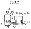
- Fig. 2 is a vertical-cross section view which shows a pressure relief valve comprising the embodiment.
- Fig. 3 is a vertical-cross section view which shows the conventional scroll compressor.
-
- The present invention will be described below on the basis of an embodiment.
- Fig. 1 is a vertical cross-sectional view of a scroll compressor according to an embodiment of the present invention.
- In Fig. 1, reference numeral 1 denotes a closed housing comprising a cup-
shaped body 2 and afront housing 6 attached to the cup-shaped body 2 by a bolt (not shown). The rotating shaft 7 extending through thefront housing 6 is supported so that it rotates freely in thefront housing 6 via thebearings 8, 9. - A
fixed scroll 10 and aswirling scroll 14 are disposed in the closed housing 1. Thefixed scroll 10 is provided with an end plate 11 and aspiral wrap 12 projecting from the inner surface thereof, and the end plate 11 is fastened to the cup-shaped body 2 by a bolt (not shown). - A space within the closed housing 1 is delimited by bringing the '0'
ring 34 of the outer peripheral surface of the end plate 11 into contact with an inner peripheral surface of the cup-shaped body 2, so that a discharge cavity 31 is formed in the outer side of the end plate 11 and asuction chamber 28 is formed in the inner side of the end plate 11. This end plate 11 is a partition of the present invention. - Further, a
discharge port 29 penetrates the center of the end plate 11, and thedischarge port 29 is structured in such a manner as to be opened and closed by aexaust valve 30. The head of theexaust valve 30 is regulated by theretainer 32, and one end of theexhaust valve 30 and theretainer 32 is attached to the end plate 11 by apressure relief valve 50. A detailed description of thepressure relief valve 50 will be given below. - The
swirling scroll 14 is provided with anend plate 15 and aspiral wrap 16 projecting from the inner surface thereof, thespiral wrap 16 having substantially the same shape as that of thespiral wrap 12 of thefixed scroll 10. The swirling scroll 14 and thefixed scroll 10 mesh with each other eccentrically at a and thefixed scroll 10 mesh with each other eccentrically at a fixed distance, and are shifted only 180°. - A
tip seal 17 mounted in the front end surface of thespiral wrap 12 is in close contact with the inner surface of theend plate 15, and atip seal 18 mounted in a front end surface of thespiral wrap 16 is in close contact with the inner surface of the end plate 11, so that the side surfaces of thespiral wrap compressing chambers 19a and 19b are formed in point symmetry with respect to the center of the spiral. - A drive bush 21 rotatably engages the inner part of a cylindrical boss 20 projecting from the center part of the outer surface of the
end plate 15 via aswirling bearing 23, and aneccentric drive pin 25 projecting from the inner end of the rotating shaft 7 engaged so as to freely slide in a slide groove 24 penetrating the drive bush 21. - A
balance weight 27 for balancing a dynamic imbalance due to the revolution swirling motion of theswirling scroll 14 is mounted to the drive bush 21, and abalance weight 37 is mounted to the rotating shaft 7. - In addition, a rotation stopping mechanism comprising a thrust bearing 36 and an Oldham
ring 26 is interposed between the peripheral edge of the outer surface of theend plate 15 of theswirling scroll 14 and the inner end surface of thefront housing 6. - When the rotating shaft 7 is caused to rotate, the
swirling scroll 14 is driven via a swirling activation mechanism comprising aneccentric drive pin 25, a slide groove 24, a drive bush 21, a swirlingbearing 23, and a boss 20, and the swirling scroll 14 travels in a revolution swirling motion on a circular path whose radius is the revolution swirling radius. Otherwise, its free rotation is prevented by the Oldhamring 26. - The side surfaces of the
spiral wraps compression chambers 19a and 19b move in the direction of the center of the spiral, while reducing the volume thereof. - At the same time, the refrigerant gas flowing into the
suction chamber 28 throughsuction port 38 andsuction path 39 is introduced into therespective compression chambers 19a, 19b from the outer end opening of thespiral wraps center chamber 22 under pressure. From there it passes thoughexhaust port 29, and pushing open theexhaust valve 30, is discharged into discharge cavity 31, and next flows out through a discharge pipe (not shown)to circulate through the refrigerant circuit comprising the condenser, expansion valve, and evaporator. - The
pressure relief valve 50 anchors theexhaust valve 30 and theretainer 32 by extending through the end plate 11 of thefixed scroll 10. - As shown in Fig. 2, the
pressure relief valve 50 has the external form of a bolt, being formed with screw threading 57 on the outer perimeter of the end of itsshaft 56. In addition, along its shaft, the gas path 59 which extends therethrough is formed, and its head 55 forminggas entrance 51, and the end of theshaft 56 forming the gas exit54. - Thus, when the pressure of the refrigerant gas inside the discharge cavity 31 rises abnormally, the gas is expelled into the
suction chamber 28 from thegas exit 54 by pushing open the valve 52 (in the rightward direction in the figure) to overcome the tension of thespring 53. 58 is the spring shoe and 61 is the 'O' ring. - Thus, because the pressure inside the discharge cavity 31 decreases due to the opening of the
pressure relief valve 50, abrasion of thescroll wrap 12 of thefixed scroll 10 and the scroll wrap 19 of theswirling scroll 14 can be prevented. - In addition, when the
pressure relief valve 50 opens, the gas inside the discharge cavity 31 is discharged into thesection chamber 28, that is, inside the closed housing 1, and because it is not discharged outside the closed housing 1 as happens conventionally, it is not necessary to resupply refrigerant gas to the refrigerant circuit. - Finally, because the
exhaust valve 30 and theretainer 32 are anchored to the end plate 11 of thefixed scroll 10 by the pressure relief valve50, the bolt conventionally used to fasten theexhaust valve 30 and theretainer 32 is unnecessary, reducing the cost.
Claims (2)
- A scroll compressor comprising:a closed housing(1);a fixed scroll(10) disposed in said closed housing(1);a swirling scroll(14) disposed in said closed housing(1), and meshing with said fixed scroll (10), and moving in a swirling motion;a compression chamber(19a,19b) formed by the meshing of said fixed scroll(10) and said swirling scroll(14);a suction chamber(28) connected to said compression chamber(19a,19b);an discharge cavity(31) connected to said compression chamber(19a,19b);a partition(11) separating said discharge cavity(31) from said suction chamber(28);an exhaust valve(30) provided between said compression chamber(19a,19b) and discharge cavity(31);a retainer(32) for regulating the head of said exhaust valve(30);characterized by a pressure relief valve(50) attached extending through said partition(11), while anchoring said exhaust valve(30) and retainer(32) to said partition(11).
- A scroll compressor according to claim 1, wherein a screw(57) is mounted on the periphery of said relief valve(50) and is attached to said partition(11).
Applications Claiming Priority (3)
| Application Number | Priority Date | Filing Date | Title |
|---|---|---|---|
| JP25798297 | 1997-09-08 | ||
| JP25798297A JP3764566B2 (en) | 1997-09-08 | 1997-09-08 | Scroll compressor |
| JP257982/97 | 1997-09-08 |
Publications (2)
| Publication Number | Publication Date |
|---|---|
| EP0900939A1 true EP0900939A1 (en) | 1999-03-10 |
| EP0900939B1 EP0900939B1 (en) | 2003-10-29 |
Family
ID=17313910
Family Applications (1)
| Application Number | Title | Priority Date | Filing Date |
|---|---|---|---|
| EP98115851A Expired - Lifetime EP0900939B1 (en) | 1997-09-08 | 1998-08-21 | Scroll compressor |
Country Status (8)
| Country | Link |
|---|---|
| US (1) | US6116860A (en) |
| EP (1) | EP0900939B1 (en) |
| JP (1) | JP3764566B2 (en) |
| KR (1) | KR100299507B1 (en) |
| CN (1) | CN1143060C (en) |
| AU (1) | AU705050B2 (en) |
| DE (1) | DE69819267T2 (en) |
| TW (1) | TW533274B (en) |
Cited By (1)
| Publication number | Priority date | Publication date | Assignee | Title |
|---|---|---|---|---|
| EP1286052A2 (en) * | 2001-08-20 | 2003-02-26 | Lg Electronics Inc. | Scroll compressor |
Families Citing this family (1)
| Publication number | Priority date | Publication date | Assignee | Title |
|---|---|---|---|---|
| DE102020130285B4 (en) | 2019-12-10 | 2022-06-09 | Hanon Systems | Pressure relief arrangement in refrigerant circuits |
Citations (5)
| Publication number | Priority date | Publication date | Assignee | Title |
|---|---|---|---|---|
| US5362210A (en) * | 1993-02-26 | 1994-11-08 | Tecumseh Products Company | Scroll compressor unloader valve |
| US5503542A (en) * | 1995-01-13 | 1996-04-02 | Copeland Corporation | Compressor assembly with welded IPR valve |
| JPH0942175A (en) * | 1995-07-28 | 1997-02-10 | Mitsubishi Heavy Ind Ltd | Scroll compressor |
| JPH09203388A (en) * | 1996-01-24 | 1997-08-05 | Mitsubishi Heavy Ind Ltd | Compressor |
| JPH09257982A (en) | 1996-03-18 | 1997-10-03 | Hitachi Ltd | Fuel number automatic reader and optical unit and character recognizer therefor |
Family Cites Families (9)
| Publication number | Priority date | Publication date | Assignee | Title |
|---|---|---|---|---|
| US5219281A (en) * | 1986-08-22 | 1993-06-15 | Copeland Corporation | Fluid compressor with liquid separating baffle overlying the inlet port |
| US5803716A (en) * | 1993-11-29 | 1998-09-08 | Copeland Corporation | Scroll machine with reverse rotation protection |
| JP3173267B2 (en) * | 1993-12-28 | 2001-06-04 | 松下電器産業株式会社 | Scroll compressor |
| JPH084674A (en) * | 1994-06-16 | 1996-01-09 | Zexel Corp | Scroll type compressor |
| US5722257A (en) * | 1995-10-11 | 1998-03-03 | Denso Corporation | Compressor having refrigerant injection ports |
| JPH09119389A (en) * | 1995-10-25 | 1997-05-06 | Daikin Ind Ltd | Enclosed compressor |
| JPH09151866A (en) * | 1995-11-30 | 1997-06-10 | Sanyo Electric Co Ltd | Scroll compressor |
| JPH10196578A (en) * | 1997-01-17 | 1998-07-31 | Mitsubishi Heavy Ind Ltd | Compressor |
| US5897306A (en) * | 1997-04-17 | 1999-04-27 | Copeland Corporation | Partition and pilot ring for scroll machine |
-
1997
- 1997-09-08 JP JP25798297A patent/JP3764566B2/en not_active Expired - Fee Related
-
1998
- 1998-08-21 DE DE69819267T patent/DE69819267T2/en not_active Expired - Fee Related
- 1998-08-21 EP EP98115851A patent/EP0900939B1/en not_active Expired - Lifetime
- 1998-08-24 US US09/138,514 patent/US6116860A/en not_active Expired - Fee Related
- 1998-09-03 AU AU83098/98A patent/AU705050B2/en not_active Ceased
- 1998-09-08 KR KR1019980037003A patent/KR100299507B1/en not_active IP Right Cessation
- 1998-09-08 TW TW087114904A patent/TW533274B/en not_active IP Right Cessation
- 1998-09-08 CN CNB981191096A patent/CN1143060C/en not_active Expired - Fee Related
Patent Citations (5)
| Publication number | Priority date | Publication date | Assignee | Title |
|---|---|---|---|---|
| US5362210A (en) * | 1993-02-26 | 1994-11-08 | Tecumseh Products Company | Scroll compressor unloader valve |
| US5503542A (en) * | 1995-01-13 | 1996-04-02 | Copeland Corporation | Compressor assembly with welded IPR valve |
| JPH0942175A (en) * | 1995-07-28 | 1997-02-10 | Mitsubishi Heavy Ind Ltd | Scroll compressor |
| JPH09203388A (en) * | 1996-01-24 | 1997-08-05 | Mitsubishi Heavy Ind Ltd | Compressor |
| JPH09257982A (en) | 1996-03-18 | 1997-10-03 | Hitachi Ltd | Fuel number automatic reader and optical unit and character recognizer therefor |
Non-Patent Citations (2)
| Title |
|---|
| PATENT ABSTRACTS OF JAPAN vol. 097, no. 006 30 June 1997 (1997-06-30) * |
| PATENT ABSTRACTS OF JAPAN vol. 097, no. 012 25 December 1997 (1997-12-25) * |
Cited By (3)
| Publication number | Priority date | Publication date | Assignee | Title |
|---|---|---|---|---|
| EP1286052A2 (en) * | 2001-08-20 | 2003-02-26 | Lg Electronics Inc. | Scroll compressor |
| EP1286052A3 (en) * | 2001-08-20 | 2003-05-21 | Lg Electronics Inc. | Scroll compressor |
| US6685441B2 (en) | 2001-08-20 | 2004-02-03 | Lg Electronics Inc. | Scroll compressor |
Also Published As
| Publication number | Publication date |
|---|---|
| KR19990029634A (en) | 1999-04-26 |
| TW533274B (en) | 2003-05-21 |
| JPH1182355A (en) | 1999-03-26 |
| AU705050B2 (en) | 1999-05-13 |
| DE69819267T2 (en) | 2004-08-05 |
| DE69819267D1 (en) | 2003-12-04 |
| US6116860A (en) | 2000-09-12 |
| KR100299507B1 (en) | 2002-01-17 |
| CN1143060C (en) | 2004-03-24 |
| EP0900939B1 (en) | 2003-10-29 |
| AU8309898A (en) | 1999-03-18 |
| CN1210945A (en) | 1999-03-17 |
| JP3764566B2 (en) | 2006-04-12 |
Similar Documents
| Publication | Publication Date | Title |
|---|---|---|
| KR930008349B1 (en) | Scroll compressor | |
| US7473083B2 (en) | Oil separating device for compressor | |
| US4545747A (en) | Scroll-type compressor | |
| US5090880A (en) | Scroll compressor with discharge valves | |
| US7771178B2 (en) | Vapor injection system for a scroll compressor | |
| US6672846B2 (en) | Capacity modulation for plural compressors | |
| US6322339B1 (en) | Scroll compressor | |
| US6227831B1 (en) | Compressor having an inclined surface to guide lubricant oil | |
| US6106254A (en) | Closed-type scroll compressor | |
| US20100209278A1 (en) | Scroll-type fluid machine | |
| EP1158166B1 (en) | Scroll type compressor | |
| US6106251A (en) | Scroll machine with reverse rotation sound attenuation | |
| US6287099B1 (en) | Scroll compressor | |
| US6428296B1 (en) | Horizontal scroll compressor having an oil injection fitting | |
| JPH11141483A (en) | Electric gas compressor | |
| JPS58160583A (en) | Scroll type fluidic machine | |
| US6116860A (en) | Scroll compressor | |
| JP2002221171A (en) | Scroll compressor | |
| JP2674562B2 (en) | Scroll refrigerant compressor with refueling control means | |
| JP3801332B2 (en) | Compressor | |
| EP0070617B1 (en) | Scroll type fluid displacement apparatus | |
| JP2004027983A (en) | Scroll type compressor | |
| JP2537839B2 (en) | Compressor | |
| JPH07317681A (en) | Horizontal sealed compressor | |
| JPH11303777A (en) | Scroll compressor |
Legal Events
| Date | Code | Title | Description |
|---|---|---|---|
| PUAI | Public reference made under article 153(3) epc to a published international application that has entered the european phase |
Free format text: ORIGINAL CODE: 0009012 |
|
| 17P | Request for examination filed |
Effective date: 19980821 |
|
| AK | Designated contracting states |
Kind code of ref document: A1 Designated state(s): DE NL PT SE |
|
| AX | Request for extension of the european patent |
Free format text: AL;LT;LV;MK;RO;SI |
|
| AKX | Designation fees paid |
Free format text: DE NL PT SE |
|
| 17Q | First examination report despatched |
Effective date: 20020627 |
|
| GRAH | Despatch of communication of intention to grant a patent |
Free format text: ORIGINAL CODE: EPIDOS IGRA |
|
| GRAH | Despatch of communication of intention to grant a patent |
Free format text: ORIGINAL CODE: EPIDOS IGRA |
|
| GRAA | (expected) grant |
Free format text: ORIGINAL CODE: 0009210 |
|
| AK | Designated contracting states |
Kind code of ref document: B1 Designated state(s): DE NL PT SE |
|
| REF | Corresponds to: |
Ref document number: 69819267 Country of ref document: DE Date of ref document: 20031204 Kind code of ref document: P |
|
| PG25 | Lapsed in a contracting state [announced via postgrant information from national office to epo] |
Ref country code: SE Free format text: LAPSE BECAUSE OF FAILURE TO SUBMIT A TRANSLATION OF THE DESCRIPTION OR TO PAY THE FEE WITHIN THE PRESCRIBED TIME-LIMIT Effective date: 20040129 |
|
| PLBE | No opposition filed within time limit |
Free format text: ORIGINAL CODE: 0009261 |
|
| STAA | Information on the status of an ep patent application or granted ep patent |
Free format text: STATUS: NO OPPOSITION FILED WITHIN TIME LIMIT |
|
| 26N | No opposition filed |
Effective date: 20040730 |
|
| PGFP | Annual fee paid to national office [announced via postgrant information from national office to epo] |
Ref country code: NL Payment date: 20050815 Year of fee payment: 8 |
|
| PG25 | Lapsed in a contracting state [announced via postgrant information from national office to epo] |
Ref country code: NL Free format text: LAPSE BECAUSE OF NON-PAYMENT OF DUE FEES Effective date: 20070301 |
|
| NLV4 | Nl: lapsed or anulled due to non-payment of the annual fee |
Effective date: 20070301 |
|
| PGFP | Annual fee paid to national office [announced via postgrant information from national office to epo] |
Ref country code: DE Payment date: 20070816 Year of fee payment: 10 |
|
| PG25 | Lapsed in a contracting state [announced via postgrant information from national office to epo] |
Ref country code: PT Free format text: LAPSE BECAUSE OF NON-PAYMENT OF DUE FEES Effective date: 20040329 |
|
| PG25 | Lapsed in a contracting state [announced via postgrant information from national office to epo] |
Ref country code: DE Free format text: LAPSE BECAUSE OF NON-PAYMENT OF DUE FEES Effective date: 20090303 |