EP0900920A2 - Abdichtungsvorrichtung zwischen einer Schaufelplattform und zwei Statorringen - Google Patents
Abdichtungsvorrichtung zwischen einer Schaufelplattform und zwei Statorringen Download PDFInfo
- Publication number
- EP0900920A2 EP0900920A2 EP98305524A EP98305524A EP0900920A2 EP 0900920 A2 EP0900920 A2 EP 0900920A2 EP 98305524 A EP98305524 A EP 98305524A EP 98305524 A EP98305524 A EP 98305524A EP 0900920 A2 EP0900920 A2 EP 0900920A2
- Authority
- EP
- European Patent Office
- Prior art keywords
- edges
- airfoil
- trailing
- leading
- shroud
- Prior art date
- Legal status (The legal status is an assumption and is not a legal conclusion. Google has not performed a legal analysis and makes no representation as to the accuracy of the status listed.)
- Granted
Links
Images


Classifications
-
- F—MECHANICAL ENGINEERING; LIGHTING; HEATING; WEAPONS; BLASTING
- F01—MACHINES OR ENGINES IN GENERAL; ENGINE PLANTS IN GENERAL; STEAM ENGINES
- F01D—NON-POSITIVE DISPLACEMENT MACHINES OR ENGINES, e.g. STEAM TURBINES
- F01D5/00—Blades; Blade-carrying members; Heating, heat-insulating, cooling or antivibration means on the blades or the members
- F01D5/34—Rotor-blade aggregates of unitary construction, e.g. formed of sheet laminae
-
- F—MECHANICAL ENGINEERING; LIGHTING; HEATING; WEAPONS; BLASTING
- F01—MACHINES OR ENGINES IN GENERAL; ENGINE PLANTS IN GENERAL; STEAM ENGINES
- F01D—NON-POSITIVE DISPLACEMENT MACHINES OR ENGINES, e.g. STEAM TURBINES
- F01D11/00—Preventing or minimising internal leakage of working-fluid, e.g. between stages
- F01D11/001—Preventing or minimising internal leakage of working-fluid, e.g. between stages for sealing space between stator blade and rotor
-
- F—MECHANICAL ENGINEERING; LIGHTING; HEATING; WEAPONS; BLASTING
- F01—MACHINES OR ENGINES IN GENERAL; ENGINE PLANTS IN GENERAL; STEAM ENGINES
- F01D—NON-POSITIVE DISPLACEMENT MACHINES OR ENGINES, e.g. STEAM TURBINES
- F01D5/00—Blades; Blade-carrying members; Heating, heat-insulating, cooling or antivibration means on the blades or the members
- F01D5/12—Blades
- F01D5/14—Form or construction
- F01D5/141—Shape, i.e. outer, aerodynamic form
- F01D5/142—Shape, i.e. outer, aerodynamic form of the blades of successive rotor or stator blade-rows
- F01D5/143—Contour of the outer or inner working fluid flow path wall, i.e. shroud or hub contour
-
- F—MECHANICAL ENGINEERING; LIGHTING; HEATING; WEAPONS; BLASTING
- F01—MACHINES OR ENGINES IN GENERAL; ENGINE PLANTS IN GENERAL; STEAM ENGINES
- F01D—NON-POSITIVE DISPLACEMENT MACHINES OR ENGINES, e.g. STEAM TURBINES
- F01D5/00—Blades; Blade-carrying members; Heating, heat-insulating, cooling or antivibration means on the blades or the members
- F01D5/12—Blades
- F01D5/22—Blade-to-blade connections, e.g. for damping vibrations
- F01D5/225—Blade-to-blade connections, e.g. for damping vibrations by shrouding
-
- Y—GENERAL TAGGING OF NEW TECHNOLOGICAL DEVELOPMENTS; GENERAL TAGGING OF CROSS-SECTIONAL TECHNOLOGIES SPANNING OVER SEVERAL SECTIONS OF THE IPC; TECHNICAL SUBJECTS COVERED BY FORMER USPC CROSS-REFERENCE ART COLLECTIONS [XRACs] AND DIGESTS
- Y02—TECHNOLOGIES OR APPLICATIONS FOR MITIGATION OR ADAPTATION AGAINST CLIMATE CHANGE
- Y02T—CLIMATE CHANGE MITIGATION TECHNOLOGIES RELATED TO TRANSPORTATION
- Y02T50/00—Aeronautics or air transport
- Y02T50/60—Efficient propulsion technologies, e.g. for aircraft
Definitions
- This invention relates to a splitter shroud disposed between radially inner and outer circumferential rows of airfoils of a rotor blade assembly for an aircraft gas turbine engine and, more particularly, to the seals and associated seal assembly at annular leading and trailing shroud edges.
- a conventional gas turbine engine includes a core engine having in serial, axial flow relationship, a high pressure compressor to compress the airflow entering the core engine, a combustor in which a mixture of fuel and the compressed air is burned to generate a propulsive gas flow, and a high pressure turbine which is rotated by the propulsive gas flow and which is connected by a large diameter first shaft to drive the high pressure compressor.
- a typical bypass turbofan engine also has a low pressure turbine aft of the high pressure turbine and which drives a forward fan forward of the high pressure compressor with a second shaft concentrically disposed within the first shaft.
- the front fan includes one or more forward rows of fan rotor blades and an aft fan disposed in serial, axial flow relationship between the forward fan and the high pressure compressor.
- the aft fan may have one or more aft rows of fan rotor blades and is connected to the larger-diameter first drive shaft which is driven by the high pressure turbine.
- a variable area bypass injector is located between the forward and aft fans to vary the amount of air entering a first inlet of a fan bypass duct which varies the fan bypass ratio of the engine (i.e., the ratio of the air flowing through the fan bypass duct to the air flowing through the core engine) from which comes the term variable cycle to describe the engine.
- the fan bypass duct has a second inlet located aft of the aft row of fan blades.
- the annular duct wall or splitter separates these two ducts and annular seals are provided between the rotatable portion of the duct wall and adjacent stationary portions of the duct wall just forward and aft of the rotatable portion.
- These blisks may be powered by the high pressure turbine section and often subjected to very high stress fields due to centrifugal forces during spool up and high thrust operation.
- Experience has shown that such a rotor does not do a good job of transmitting the centrifugal loads from the outer airfoil and shroud into the inner airfoil.
- the resulting poor distribution of loading into the inner airfoil may result in a lack of ability to increase the high pressure compressor rotor speed to levels that might otherwise be achieved.
- the shroud must transmit its own centrifugal loading as well as the outer airfoil centrifugal loading onto the inner airfoil to be further transmitted into a hub of the blisk. This has a tendency to cause high stresses at both leading and trailing edges of the inner airfoils. These high stresses limit the maxim rotational speed at which the rotor could otherwise operate and still meet good design practices with respect to low and high cycle fatigue.
- Blade designers therefore, are in need of a rotating flow splitter to significantly reduce the leading and trailing edge stresses in the inner air foil.
- a gas turbine engine blade assembly comprising:
- a blisk for a gas turbine engine comprising:
- the cavities may extend axially under the corresponding airfoil edges.
- the cavities may be 360 degree circumferentially extending annular grooves in one embodiment.
- Another embodiment has cavities in the form of leading and trailing pluralities of circumferentially extending annular grooved pockets that axially extend into the leading and trailing shroud edges, respectively, with each of the pockets being substantially circumferentially aligned with a corresponding one of the airfoil edges of the outer airfoils.
- Another embodiment has a plurality of groups of circumferentially canted holes axially extending into the shroud edges.
- Each of the groups is substantially circumferentially aligned with a corresponding one of the airfoil edges of the outer airfoils and canted in a direction from the corresponding outer airfoil leading to trailing edges.
- the blisk of this invention is particularly useful as part of a rotor powered by a high pressure turbine of a gas generator in a multiple bypass aircraft gas turbine engine.
- the present invention seeks to provide advantages that include a significant reduction in the inner airfoil leading and trailing edge stresses caused by the shroud and outer airfoil centrifugal loads.
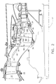
- FIGS. 1 and 2 there is illustrated in FIGS. 1 and 2 a bypass turbofan gas turbine engine 10 having a generally longitudinally extending axis or centerline 12 generally extending in a forward direction 14 and an aft direction 16.
- the bypass turbofan engine 10 includes a core engine 18 (also called a gas generator) which includes a core driven fan (CDF) in 19, a high pressure compressor 20, a combustor 22, and a high pressure turbine (HPT) 23 having a row of high pressure turbine (HPT) blades 24, all arranged in a serial, axial flow relationship.
- a core engine 18 also called a gas generator
- CDF core driven fan
- HPT high pressure turbine
- HPT high pressure turbine
- High pressure compressor blades 64 of the high pressure compressor 20 and the CDF 19 are fixedly interconnected in driving engagement to the high pressure turbine blades 24 by a larger diameter annular core engine shaft 26 which is disposed coaxially about the centerline 12 of the engine 10 forming a high pressure spool or rotor 29.
- the core engine 18 is effective for generating combustion gases. Pressurized air from the high pressure compressor 20 is mixed with fuel in the combustor 22 and ignited, thereby, generating combustion gases. Some work is extracted from these gases by the high pressure turbine blades 24 which drives the high pressure compressor 20.
- the combustion gases are discharged from the core engine 18 into a power turbine or low pressure turbine (LPT) 27 having a row of low pressure turbine rotor (LPT) blades 28.
- the low pressure turbine rotor blades 28 are fixedly attached to a smaller diameter annular low pressure shaft 30 which is disposed coaxially about the centerline 12 of the engine 10 within the core engine shaft 26 forming a low pressure spool.
- the low pressure shaft 30 rotates a more longitudinally forward row of generally radially outwardly extending and circumferentially spaced-apart forward fan rotor blades 32 of a forward fan 33.
- the core engine shaft 26 also rotates a more longitudinally aft apart core driven or aft fan rotor blade assembly 36, in accordance with one embodiment of the present invention, having generally radially outwardly extending blade tips 38.
- the aft fan rotor blade assembly 36 is disposed longitudinally aft of the more longitudinally forward row of forward fan rotor blades 32.
- a row of circumferentially spaced-apart aft fan stator vanes 34 (attached at either or both radial ends) is disposed longitudinally between the forward fan 33 and the aft fan rotor assembly 36.
- a fan bypass duct 40 has a first inlet 42 disposed longitudinally between the forward fan 33 and the aft or core driven fan 19.
- the first inlet 42 includes a front selector valve door 44 and a first flow splitter 42A.
- a second inlet 46 to the fan bypass duct 40 is also disposed longitudinally between the forward fan 33 and the aft or core driven fan 19, thereby providing two parallel bypass flowpaths into the fan bypass duct from the forward fan.
- the fan bypass duct 40 is in fluid communication with a second inlet 46 by way of a second inlet duct 43 having a second inlet duct outlet 47 to the fan bypass duct 40.
- the second inlet 46 includes an annular duct wall 45 with a second flow splitter 48.
- the annular duct wall 45 includes a rotatable portion commonly referred to as a shroud 108 of the aft CDF 19. Annular seals 45S are provided between the rotatable shroud 108 of the annular duct wall 45 and adjacent stationary portions of the wall just forward and aft of it.
- FIG. 2 Illustrated in FIG. 2 is a more particular design of the engine 10 and CDF 19 illustrating the shroud 108 of the annular duct wall 45 that rotates with the high pressure spool.
- the second flow splitter 48 may be axially positioned forward of (denoted by the solid line) or proximate to (denoted by the dashed line) the first flow splitter 42A axial location depending on the particular aerodynamic considerations for a given engine.
- the radially outer airfoils 107 and radially inner airfoils 109 of blade assembly 37 have different airfoils with separate non-continuous profiles and leading and trailing edges LE and TE, respectively.
- the outer airfoils 107 may or may not be indexed, one to one, and generally aligned with the inner airfoils 109.
- the same construction may be also be applied to the radially outer vane tip portions 84 and the radially inner vane hub portions 86 of the fan vanes 34.
- the vane tip portion 84 may have an extended length pivotable trailing-edge tip flap 88 that extends aft of the trailing edge 121 of the independently pivotable trailing-edge inner flap 90 radially inner hub portion 86.
- the annular seals 45S cooperate with lands 138 of adjacent stationary portions of the wall 45.
- the shroud 108 is disposed radially between a radially outer row 116 of outer airfoils 107 and a radially inner row 111 of inner airfoils 109, respectively of the aft CDF 19.
- the annular duct wall 45 also includes a non-rotatable portion 106 that is disposed between, preferably variable angle, radially outer vane tip portions 84 and radially inner vane hub portions 86 of the fan vanes 34.
- Annular seals 45S are provided to prevent or inhibit leakage around the shroud 108.
- the seals 45S include axially spaced apart annular leading and trailing shroud edges 120 and 122 corresponding to leading and trailing airfoil edges LE and TE, respectively of the outer airfoils 107.
- Empty leading and trailing cavities 128 and 130 respectively extend axially into the shroud 108 from the leading and trailing shroud edges 120 and 122. This provides a means for reducing stresses in the leading and trailing airfoil edges LE and TE, respectively of the inner and outer airfoils 107 and the corresponding airfoil edges are located near the cavities.
- the cavities are structural voids that prevent or reduce centrifugal loads from being transmitted to the leading and trailing airfoil edges LE and TE, respectively of the inner and outer airfoils 109 and 107, respectively.
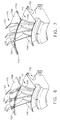
- FIGS. 3 and 4 illustrate, in more detail, a more particular embodiment of the present invention where the blade assembly 36 in the form of a blisk 132 having an annular hub or rim 140 disposed about a rotor axis which is centerline 12 and the blade assembly 36 is disposed around the rim.
- the shroud 108 is disposed radially between the radially outer row 116 of outer airfoils 107 and the radially inner row 111 of inner airfoils 109.
- the radially outer row 116 of outer airfoils 107 are integrally mounted to the rim 140.
- the leading and trailing cavities 128 and 130 are full 360 degree annular grooves 142 extending axially into the shroud 108 from the leading and trailing shroud edges 120 and 122.
- the grooves 142 extend axially under the leading and trailing airfoil edges LE and TE, respectively of the outer airfoils 107.
- the blisk of this invention is particularly useful as part of a rotor powered by the high pressure turbine HPT of an aircraft gas turbine engine.
- FIG. 5 illustrates another embodiment of the present invention in which the cavities are in the form of leading and trailing pluralities of circumferentially extending annular grooved pockets 146 extending axially into the shroud 108 from the leading and trailing shroud edges 120 and 122.
- the pockets 146 extend axially under the leading and trailing airfoil edges LE and TE, respectively of the outer airfoils 107.
- FIG. 6 illustrates another embodiment of the present invention in which the cavities are in the form of groups 148 of circumferentially canted holes 150 extending axially into the shroud 108 from the leading and trailing shroud edges 120 and 122.
- the holes 150 extend axially under the leading and trailing airfoil edges LE and TE, respectively of the outer airfoils 107.
- the holes 150 are substantially circumferentially aligned with a corresponding one of the leading and trailing airfoil edges LE and TE, respectively of the outer airfoils 107 and canted circumferentially in a direction from the corresponding outer airfoil leading to trailing edges.
- FIG. 7 illustrates another embodiment of the present invention in which the shroud 108 is segmented such as the one disclosed in U.S. Patent No. 5,562,419
- a friction damper can be designed to fit inside the groove, such as a wire damper, and used to damp both inner and outer airfoil vibratory modes.
- the present invention may also be used with segmented shrouds such as those disclosed in U.S. Patent No. 5,562,419.
- the annular seals 45S are illustrated as tongue and groove seals where the tongue is provided by annular knife edges on stationary portions of the annular duct wall 45 which are cooperatively disposed within the grooves 142.
- the seals for the embodiments having the grooved pockets (FIG. 5) and the canted holes (FIG. 6) use either abutting edges, overlapping edges, or some other kind of sealing means that are well known in the field such as shiplap seals.
Landscapes
- Engineering & Computer Science (AREA)
- Mechanical Engineering (AREA)
- General Engineering & Computer Science (AREA)
- Physics & Mathematics (AREA)
- Fluid Mechanics (AREA)
- Ceramic Engineering (AREA)
- Structures Of Non-Positive Displacement Pumps (AREA)
- Turbine Rotor Nozzle Sealing (AREA)
Applications Claiming Priority (2)
| Application Number | Priority Date | Filing Date | Title |
|---|---|---|---|
| US08/925,345 US5988980A (en) | 1997-09-08 | 1997-09-08 | Blade assembly with splitter shroud |
| US925345 | 1997-09-08 |
Publications (3)
| Publication Number | Publication Date |
|---|---|
| EP0900920A2 true EP0900920A2 (de) | 1999-03-10 |
| EP0900920A3 EP0900920A3 (de) | 2000-03-22 |
| EP0900920B1 EP0900920B1 (de) | 2007-08-08 |
Family
ID=25451593
Family Applications (1)
| Application Number | Title | Priority Date | Filing Date |
|---|---|---|---|
| EP98305524A Expired - Lifetime EP0900920B1 (de) | 1997-09-08 | 1998-07-10 | Einteiliger Blisk einer Gasturbine |
Country Status (4)
| Country | Link |
|---|---|
| US (1) | US5988980A (de) |
| EP (1) | EP0900920B1 (de) |
| JP (1) | JP4368435B2 (de) |
| DE (1) | DE69838201T2 (de) |
Cited By (13)
| Publication number | Priority date | Publication date | Assignee | Title |
|---|---|---|---|---|
| GB2353826A (en) * | 1999-08-30 | 2001-03-07 | Mtu Muenchen Gmbh | Aerofoil to platform transition in gas turbine blade/vane |
| GB2380527A (en) * | 2001-08-11 | 2003-04-09 | Rolls Royce Plc | Gas turbine engine guide vane assembly with noise reduction |
| EP1087100A3 (de) * | 1999-09-23 | 2004-01-02 | General Electric Company | Kompressorrotor- Konfiguration |
| EP1914384A2 (de) * | 2006-10-12 | 2008-04-23 | General Electric Company | Fan mit einheitigen Schaufeln, Band und Rotorscheibe |
| US7500352B2 (en) | 2004-05-28 | 2009-03-10 | Rolls-Royce Plc | Gas turbine engine |
| WO2011161033A1 (de) | 2010-06-22 | 2011-12-29 | Bayer Materialscience Ag | Verfahren zur herstellung von flächigen, hydrophilen, aliphatischen polyurethan-schäumen |
| US8347633B2 (en) | 2007-07-27 | 2013-01-08 | United Technologies Corporation | Gas turbine engine with variable geometry fan exit guide vane system |
| US8459035B2 (en) | 2007-07-27 | 2013-06-11 | United Technologies Corporation | Gas turbine engine with low fan pressure ratio |
| EP1895142A3 (de) * | 2006-07-31 | 2014-04-09 | General Electric Company | Flade Bläser mit verschiedenen inneren und äußeren Staffelungswinkeln der Schaufeln ober und unterhalb des dazwischen befindlichen Deckbandes |
| WO2014143305A1 (en) * | 2013-03-14 | 2014-09-18 | United Technologies Corporation | Low speed fan for gas turbine engines |
| WO2015049548A1 (en) * | 2013-10-03 | 2015-04-09 | Franco Tosi Meccanica S.P.A. | Rotor stage of axial turbine with improved chord/pitch ratio |
| US9932846B2 (en) | 2012-11-22 | 2018-04-03 | Rolls-Royce Deutschland Ltd & Co Kg | Aeroengine sealing arrangement |
| US12037921B2 (en) | 2022-08-04 | 2024-07-16 | General Electric Company | Fan for a turbine engine |
Families Citing this family (45)
| Publication number | Priority date | Publication date | Assignee | Title |
|---|---|---|---|---|
| US6454535B1 (en) * | 2000-10-31 | 2002-09-24 | General Electric Company | Blisk |
| MY140707A (en) * | 2002-02-28 | 2010-01-15 | Mitsubishi Tanabe Pharma Corp | Process for preparing a phenylalanine derivative and intermediates thereof |
| US6902376B2 (en) * | 2002-12-26 | 2005-06-07 | General Electric Company | Compressor blade with dovetail slotted to reduce stress on the airfoil leading edge |
| US7121803B2 (en) * | 2002-12-26 | 2006-10-17 | General Electric Company | Compressor blade with dovetail slotted to reduce stress on the airfoil leading edge |
| US6761536B1 (en) * | 2003-01-31 | 2004-07-13 | Power Systems Mfg, Llc | Turbine blade platform trailing edge undercut |
| US6901739B2 (en) * | 2003-10-07 | 2005-06-07 | General Electric Company | Gas turbine engine with variable pressure ratio fan system |
| CN100362225C (zh) * | 2005-06-30 | 2008-01-16 | 北京航空航天大学 | 微型单叶轮涡轮风扇发动机 |
| US7603839B2 (en) * | 2005-12-22 | 2009-10-20 | Pratt & Whitney Canada Corp. | Scavenge pump system and method |
| US7578655B1 (en) * | 2006-05-20 | 2009-08-25 | Florida Turbine Technologies, Inc. | Composite gas turbine fan blade |
| US7594799B2 (en) * | 2006-09-13 | 2009-09-29 | General Electric Company | Undercut fillet radius for blade dovetails |
| US8333559B2 (en) * | 2007-04-03 | 2012-12-18 | Carrier Corporation | Outlet guide vanes for axial flow fans |
| US8141366B2 (en) * | 2008-08-19 | 2012-03-27 | United Technologies Corporation | Gas turbine engine with variable area fan nozzle |
| US8485784B2 (en) * | 2009-07-14 | 2013-07-16 | General Electric Company | Turbine bucket lockwire rotation prevention |
| US20110167784A1 (en) * | 2009-09-25 | 2011-07-14 | James Edward Johnson | Method of operating a convertible fan engine |
| US20110167792A1 (en) * | 2009-09-25 | 2011-07-14 | James Edward Johnson | Adaptive engine |
| US8435006B2 (en) * | 2009-09-30 | 2013-05-07 | Rolls-Royce Corporation | Fan |
| US20110120083A1 (en) * | 2009-11-20 | 2011-05-26 | Rollin George Giffin | Gas turbine engine with outer fans |
| US8695324B2 (en) * | 2009-11-20 | 2014-04-15 | General Electric Co. | Multistage tip fan |
| US20110120078A1 (en) * | 2009-11-24 | 2011-05-26 | Schwark Jr Fred W | Variable area fan nozzle track |
| US8443586B2 (en) * | 2009-11-24 | 2013-05-21 | United Technologies Corporation | Variable area fan nozzle bearing track |
| US20110150627A1 (en) * | 2009-12-21 | 2011-06-23 | John Lewis Baughman | Method of operating a fan system |
| US8777554B2 (en) * | 2009-12-21 | 2014-07-15 | General Electric Company | Intermediate fan stage |
| CA2724610C (en) * | 2009-12-21 | 2018-01-23 | General Electric Company | Intermediate fan stage |
| US8459943B2 (en) * | 2010-03-10 | 2013-06-11 | United Technologies Corporation | Gas turbine engine rotor sections held together by tie shaft, and with blade rim undercut |
| PL217698B1 (pl) * | 2010-07-28 | 2014-08-29 | Gen Electric | Sposób naprawiania metalowego elementu składowego turbiny i metalowy element składowy turbiny |
| US9297311B2 (en) * | 2011-03-22 | 2016-03-29 | Alstom Technology Ltd | Gas turbine power plant with flue gas recirculation and oxygen-depleted cooling gas |
| US8998588B2 (en) * | 2011-08-18 | 2015-04-07 | General Electric Company | Segmented fan assembly |
| EP2971656B1 (de) | 2013-03-15 | 2020-03-04 | United Technologies Corporation | Aerodynamische schienenverkleidung für die lüftungsgondel eines gasturbinenmotors |
| WO2014168743A1 (en) * | 2013-04-12 | 2014-10-16 | United Technologies Corporation | Integrally bladed rotor |
| WO2015077011A1 (en) | 2013-11-19 | 2015-05-28 | United Technologies Corporation | Multi-element inner shroud extension for a turbo-machine |
| WO2016189712A1 (ja) * | 2015-05-27 | 2016-12-01 | 株式会社Ihi | ジェットエンジン |
| US10280872B2 (en) * | 2015-08-27 | 2019-05-07 | Rolls-Royce North American Technologies Inc. | System and method for a fluidic barrier from the upstream splitter |
| US10563593B2 (en) * | 2016-01-04 | 2020-02-18 | Rolls-Royce North American Technologies, Inc. | System and method of transferring power in a gas turbine engine |
| FR3048015B1 (fr) * | 2016-02-19 | 2020-03-06 | Safran Aircraft Engines | Aube de turbomachine, comprenant un pied aux concentrations de contrainte reduites |
| US10563516B2 (en) * | 2016-07-06 | 2020-02-18 | General Electric Company | Turbine engine and method of assembling |
| US11085309B2 (en) | 2017-09-22 | 2021-08-10 | General Electric Company | Outer drum rotor assembly |
| US11401862B2 (en) * | 2018-07-23 | 2022-08-02 | Raytheon Technologies Corporation | Stator configuration for gas turbine engine |
| US12044167B2 (en) | 2018-07-23 | 2024-07-23 | Rtx Corporation | Stator configuration for gas turbine engine |
| US10920617B2 (en) | 2018-08-17 | 2021-02-16 | Raytheon Technologies Corporation | Gas turbine engine seal ring assembly |
| US11149651B2 (en) | 2019-08-07 | 2021-10-19 | Raytheon Technologies Corporation | Seal ring assembly for a gas turbine engine |
| US11060406B2 (en) * | 2019-10-11 | 2021-07-13 | Pratt & Whitney Canada Corp. | Rotor for gas turbine engine |
| US11149552B2 (en) * | 2019-12-13 | 2021-10-19 | General Electric Company | Shroud for splitter and rotor airfoils of a fan for a gas turbine engine |
| US11428160B2 (en) | 2020-12-31 | 2022-08-30 | General Electric Company | Gas turbine engine with interdigitated turbine and gear assembly |
| CN115523054A (zh) * | 2022-10-13 | 2022-12-27 | 中国航发湖南动力机械研究所 | 一种内外涵导叶可调的双流道风扇结构及航空发动机 |
| US20240286757A1 (en) * | 2023-02-23 | 2024-08-29 | ESS 2 Tech, LLC | Fluid accelerator |
Citations (4)
| Publication number | Priority date | Publication date | Assignee | Title |
|---|---|---|---|---|
| US4068471A (en) | 1975-06-16 | 1978-01-17 | General Electric Company | Variable cycle engine with split fan section |
| US5402638A (en) | 1993-10-04 | 1995-04-04 | General Electric Company | Spillage drag reducing flade engine |
| US5404713A (en) | 1993-10-04 | 1995-04-11 | General Electric Company | Spillage drag and infrared reducing flade engine |
| US5562419A (en) | 1995-06-06 | 1996-10-08 | General Electric Company | Shrouded fan blisk |
Family Cites Families (17)
| Publication number | Priority date | Publication date | Assignee | Title |
|---|---|---|---|---|
| US1544318A (en) * | 1923-09-12 | 1925-06-30 | Westinghouse Electric & Mfg Co | Turbine-blade lashing |
| US2007408A (en) * | 1932-03-26 | 1935-07-09 | C S Engineering Co | Turbine |
| GB585331A (en) * | 1941-04-15 | 1947-02-05 | Alan Arnold Griffith | Improvements in or relating to internal-combustion turbines |
| GB586552A (en) * | 1941-11-01 | 1947-03-24 | Karl Baumann | Improvements in or relating to internal combustion turbine plant |
| US2999631A (en) * | 1958-09-05 | 1961-09-12 | Gen Electric | Dual airfoil |
| US3262635A (en) * | 1964-11-06 | 1966-07-26 | Gen Electric | Turbomachine sealing means |
| US3385064A (en) * | 1966-01-07 | 1968-05-28 | Rolls Royce | Gas turbine engine |
| FR1555814A (de) * | 1967-12-12 | 1969-01-31 | ||
| DE2007810A1 (de) * | 1969-03-31 | 1970-10-08 | Nordisk Ventilator Co. A/S, Naestved (Dänemark) | Doppelter Läufer für Axialgebläse |
| US3610776A (en) * | 1970-03-02 | 1971-10-05 | Rolls Royce | Compressor blade for a gas turbine engine |
| FR2141435B1 (de) * | 1971-06-02 | 1973-06-29 | Snecma | |
| SU612056A1 (ru) * | 1977-03-09 | 1978-06-25 | Предприятие П/Я А-3513 | Двухъ русна рабоча лопатка турбомашины |
| US4791783A (en) * | 1981-11-27 | 1988-12-20 | General Electric Company | Convertible aircraft engine |
| CH660207A5 (en) * | 1983-06-29 | 1987-03-31 | Bbc Brown Boveri & Cie | Device for the damping of blade vibrations in axial flow turbo engines |
| US4595340A (en) * | 1984-07-30 | 1986-06-17 | General Electric Company | Gas turbine bladed disk assembly |
| US5201850A (en) * | 1991-02-15 | 1993-04-13 | General Electric Company | Rotor tip shroud damper including damper wires |
| US5261227A (en) * | 1992-11-24 | 1993-11-16 | General Electric Company | Variable specific thrust turbofan engine |
-
1997
- 1997-09-08 US US08/925,345 patent/US5988980A/en not_active Expired - Lifetime
-
1998
- 1998-07-10 DE DE69838201T patent/DE69838201T2/de not_active Expired - Lifetime
- 1998-07-10 EP EP98305524A patent/EP0900920B1/de not_active Expired - Lifetime
- 1998-07-24 JP JP20936198A patent/JP4368435B2/ja not_active Expired - Lifetime
Patent Citations (4)
| Publication number | Priority date | Publication date | Assignee | Title |
|---|---|---|---|---|
| US4068471A (en) | 1975-06-16 | 1978-01-17 | General Electric Company | Variable cycle engine with split fan section |
| US5402638A (en) | 1993-10-04 | 1995-04-04 | General Electric Company | Spillage drag reducing flade engine |
| US5404713A (en) | 1993-10-04 | 1995-04-11 | General Electric Company | Spillage drag and infrared reducing flade engine |
| US5562419A (en) | 1995-06-06 | 1996-10-08 | General Electric Company | Shrouded fan blisk |
Cited By (19)
| Publication number | Priority date | Publication date | Assignee | Title |
|---|---|---|---|---|
| GB2353826A (en) * | 1999-08-30 | 2001-03-07 | Mtu Muenchen Gmbh | Aerofoil to platform transition in gas turbine blade/vane |
| US6478539B1 (en) | 1999-08-30 | 2002-11-12 | Mtu Aero Engines Gmbh | Blade structure for a gas turbine engine |
| GB2353826B (en) * | 1999-08-30 | 2003-07-23 | Mtu Muenchen Gmbh | Blade ring for a gas turbine |
| EP1087100A3 (de) * | 1999-09-23 | 2004-01-02 | General Electric Company | Kompressorrotor- Konfiguration |
| GB2380527A (en) * | 2001-08-11 | 2003-04-09 | Rolls Royce Plc | Gas turbine engine guide vane assembly with noise reduction |
| US6764276B2 (en) | 2001-08-11 | 2004-07-20 | Rolls-Royce Plc | Guide vane assembly |
| GB2380527B (en) * | 2001-08-11 | 2004-10-27 | Rolls Royce Plc | A guide vane assembly |
| US7500352B2 (en) | 2004-05-28 | 2009-03-10 | Rolls-Royce Plc | Gas turbine engine |
| EP1895142A3 (de) * | 2006-07-31 | 2014-04-09 | General Electric Company | Flade Bläser mit verschiedenen inneren und äußeren Staffelungswinkeln der Schaufeln ober und unterhalb des dazwischen befindlichen Deckbandes |
| EP1914384A2 (de) * | 2006-10-12 | 2008-04-23 | General Electric Company | Fan mit einheitigen Schaufeln, Band und Rotorscheibe |
| EP1914384A3 (de) * | 2006-10-12 | 2011-12-14 | General Electric Company | Fan mit einheitigen Schaufeln, Band und Rotorscheibe |
| US8347633B2 (en) | 2007-07-27 | 2013-01-08 | United Technologies Corporation | Gas turbine engine with variable geometry fan exit guide vane system |
| US8459035B2 (en) | 2007-07-27 | 2013-06-11 | United Technologies Corporation | Gas turbine engine with low fan pressure ratio |
| WO2011161033A1 (de) | 2010-06-22 | 2011-12-29 | Bayer Materialscience Ag | Verfahren zur herstellung von flächigen, hydrophilen, aliphatischen polyurethan-schäumen |
| US9932846B2 (en) | 2012-11-22 | 2018-04-03 | Rolls-Royce Deutschland Ltd & Co Kg | Aeroengine sealing arrangement |
| WO2014143305A1 (en) * | 2013-03-14 | 2014-09-18 | United Technologies Corporation | Low speed fan for gas turbine engines |
| US11156090B2 (en) | 2013-03-14 | 2021-10-26 | Raytheon Technologies Corporation | Low speed fan for gas turbine engines |
| WO2015049548A1 (en) * | 2013-10-03 | 2015-04-09 | Franco Tosi Meccanica S.P.A. | Rotor stage of axial turbine with improved chord/pitch ratio |
| US12037921B2 (en) | 2022-08-04 | 2024-07-16 | General Electric Company | Fan for a turbine engine |
Also Published As
| Publication number | Publication date |
|---|---|
| DE69838201T2 (de) | 2008-05-08 |
| JPH1193604A (ja) | 1999-04-06 |
| DE69838201D1 (de) | 2007-09-20 |
| EP0900920B1 (de) | 2007-08-08 |
| US5988980A (en) | 1999-11-23 |
| EP0900920A3 (de) | 2000-03-22 |
| JP4368435B2 (ja) | 2009-11-18 |
Similar Documents
| Publication | Publication Date | Title |
|---|---|---|
| EP0900920B1 (de) | Einteiliger Blisk einer Gasturbine | |
| CA2333843C (en) | Fluted compressor flowpath | |
| EP2871322B1 (de) | Rotornabe für einen Turbinenmotor | |
| CA1233325A (en) | Counter rotation power turbine | |
| US5607284A (en) | Baffled passage casing treatment for compressor blades | |
| CN109538352B (zh) | 外鼓转子组件和燃气涡轮发动机 | |
| EP0643199B1 (de) | Rotorschaufel | |
| US20140260326A1 (en) | Geared turbofan engine with high compressor exit temperature | |
| EP3084139B1 (de) | Integral beschaufelter rotor eines gasturbinenmotor mit asymmetrischen grabenfillets | |
| EP3656979B1 (de) | Schaufel mit stagnationszonenkühlung | |
| CN109477391B (zh) | 涡扇发动机及对应的操作方法 | |
| EP3875733B1 (de) | Schaufelanordnung für gasturbinenmotor | |
| EP3056685B1 (de) | Statorschaufel mit plattform mit schräger fläche | |
| EP1944468A2 (de) | Gasturbinenschaufel | |
| US20220220854A1 (en) | Turbine engine with an airfoil having a set of dimples | |
| US11248467B2 (en) | Fan blade | |
| US10746098B2 (en) | Compressor rotor cooling apparatus | |
| GB2477745A (en) | Compressor Casing | |
| US11286784B2 (en) | Aerofoil assembly and method | |
| US10508548B2 (en) | Turbine engine with a platform cooling circuit | |
| US20220090504A1 (en) | Rotor blade for a gas turbine engine having a metallic structural member and a composite fairing | |
| US11739643B2 (en) | Method and apparatus for cooling a portion of a counter-rotating turbine engine | |
| EP3056686B1 (de) | Rotor mit axialem arm mit hervorstehender rampe | |
| CN118896074A (zh) | 高压压缩机的前向负载减少结构 | |
| GB2581351A (en) | Blade for a gas turbine engine |
Legal Events
| Date | Code | Title | Description |
|---|---|---|---|
| PUAI | Public reference made under article 153(3) epc to a published international application that has entered the european phase |
Free format text: ORIGINAL CODE: 0009012 |
|
| AK | Designated contracting states |
Kind code of ref document: A2 Designated state(s): DE FR GB IT |
|
| AX | Request for extension of the european patent |
Free format text: AL;LT;LV;MK;RO;SI |
|
| PUAL | Search report despatched |
Free format text: ORIGINAL CODE: 0009013 |
|
| RIC1 | Information provided on ipc code assigned before grant |
Free format text: 7F 01D 11/00 A, 7F 01D 5/14 B, 7F 01D 5/22 B |
|
| AK | Designated contracting states |
Kind code of ref document: A3 Designated state(s): AT BE CH CY DE DK ES FI FR GB GR IE IT LI LU MC NL PT SE |
|
| AX | Request for extension of the european patent |
Free format text: AL;LT;LV;MK;RO;SI |
|
| 17P | Request for examination filed |
Effective date: 20000922 |
|
| AKX | Designation fees paid |
Free format text: DE FR GB IT |
|
| 17Q | First examination report despatched |
Effective date: 20020410 |
|
| GRAP | Despatch of communication of intention to grant a patent |
Free format text: ORIGINAL CODE: EPIDOSNIGR1 |
|
| RTI1 | Title (correction) |
Free format text: ONE-PIECE BLISK OF A GAS TURBINE ENGINE |
|
| GRAS | Grant fee paid |
Free format text: ORIGINAL CODE: EPIDOSNIGR3 |
|
| GRAA | (expected) grant |
Free format text: ORIGINAL CODE: 0009210 |
|
| AK | Designated contracting states |
Kind code of ref document: B1 Designated state(s): DE FR GB IT |
|
| REG | Reference to a national code |
Ref country code: GB Ref legal event code: FG4D |
|
| REF | Corresponds to: |
Ref document number: 69838201 Country of ref document: DE Date of ref document: 20070920 Kind code of ref document: P |
|
| ET | Fr: translation filed | ||
| PLBE | No opposition filed within time limit |
Free format text: ORIGINAL CODE: 0009261 |
|
| STAA | Information on the status of an ep patent application or granted ep patent |
Free format text: STATUS: NO OPPOSITION FILED WITHIN TIME LIMIT |
|
| 26N | No opposition filed |
Effective date: 20080509 |
|
| REG | Reference to a national code |
Ref country code: FR Ref legal event code: PLFP Year of fee payment: 19 |
|
| PGFP | Annual fee paid to national office [announced via postgrant information from national office to epo] |
Ref country code: DE Payment date: 20160726 Year of fee payment: 19 Ref country code: IT Payment date: 20160722 Year of fee payment: 19 Ref country code: GB Payment date: 20160727 Year of fee payment: 19 |
|
| PGFP | Annual fee paid to national office [announced via postgrant information from national office to epo] |
Ref country code: FR Payment date: 20160726 Year of fee payment: 19 |
|
| REG | Reference to a national code |
Ref country code: DE Ref legal event code: R119 Ref document number: 69838201 Country of ref document: DE |
|
| GBPC | Gb: european patent ceased through non-payment of renewal fee |
Effective date: 20170710 |
|
| REG | Reference to a national code |
Ref country code: FR Ref legal event code: ST Effective date: 20180330 |
|
| PG25 | Lapsed in a contracting state [announced via postgrant information from national office to epo] |
Ref country code: GB Free format text: LAPSE BECAUSE OF NON-PAYMENT OF DUE FEES Effective date: 20170710 Ref country code: DE Free format text: LAPSE BECAUSE OF NON-PAYMENT OF DUE FEES Effective date: 20180201 |
|
| PG25 | Lapsed in a contracting state [announced via postgrant information from national office to epo] |
Ref country code: FR Free format text: LAPSE BECAUSE OF NON-PAYMENT OF DUE FEES Effective date: 20170731 |
|
| PG25 | Lapsed in a contracting state [announced via postgrant information from national office to epo] |
Ref country code: IT Free format text: LAPSE BECAUSE OF NON-PAYMENT OF DUE FEES Effective date: 20170710 |