EP0900918B1 - Verfahren und Anordnung zur Unterdrukkung von Schwingungen einer Bohrgestänge - Google Patents
Verfahren und Anordnung zur Unterdrukkung von Schwingungen einer Bohrgestänge Download PDFInfo
- Publication number
- EP0900918B1 EP0900918B1 EP98202492A EP98202492A EP0900918B1 EP 0900918 B1 EP0900918 B1 EP 0900918B1 EP 98202492 A EP98202492 A EP 98202492A EP 98202492 A EP98202492 A EP 98202492A EP 0900918 B1 EP0900918 B1 EP 0900918B1
- Authority
- EP
- European Patent Office
- Prior art keywords
- drillstring
- noise
- impedance
- sub
- acoustic
- Prior art date
- Legal status (The legal status is an assumption and is not a legal conclusion. Google has not performed a legal analysis and makes no representation as to the accuracy of the status listed.)
- Expired - Lifetime
Links
Images

Classifications
-
- E—FIXED CONSTRUCTIONS
- E21—EARTH OR ROCK DRILLING; MINING
- E21B—EARTH OR ROCK DRILLING; OBTAINING OIL, GAS, WATER, SOLUBLE OR MELTABLE MATERIALS OR A SLURRY OF MINERALS FROM WELLS
- E21B17/00—Drilling rods or pipes; Flexible drill strings; Kellies; Drill collars; Sucker rods; Cables; Casings; Tubings
- E21B17/006—Accessories for drilling pipes, e.g. cleaners
-
- E—FIXED CONSTRUCTIONS
- E21—EARTH OR ROCK DRILLING; MINING
- E21B—EARTH OR ROCK DRILLING; OBTAINING OIL, GAS, WATER, SOLUBLE OR MELTABLE MATERIALS OR A SLURRY OF MINERALS FROM WELLS
- E21B17/00—Drilling rods or pipes; Flexible drill strings; Kellies; Drill collars; Sucker rods; Cables; Casings; Tubings
- E21B17/02—Couplings; joints
- E21B17/04—Couplings; joints between rod or the like and bit or between rod and rod or the like
- E21B17/07—Telescoping joints for varying drill string lengths; Shock absorbers
-
- E—FIXED CONSTRUCTIONS
- E21—EARTH OR ROCK DRILLING; MINING
- E21B—EARTH OR ROCK DRILLING; OBTAINING OIL, GAS, WATER, SOLUBLE OR MELTABLE MATERIALS OR A SLURRY OF MINERALS FROM WELLS
- E21B47/00—Survey of boreholes or wells
- E21B47/01—Devices for supporting measuring instruments on drill bits, pipes, rods or wirelines; Protecting measuring instruments in boreholes against heat, shock, pressure or the like
- E21B47/017—Protecting measuring instruments
-
- E—FIXED CONSTRUCTIONS
- E21—EARTH OR ROCK DRILLING; MINING
- E21B—EARTH OR ROCK DRILLING; OBTAINING OIL, GAS, WATER, SOLUBLE OR MELTABLE MATERIALS OR A SLURRY OF MINERALS FROM WELLS
- E21B47/00—Survey of boreholes or wells
- E21B47/12—Means for transmitting measuring-signals or control signals from the well to the surface, or from the surface to the well, e.g. for logging while drilling
- E21B47/14—Means for transmitting measuring-signals or control signals from the well to the surface, or from the surface to the well, e.g. for logging while drilling using acoustic waves
- E21B47/16—Means for transmitting measuring-signals or control signals from the well to the surface, or from the surface to the well, e.g. for logging while drilling using acoustic waves through the drill string or casing, e.g. by torsional acoustic waves
-
- F—MECHANICAL ENGINEERING; LIGHTING; HEATING; WEAPONS; BLASTING
- F16—ENGINEERING ELEMENTS AND UNITS; GENERAL MEASURES FOR PRODUCING AND MAINTAINING EFFECTIVE FUNCTIONING OF MACHINES OR INSTALLATIONS; THERMAL INSULATION IN GENERAL
- F16F—SPRINGS; SHOCK-ABSORBERS; MEANS FOR DAMPING VIBRATION
- F16F15/00—Suppression of vibrations in systems; Means or arrangements for avoiding or reducing out-of-balance forces, e.g. due to motion
- F16F15/02—Suppression of vibrations of non-rotating, e.g. reciprocating systems; Suppression of vibrations of rotating systems by use of members not moving with the rotating systems
Definitions
- the present invention relates to apparatus and methods for reducing noise generated by elastic waves travelling through a tubular placed in a wellbore. More specifically, it relates to such noise reducing apparatus and methods for transmitting signals from a subterranean location to the surface using modulated elastic waves, preferably torsional waves.
- Background of the invention is the drilling of subterranean wells.
- Wells of the type commonly used for hydrocarbon or geothermal exploration are typically less than 30 cm (12 inches) in diameter and on the order of 2 to 8 km (1.5 to 5 miles) long.
- These wells are drilled using drillstrings assembled from relatively light sections (either 30 or 45 feet long) of drill pipe that are connected end-to-end by tool joints, additional sections being added to the uphole end as the hole deepens.
- the downhole end of the drillstring typically includes a drill collar, a weight assembled from sections of collar pipes with increasing diameter having an overall length on the order of 300 meters (1000 feet).
- a drill bit is attached to the downhole end of the drill collar, the weight of the collar causing the bit to bite into the earth as the drillstring is rotated from the surface.
- downhole mud motors or turbines are used to turn the bit.
- Drilling fluid is pumped from the surface to the drill bit through an axial hole in the drillstring. This fluid removes the cuttings from the hole, provides a hydrostatic head which controls the formation gases, provides a deposit on the wall to seal the formation, and sometimes provides cooling for the bit.
- MWD Measurement-While-Drilling
- LWD Logging-While-Drilling
- Various methods that have been tried for this communication include electromagnetic radiation through the ground formation, electrical transmission through an insulated conductor, pressure pulse propagation through the drilling mud, and acoustic wave propagation through the metal drillstring.
- Each of these methods has disadvantages associated with signal attenuation, ambient noise, high temperatures and compatibility with standard drilling procedures.
- This invention is directed towards the acoustical transmission of data through the metal drillstring.
- the history of such efforts is recorded in columns 2-4 of U.S. Pat. No.4,293,936, issued Oct 6, 1981, of Cox and Chancy.
- the first efforts were in the late 1940's by Sun Oil Company, which organization concluded there was too much attenuation in the drillstring for the technology at that time.
- the aforementioned Cox and Chancy patent concluded from their interpretation of the measured data obtained from a field test in a petroleum well that the Barnes model must be in error, because the centre of the passbands measured by Cox and Chancy did not agree with the predicted passbands of Barnes et al.
- the patent uses acoustic repeaters along the drillstring to ensure transmission of a particular frequency for a particular length of drill pipe to the surface.
- U.S. Patent No. 5,128,901, issued July 7, 1992, of D.S. Drumheller provides further apparatus and methods for transmitting data along a drillstring by use of a modulated continuous acoustical carrier wave centred within a passband of the drillstring. Noise is reduced by multiplying each frequency component of the signal by a factor which depended on the length of the drill pipe section. To eliminate the fine structure of the passbands, echoes are suppressed at each end of the drillstring employing an arrangement of magneto-strictive ring elements as transducers. The method is described to fail for shorter drillstrings with a length of below 3500 feet (1200 m).
- a hollow cylinder of composite material is attached to the outer surface of the drillstring.
- the cylinder is a stack of rings, which absorb elastic wave energy, cause multiple reflections, and disrupt the wave front of an elastic wave. It should be noted that the patent does not relate to the field of downhole data transmission.
- the United Kingdom Patent application GB 2311427 provides a mechanical filter to reduce transmission of longitudinal compressional waves along a drill string.
- the filter a section of tube having relatively compliant walls to which are attached one or more masses via springs.
- the masses act on the spring to provide high impedance points at particular frequencies.
- European Patent Application Publication No. 0 679 910 A2 discloses a tool for sonic logging while drilling.
- the transmitter is operated within a natural stop band of the drill collar.
- An imperforate stop band filter is also included between the transmitter and receiver to enhance the natural stop band.
- a basic feature of the present invention is to introduce in the drillstring impedance changes of particular sizes and spacing so as to deliberately create stopbands over particular frequency ranges in order to suppress noise in these frequency ranges.
- a preferred location for introducing the impedance changes is situated between the drill bit and any device which has to be protected from noise in particular frequency ranges.
- the device could be a sensitive mechanical, hydraulical, or electrical unit.
- the device is a transducer section which generates telemetry signals or a downhole drillstring sensor. With the transducer section operating in at least one of the created stopbands, noise arising from the drilling process is effectively cancelled from the transmitted signals.
- the impedance changes are preferably introduced by means of a baffle sub, i.e., a specifically designed part of the drillstring. It is preferred to avoid introducing moving parts into the drillstring. Therefore, in a preferred embodiment of the invention the baffle sub has no parts which move relatively to adjacent parts of the sub. Hence no drilling fluid or debris can enter between moving parts of the baffle and cause friction or other undesired effects.
- the width, depth and position of the stop band created by the baffle sub depend upon its geometry, and the drillstring it is connected to. In general, to move the stop band to a lower frequency requires the sub to be longer.
- the depth of the stop band depends upon both the length of the sub and the size of the impedance contrasts.
- the impedance contrasts depend upon the ratios of the polar moments of inertia of the different sections of the sub, which are proportional to the radii raised to the power 4.
- the impedance contrasts depend upon the ratios of the cross sectional areas of the sub sections, which are proportional to the radii squared.
- the impedance changes are generated by introducing a metal sub of essentially cylindrical shape into the drillstring.
- the inner diameter of the sub is constant, its outer diameter varies along the longitudinal axis of the cylinder.
- the energy which is unable to pass the baffle sub is reflected back towards the bit.
- the invention is based on based on the known analysis of wave energy travelling through the drillstring as described for example by D.S. Drumheller in: "The Propagation of Sound Waves in drillstrings", J. Acoust. Soc. Am., Vol. 97, pp. 2116-2125.
- Wave energy can travel along the drillstring as axial or torsional stress waves.
- the periodic structure of the drillstring gives rise to a band structure leaving distinct frequency bands for energy transmission (passbands) while suppressing energy in other frequency ranges (stopbands).
- the analysis further shows that the passbands have a fine structure which however is of no concern for the present application.
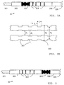
- the drillstring comprises several sections-including a 780 m long section of 5 inch 19.5 lb/ft drill pipe 101, followed by 112 m of 5 inch 50 lb/ft heavy wall drill pipe 102, 100 m of 6 inch drill collar 103 and finally a 100 m long section of 8 inch drill collar 104 terminated by the drill bit 105.
- the internal structure of the drillstring gives rise to a transmission response as depicted in FIG. 2.
- a similar response spectrum can be derived for other wave forms (e.g. axial waves).
- the transmission response of the drillstring signal transmission should be possible in the frequency ranges 0 to 120 Hz (first passband), 180 to 260 Hz (second passband) and above 370 Hz (third passband). Further passband are not considered in the present example but could equally be employed for signal transmission.
- baffle sub 303 in accordance with the invention is shown.
- the baffle sub 303 is part of the bottom hole assembly (BHA) 30, located near the end of the 8 inch drill collar section between the signal transmission unit 302 and several measurement-while-drilling (MWD) units 304.
- the BHA further comprises drill collars 305 and the drill bit 306.
- the location of the baffle sub is chosen such that during drilling operation the transmission unit 302 is, with respect to the passband used for signal transmission, acoustically isolated from noise stemming from drill bit. More specifically, the baffle sub generates a stopband which at least partly overlaps with the passband used for signal transmission.
- the baffle design is apparently dominated by four parameters: the size of the impedance contrasts, the ratio of lengths of the sections with high and low impedance (e.g. thick and thin sections), the absolute length of either of these sections, and the total length of the apparatus or baffle sub.
- the depth of the stopband thus generated is controlled by the size of the impedance contrast between the thick and thin sections. As the depth of the stopband increases with the impedance contrast, it can be seen as a first design rule to make this contrast as large as possible.
- the freedom to increase the impedance contrast is limited by maximal outer diameter of the drill collar, which is controlled by the well dimension, and its minimal inner diameter, which is limited by the required strength. The absolute values of these limits vary in dependence of well parameters and the material or materials (in case of a composite material)of the sub.
- the depth of the stopband also increases as the overall length of the sub increases, leading to a second design rule.
- the width and position of the stopband(s) is best controlled by using either the absolute width(s) of the section(s) with high or low impedance, respectively, or a ratio of the widths of the section(s) or a combination of both methods.
- the positions of the stopbands can be calculated for a periodic structure using for example the method taught by T.G. Barnes and B.R. Kirkwood in: Passbands for Acoustic Transmission in an Idealized Drill String, J.Acoustic.Soc.Am. Vol. 51(2), pp.1606-1608.
- the lengths l 1 and l 2 denote the lengths of the two section with different impedance, and the radii r i denote inner and outer radius of the two sections, respectively (for details see FIG. 3B).
- Stopbands occur when
- FIG. 3B details of the baffle sub 303 are shown in FIG. 3B.
- the total length of the sub is 20 m.
- Four circumferential grooves 307 are cut into the outer surface of the sub.
- the grooves have a uniform depth of approximately two inches (5 mm).
- the width, i.e. l 1 , of the grooves and their mutual distance (l 2 ) is four meters.
- the inner radii (i.e. r 0 and r 1 ) in the given example are equal (4 cm), although in general they might differ as indicated in FIG. 3B.
- the location of the stopband is controlled by the width of the grooves and the distance between two adjacent grooves. For some applications, it may be advantageous to fill the grooves with an epoxy resin.
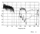
- the shape of the transmission response alters. This effect is illustrated by FIG. 4, which compares the original response function 40 with the new response function 41. Notably, the second passband is reduced on average by approximately 30 dB.
- FIG. 5 there is shown an arrangement 50 more suitable for look-ahead seismic measurements.
- the baffle sub 503 is located between the drill bit 506 and the MWD section 504 so that acoustic energy reflected from the formation and detected using receivers within the MWD section is not contaminated by acoustic noise travelling along the drillstring.
Landscapes
- Engineering & Computer Science (AREA)
- Physics & Mathematics (AREA)
- Mining & Mineral Resources (AREA)
- Life Sciences & Earth Sciences (AREA)
- Geology (AREA)
- Geochemistry & Mineralogy (AREA)
- General Life Sciences & Earth Sciences (AREA)
- Environmental & Geological Engineering (AREA)
- Fluid Mechanics (AREA)
- Mechanical Engineering (AREA)
- Acoustics & Sound (AREA)
- Geophysics (AREA)
- General Engineering & Computer Science (AREA)
- Remote Sensing (AREA)
- Aviation & Aerospace Engineering (AREA)
- Earth Drilling (AREA)
- Vibration Prevention Devices (AREA)
- Geophysics And Detection Of Objects (AREA)
Claims (9)
- Verfahren zum Isolieren einer Vorrichtung (302) vor einer Schallgeräuschquelle (306) in einem Bohrstrang (30), wobei das Verfahren den Schritt des Einführens eines Geräuschisolationsabschnitts (303) zwischen die Vorrichtung (302) und die Schallschwingungsquelle (306) umfaßt, wobei der Geräuschisolationsabschnitt (303) benachbarte Zonen mit unterschiedlicher Schallimpedanz aufweist, so daß die Geräuschausbreitung wenigstens in einem vorgegebenen Frequenzband unterdrückt wird, dadurch gekennzeichnet, daß die Vorrichtung (302) eine Telemetrieeinheit zum Senden und/oder Empfangen von Signalen von und/oder zu einem weiteren Ort durch den Metallbohrstrang ist.
- Verfahren nach Anspruch 1, bei dem die Vorrichtung im Betrieb Torsionswellen verwendet, um ein Signal von und/oder zu dem anderen Ort zu senden/empfangen.
- Verfahren nach Anspruch 1, bei dem der Isolationsabschnitt eine zylindrische Basis mit benachbarten Zonen mit unterschiedlicher Wanddicke umfaßt.
- Vorrichtung (303) zum Isolieren einer Vorrichtung (302) von einer Schallgeräuschquelle (306) in einem Bohrstrang (30), wobei die Vorrichtung (303) benachbarte Zonen mit unterschiedlicher Schallimpedanz umfaßt, derart, daß die Geräuschausbreitung wenigstens in einem vorgegebenen Frequenzband unterdrückt wird, dadurch gekennzeichnet, daß die Vorrichtung (302) eine Telemetrieeinheit zum Senden und/oder Empfangen von Signalen von und/oder zu dem anderen Ort durch den Metallbohrstrang ist.
- Vorrichtung nach Anspruch 4, bei der durch Zonen unterschiedlicher Dicke benachbarte Zonen unterschiedlicher Impedanz erzeugt werden.
- Vorrichtung nach Anspruch 4, bei der durch Zonen, die unterschiedliche Materialien aufweisen, benachbarte Zonen unterschiedlicher impedanz erzeugt werden.
- Vorrichtung nach Anspruch 4, bei der die Zonen periodisch angeordnet sind.
- Vorrichtung nach Anspruch 4, die ferner einen zylindrischen Körper aus Stahl mit einem periodischen Nutmuster umfaßt.
- Vorrichtung nach Anspruch 8, bei der die Nuten mit einem zweiten Material gefüllt sind, um einen gleichmäßigen inneren und äußeren Durchmesser des zylindrischen Körpers aus Stahl aufrechtzuerhalten.
Applications Claiming Priority (2)
| Application Number | Priority Date | Filing Date | Title |
|---|---|---|---|
| GB9716825A GB2327957A (en) | 1997-08-09 | 1997-08-09 | Method and apparatus for suppressing drillstring vibrations |
| GB9716825 | 1997-08-09 |
Publications (3)
| Publication Number | Publication Date |
|---|---|
| EP0900918A2 EP0900918A2 (de) | 1999-03-10 |
| EP0900918A3 EP0900918A3 (de) | 2001-09-12 |
| EP0900918B1 true EP0900918B1 (de) | 2003-11-05 |
Family
ID=10817214
Family Applications (1)
| Application Number | Title | Priority Date | Filing Date |
|---|---|---|---|
| EP98202492A Expired - Lifetime EP0900918B1 (de) | 1997-08-09 | 1998-07-24 | Verfahren und Anordnung zur Unterdrukkung von Schwingungen einer Bohrgestänge |
Country Status (6)
| Country | Link |
|---|---|
| US (1) | US6535458B2 (de) |
| EP (1) | EP0900918B1 (de) |
| CA (1) | CA2244558C (de) |
| DK (1) | DK0900918T3 (de) |
| GB (1) | GB2327957A (de) |
| NO (1) | NO317679B1 (de) |
Cited By (2)
| Publication number | Priority date | Publication date | Assignee | Title |
|---|---|---|---|---|
| US8042623B2 (en) | 2008-03-17 | 2011-10-25 | Baker Hughes Incorporated | Distributed sensors-controller for active vibration damping from surface |
| DE102010047568A1 (de) * | 2010-04-12 | 2011-12-15 | Peter Jantz | Einrichtung zur Übertragung von Informationen über Bohrgestänge |
Families Citing this family (30)
| Publication number | Priority date | Publication date | Assignee | Title |
|---|---|---|---|---|
| US6915875B2 (en) | 1999-06-03 | 2005-07-12 | Baker Hughes Incorporated | Acoustic isolator for downhole applications |
| US6615949B1 (en) * | 1999-06-03 | 2003-09-09 | Baker Hughes Incorporated | Acoustic isolator for downhole applications |
| US7028806B2 (en) * | 1999-06-03 | 2006-04-18 | Baker Hughes Incorporated | Acoustic isolator for downhole applications |
| GB2357527B (en) * | 1999-12-22 | 2002-07-17 | Schlumberger Holdings | System and method for torsional telemetry in a wellbore |
| GB0130291D0 (en) * | 2001-12-18 | 2002-02-06 | Schlumberger Holdings | Drill string telemetry system |
| US6940420B2 (en) | 2001-12-18 | 2005-09-06 | Schlumberger Technology Corporation | Drill string telemetry system |
| US6820716B2 (en) * | 2003-01-16 | 2004-11-23 | Baker Hughes Incorporated | Acoustic isolator for well logging system |
| US7513147B2 (en) * | 2003-07-03 | 2009-04-07 | Pathfinder Energy Services, Inc. | Piezocomposite transducer for a downhole measurement tool |
| US6995500B2 (en) * | 2003-07-03 | 2006-02-07 | Pathfinder Energy Services, Inc. | Composite backing layer for a downhole acoustic sensor |
| US7075215B2 (en) * | 2003-07-03 | 2006-07-11 | Pathfinder Energy Services, Inc. | Matching layer assembly for a downhole acoustic sensor |
| US7036363B2 (en) * | 2003-07-03 | 2006-05-02 | Pathfinder Energy Services, Inc. | Acoustic sensor for downhole measurement tool |
| US7334661B2 (en) * | 2004-02-05 | 2008-02-26 | Schlumberger Technology Corporation | Acoustic logging tool sleeve |
| US8270251B2 (en) * | 2005-12-05 | 2012-09-18 | Xact Downhole Telemetry Inc. | Acoustic isolator |
| CA2569818C (en) * | 2005-12-05 | 2013-08-13 | Xact Downhole Telemetry Inc. | Acoustic isolator |
| US7706213B2 (en) * | 2006-10-23 | 2010-04-27 | Nancy Ann Winfree | Mechanical filter for sensors |
| US7587936B2 (en) * | 2007-02-01 | 2009-09-15 | Smith International Inc. | Apparatus and method for determining drilling fluid acoustic properties |
| US20100133004A1 (en) * | 2008-12-03 | 2010-06-03 | Halliburton Energy Services, Inc. | System and Method for Verifying Perforating Gun Status Prior to Perforating a Wellbore |
| US8117907B2 (en) * | 2008-12-19 | 2012-02-21 | Pathfinder Energy Services, Inc. | Caliper logging using circumferentially spaced and/or angled transducer elements |
| US8437220B2 (en) * | 2009-02-01 | 2013-05-07 | Xact Downhold Telemetry, Inc. | Parallel-path acoustic telemetry isolation system and method |
| US8982667B2 (en) * | 2009-02-13 | 2015-03-17 | Xact Downhole Telemetry, Inc. | Acoustic telemetry stacked-ring wave delay isolator system and method |
| US20100258352A1 (en) * | 2009-04-08 | 2010-10-14 | King Saud University | System And Method For Drill String Vibration Control |
| US20110141852A1 (en) * | 2009-06-15 | 2011-06-16 | Camwell Paul L | Air hammer optimization using acoustic telemetry |
| RU2012146407A (ru) | 2010-04-19 | 2014-05-27 | Ксэкт Даунхоул Телимитри, Инк. | Средство и способ самоцентрирования переводника, содержащего эм зазор, с конической резьбой |
| CN102322258B (zh) * | 2011-09-29 | 2013-10-30 | 中国石油大学(华东) | 一种在钻铤上变径隔声的随钻声波测井方法及装置 |
| EP2762673A1 (de) * | 2013-01-31 | 2014-08-06 | Service Pétroliers Schlumberger | Mechanischer Filter für einen akustischen Telemetrie-Repeater |
| CN103147747B (zh) * | 2013-03-29 | 2014-12-03 | 中国石油大学(华东) | 一种随钻声波测井装置和方法 |
| WO2015077448A1 (en) | 2013-11-20 | 2015-05-28 | Schlumberger Canada Limited | Drillstring |
| JP6849596B2 (ja) * | 2014-12-30 | 2021-03-24 | 株式会社ブリヂストン | 末端官能性ポリマー及び関連する方法 |
| WO2021050888A1 (en) * | 2019-09-12 | 2021-03-18 | Baker Hughes Oilfield Operations Llc | Optimized placement of vibration damper tools through modeshape tuning |
| US11761324B2 (en) * | 2021-08-27 | 2023-09-19 | Halliburton Energy Services, Inc. | Solid-state damping of mechanical vibration in tool string |
Family Cites Families (27)
| Publication number | Priority date | Publication date | Assignee | Title |
|---|---|---|---|---|
| US3191144A (en) * | 1961-08-08 | 1965-06-22 | Schlumberger Well Surv Corp | Stand off apparatus for logging tool |
| US3252225A (en) | 1962-09-04 | 1966-05-24 | Ed Wight | Signal generator indicating vertical deviation |
| US4020452A (en) * | 1971-05-24 | 1977-04-26 | Schlumberger Technology Corporation | Apparatus for use in investigating earth formations |
| US4066995A (en) * | 1975-01-12 | 1978-01-03 | Sperry Rand Corporation | Acoustic isolation for a telemetry system on a drill string |
| US4293936A (en) | 1976-12-30 | 1981-10-06 | Sperry-Sun, Inc. | Telemetry system |
| US4390975A (en) | 1978-03-20 | 1983-06-28 | Nl Sperry-Sun, Inc. | Data transmission in a drill string |
| US4562559A (en) | 1981-01-19 | 1985-12-31 | Nl Sperry Sun, Inc. | Borehole acoustic telemetry system with phase shifted signal |
| US4522271A (en) | 1983-10-17 | 1985-06-11 | Bodine Albert G | Method and apparatus for damping vibrations in drill collar strings |
| SU1154454A1 (ru) | 1984-01-19 | 1985-05-07 | Тюменский индустриальный институт им.Ленинского комсомола | Способ модул ции шума в бурильной колонне при турбинном бурении скважин |
| SU1359444A1 (ru) | 1986-03-27 | 1987-12-15 | Волжское объединение по производству легковых автомобилей | Глушитель шума выхлопа двигател внутреннего сгорани |
| US4850450A (en) * | 1987-11-19 | 1989-07-25 | Schlumberger Technology Corporation | Logging tool housing with acoustic delay |
| SU1687759A1 (ru) | 1988-04-18 | 1991-10-30 | Тульское Отделение Экспериментальных Исследований Центрального Научно-Исследовательского Геологоразведочного Института | Виброгаситель наддолотный |
| US5274606A (en) * | 1988-04-21 | 1993-12-28 | Drumheller Douglas S | Circuit for echo and noise suppression of accoustic signals transmitted through a drill string |
| US5128901A (en) * | 1988-04-21 | 1992-07-07 | Teleco Oilfield Services Inc. | Acoustic data transmission through a drillstring |
| US4872526A (en) * | 1988-07-18 | 1989-10-10 | Schlumberger Technology Corporation | Sonic well logging tool longitudinal wave attenuator |
| SU1640396A1 (ru) | 1988-10-28 | 1991-04-07 | Тюменский индустриальный институт им.Ленинского комсомола | Способ передачи информации при турбинном бурении скважин |
| US5796677A (en) * | 1988-12-22 | 1998-08-18 | Schlumberger Technology Corporation | Method of sonic logging while drilling a borehole traversing an earth formation |
| US5036945A (en) | 1989-03-17 | 1991-08-06 | Schlumberger Technology Corporation | Sonic well tool transmitter receiver array including an attenuation and delay apparatus |
| SU1758222A2 (ru) | 1990-01-03 | 1992-08-30 | Сибирский научно-исследовательский институт нефтяной промышленности | Способ передачи информации при турбинном бурении скважин |
| US5289354A (en) | 1990-08-31 | 1994-02-22 | Societe Nationale Elf Aquitaine (Production) | Method for acoustic transmission of drilling data from a well |
| DE4210786C2 (de) | 1992-04-01 | 1994-11-10 | Bayer Ag | Schalldämpfender Resonator für Rohrleitungen |
| US5291137A (en) | 1992-11-02 | 1994-03-01 | Schlumberger Technology Corporation | Processing method and apparatus for processing spin echo in-phase and quadrature amplitudes from a pulsed nuclear magnetism tool and producing new output data to be recorded on an output record |
| US5229553A (en) * | 1992-11-04 | 1993-07-20 | Western Atlas International, Inc. | Acoustic isolator for a borehole logging tool |
| AU1957695A (en) | 1994-03-30 | 1995-10-23 | Gec-Marconi Limited | Acoustic sensor |
| US5510582A (en) * | 1995-03-06 | 1996-04-23 | Halliburton Company | Acoustic attenuator, well logging apparatus and method of well logging |
| GB2311427B (en) * | 1996-03-22 | 2000-02-09 | Marconi Gec Ltd | A drill string sub assembly |
| US5728978A (en) * | 1996-08-02 | 1998-03-17 | Computalog U.S.A., Inc. | Acoustic isolator for acoustic well logging tool |
-
1997
- 1997-08-09 GB GB9716825A patent/GB2327957A/en not_active Withdrawn
-
1998
- 1998-07-24 DK DK98202492T patent/DK0900918T3/da active
- 1998-07-24 EP EP98202492A patent/EP0900918B1/de not_active Expired - Lifetime
- 1998-07-30 CA CA002244558A patent/CA2244558C/en not_active Expired - Fee Related
- 1998-08-05 US US09/129,656 patent/US6535458B2/en not_active Expired - Fee Related
- 1998-08-07 NO NO19983628A patent/NO317679B1/no not_active IP Right Cessation
Cited By (3)
| Publication number | Priority date | Publication date | Assignee | Title |
|---|---|---|---|---|
| US8042623B2 (en) | 2008-03-17 | 2011-10-25 | Baker Hughes Incorporated | Distributed sensors-controller for active vibration damping from surface |
| DE102010047568A1 (de) * | 2010-04-12 | 2011-12-15 | Peter Jantz | Einrichtung zur Übertragung von Informationen über Bohrgestänge |
| US9982529B2 (en) | 2010-04-12 | 2018-05-29 | Universitaet Siegen | Communication system for transmitting information via drilling rods |
Also Published As
| Publication number | Publication date |
|---|---|
| NO317679B1 (no) | 2004-12-06 |
| US20020080682A1 (en) | 2002-06-27 |
| EP0900918A2 (de) | 1999-03-10 |
| CA2244558C (en) | 2008-02-12 |
| EP0900918A3 (de) | 2001-09-12 |
| NO983628D0 (no) | 1998-08-07 |
| GB2327957A (en) | 1999-02-10 |
| US6535458B2 (en) | 2003-03-18 |
| GB9716825D0 (en) | 1997-10-15 |
| DK0900918T3 (da) | 2004-03-15 |
| NO983628L (no) | 1999-02-10 |
| CA2244558A1 (en) | 1999-02-09 |
Similar Documents
| Publication | Publication Date | Title |
|---|---|---|
| EP0900918B1 (de) | Verfahren und Anordnung zur Unterdrukkung von Schwingungen einer Bohrgestänge | |
| US6940420B2 (en) | Drill string telemetry system | |
| US5148408A (en) | Acoustic data transmission method | |
| US5852587A (en) | Method of and apparatus for sonic logging while drilling a borehole traversing an earth formation | |
| CA2209947C (en) | A measurement-while-drilling acoustic system employing multiple, segmented transmitters and receivers | |
| US6847585B2 (en) | Method for acoustic signal transmission in a drill string | |
| EP0679910B1 (de) | Verfahren zum akustischen Messen während des Bohrens eines die Bodenschichten durchschlagenden Bohrloches | |
| AU2004208724B2 (en) | Acoustic isolator for downhole applications | |
| US5510582A (en) | Acoustic attenuator, well logging apparatus and method of well logging | |
| US6082484A (en) | Acoustic body wave dampener | |
| US5050132A (en) | Acoustic data transmission method | |
| US20090230969A1 (en) | Downhole Acoustic Receiver with Canceling Element | |
| US8270251B2 (en) | Acoustic isolator | |
| US7210555B2 (en) | Low frequency acoustic attenuator for use in downhole applications | |
| EP1002934A2 (de) | Bohrgerät | |
| EP0375549B1 (de) | Verfahren und Vorrichtung zur Durchführung akustischer Untersuchungen in einem Bohrloch | |
| US6791470B1 (en) | Reducing injection loss in drill strings | |
| JPH1062555A (ja) | ボアホール音波反射検層用方法及び装置 | |
| US20070153629A1 (en) | Acoustic isolator | |
| EP0408667B1 (de) | Akustische datenübertragung über ein bohrgestänge | |
| EP0565141A2 (de) | Akustische Datenübertragung über ein Bohrgestänge | |
| US11512586B2 (en) | Logging while drilling tool | |
| GB2383356A (en) | Drill String Telemetry System with Reflector | |
| Drumheller | Reducing injection loss in drill strings | |
| Drumheller | Acoustic data transmission through a drill string |
Legal Events
| Date | Code | Title | Description |
|---|---|---|---|
| PUAI | Public reference made under article 153(3) epc to a published international application that has entered the european phase |
Free format text: ORIGINAL CODE: 0009012 |
|
| AK | Designated contracting states |
Kind code of ref document: A2 Designated state(s): AT BE CH CY DE DK ES FI FR GB GR IE IT LI LU MC NL PT SE Kind code of ref document: A2 Designated state(s): DK GB NL |
|
| AX | Request for extension of the european patent |
Free format text: AL;LT;LV;MK;RO;SI |
|
| PUAL | Search report despatched |
Free format text: ORIGINAL CODE: 0009013 |
|
| AK | Designated contracting states |
Kind code of ref document: A3 Designated state(s): AT BE CH CY DE DK ES FI FR GB GR IE IT LI LU MC NL PT SE |
|
| AX | Request for extension of the european patent |
Free format text: AL;LT;LV;MK;RO;SI |
|
| RIC1 | Information provided on ipc code assigned before grant |
Free format text: 7E 21B 47/14 A, 7G 10K 11/16 B, 7G 01V 1/52 B |
|
| 17P | Request for examination filed |
Effective date: 20020205 |
|
| AKX | Designation fees paid |
Free format text: DK GB NL |
|
| REG | Reference to a national code |
Ref country code: DE Ref legal event code: 8566 |
|
| 17Q | First examination report despatched |
Effective date: 20021121 |
|
| GRAH | Despatch of communication of intention to grant a patent |
Free format text: ORIGINAL CODE: EPIDOS IGRA |
|
| GRAS | Grant fee paid |
Free format text: ORIGINAL CODE: EPIDOSNIGR3 |
|
| GRAA | (expected) grant |
Free format text: ORIGINAL CODE: 0009210 |
|
| AK | Designated contracting states |
Kind code of ref document: B1 Designated state(s): DK GB NL |
|
| RAP1 | Party data changed (applicant data changed or rights of an application transferred) |
Owner name: ANADRILL INTERNATIONAL SA |
|
| REG | Reference to a national code |
Ref country code: GB Ref legal event code: FG4D |
|
| REG | Reference to a national code |
Ref country code: DK Ref legal event code: T3 |
|
| PG25 | Lapsed in a contracting state [announced via postgrant information from national office to epo] |
Ref country code: DK Free format text: LAPSE BECAUSE OF NON-PAYMENT OF DUE FEES Effective date: 20040802 |
|
| PLBE | No opposition filed within time limit |
Free format text: ORIGINAL CODE: 0009261 |
|
| STAA | Information on the status of an ep patent application or granted ep patent |
Free format text: STATUS: NO OPPOSITION FILED WITHIN TIME LIMIT |
|
| 26N | No opposition filed |
Effective date: 20040806 |
|
| REG | Reference to a national code |
Ref country code: DK Ref legal event code: EBP |
|
| PGFP | Annual fee paid to national office [announced via postgrant information from national office to epo] |
Ref country code: NL Payment date: 20100707 Year of fee payment: 13 |
|
| REG | Reference to a national code |
Ref country code: NL Ref legal event code: V1 Effective date: 20120201 |
|
| PG25 | Lapsed in a contracting state [announced via postgrant information from national office to epo] |
Ref country code: NL Free format text: LAPSE BECAUSE OF NON-PAYMENT OF DUE FEES Effective date: 20120201 |
|
| PGFP | Annual fee paid to national office [announced via postgrant information from national office to epo] |
Ref country code: GB Payment date: 20130724 Year of fee payment: 16 |
|
| GBPC | Gb: european patent ceased through non-payment of renewal fee |
Effective date: 20140724 |
|
| PG25 | Lapsed in a contracting state [announced via postgrant information from national office to epo] |
Ref country code: GB Free format text: LAPSE BECAUSE OF NON-PAYMENT OF DUE FEES Effective date: 20140724 |