EP0900726A1 - Manufacture of aircraft - Google Patents
Manufacture of aircraft Download PDFInfo
- Publication number
- EP0900726A1 EP0900726A1 EP98307078A EP98307078A EP0900726A1 EP 0900726 A1 EP0900726 A1 EP 0900726A1 EP 98307078 A EP98307078 A EP 98307078A EP 98307078 A EP98307078 A EP 98307078A EP 0900726 A1 EP0900726 A1 EP 0900726A1
- Authority
- EP
- European Patent Office
- Prior art keywords
- aircraft
- modules
- manufacture
- structural
- modular
- Prior art date
- Legal status (The legal status is an assumption and is not a legal conclusion. Google has not performed a legal analysis and makes no representation as to the accuracy of the status listed.)
- Granted
Links
- 238000004519 manufacturing process Methods 0.000 title claims abstract description 34
- 238000000034 method Methods 0.000 claims abstract description 18
- 230000007613 environmental effect Effects 0.000 claims description 10
- 238000013461 design Methods 0.000 description 14
- 238000013459 approach Methods 0.000 description 4
- 238000010276 construction Methods 0.000 description 3
- 238000009434 installation Methods 0.000 description 3
- 230000015556 catabolic process Effects 0.000 description 2
- 239000000446 fuel Substances 0.000 description 2
- 230000006872 improvement Effects 0.000 description 2
- 230000010354 integration Effects 0.000 description 2
- 230000009467 reduction Effects 0.000 description 2
- 238000011160 research Methods 0.000 description 2
- 239000000470 constituent Substances 0.000 description 1
- 238000007796 conventional method Methods 0.000 description 1
- 238000005520 cutting process Methods 0.000 description 1
- 238000005553 drilling Methods 0.000 description 1
- 238000011065 in-situ storage Methods 0.000 description 1
- 238000003754 machining Methods 0.000 description 1
- 238000012423 maintenance Methods 0.000 description 1
- 230000008569 process Effects 0.000 description 1
- 230000008439 repair process Effects 0.000 description 1
- 238000003860 storage Methods 0.000 description 1
Images
Classifications
-
- B—PERFORMING OPERATIONS; TRANSPORTING
- B64—AIRCRAFT; AVIATION; COSMONAUTICS
- B64C—AEROPLANES; HELICOPTERS
- B64C1/00—Fuselages; Constructional features common to fuselages, wings, stabilising surfaces or the like
-
- B—PERFORMING OPERATIONS; TRANSPORTING
- B64—AIRCRAFT; AVIATION; COSMONAUTICS
- B64F—GROUND OR AIRCRAFT-CARRIER-DECK INSTALLATIONS SPECIALLY ADAPTED FOR USE IN CONNECTION WITH AIRCRAFT; DESIGNING, MANUFACTURING, ASSEMBLING, CLEANING, MAINTAINING OR REPAIRING AIRCRAFT, NOT OTHERWISE PROVIDED FOR; HANDLING, TRANSPORTING, TESTING OR INSPECTING AIRCRAFT COMPONENTS, NOT OTHERWISE PROVIDED FOR
- B64F5/00—Designing, manufacturing, assembling, cleaning, maintaining or repairing aircraft, not otherwise provided for; Handling, transporting, testing or inspecting aircraft components, not otherwise provided for
- B64F5/10—Manufacturing or assembling aircraft, e.g. jigs therefor
-
- B—PERFORMING OPERATIONS; TRANSPORTING
- B64—AIRCRAFT; AVIATION; COSMONAUTICS
- B64C—AEROPLANES; HELICOPTERS
- B64C2211/00—Modular constructions of airplanes or helicopters
Definitions
- This invention relates to the field of aircraft manufacture, and more specifically to the field of modular manufacture of aircraft which can be readily modified and adapted to meet any one of a variety of flight requirements.
- Our invention provides a method of manufacture for aircraft which substantially reduces the need for high manpower requirements on aircraft final assembly by the simplification of both the manufacturing and integration processes related to both structure and aircraft systems.
- a method of manufacture of an aircraft comprises the manufacture of a range of interconnectable demountable structural modules, selecting a pre-determined set of said structural modules defining one of a plurality of aircraft variants, and assembling the selected set of modules to form the required aircraft variant.
- the structural modules manufactures may include interchangeable common modules for providing identical aircraft facilities as required at one or more positions on the aircraft.
- the common modules may comprise modular control surfaces to provide aerodynamic control forces when assembled on the aircraft at a selected one of a plurality of wing or tail positions.
- the common modules may comprise modular leading edges for providing reduced drag airflow when assembled on the aircraft at a selected one of wing or tail leading edge locations.
- the structural modules manufactured may include interchangeable systems modules for providing selected system functions to the aircraft each taking the form of a modular structure housing the selected system equipment.
- the system modules may comprise modular environmental control systems for providing the assembled aircraft with an environmental control system at a chosen location on the aircraft.
- the structural modules manufactured preferably have structure substantially formed from planar panels.
- the panels may be joined together to provide a faceted external shape and the modules when assembled on the aircraft may then give the aircraft an overall planar, faceted surface having stealth characteristics.
- Such a construction of the modules has other benefits for example ease of manufacture and installation or removal, storage and handling.
- the method of manufacture of aircraft may be characterised in that it further includes the steps of manufacturing aircraft wing modules comprising at least:
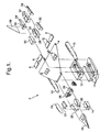
- Fig 1 shows an exploded modular breakdown view of an aircraft in accordance with the invention.
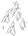
- Fig 2 shows an exploded modular breakdown view of two aircraft wings in accordance with the invention.
- FIG 1 an aircraft 2 is shown broken down into its constituent modular elements.
- the modular wing 4 which forms the main structure element of the aircraft, is shown having modular control surfaces 6 and structural interface locations 8 for the mounting of the podded modular engine units 10.
- the weapons modules 12 are designed to be assembled to the underside of the wing module 4 thereby forming the centre section structure of said wing 4.
- the nose undercarriage unit 14 is designed to be located between the nose cone module 18, and cockpit surround structure 20, the environmental control system module 22 and ultimately the cockpit canopy 24.
- the avionics systems modules are contained within unit 26 shown forming the interface between the forward end of the structural centre section of the wing 4 and the rear of the cockpit area structure 20.
- Aft of the wing module 4 the rear undercarriage module 28 is shown bounded by the hydraulics module 16 and two rear fuselage structural members 30.
- Aft of the hydraulics module 16 is shown a rear weapons module 32 bounded by two tail section structural members 34 and the tail fin unit 38. Additionally, the starboard tail structural member 34 is shown containing the auxilliary power unit module 36.
- Fig 2 shows the break down of the modular construction of two wing units for an aircraft in accordance with the invention, namely, a small wing area platform 40 and a larger wing area platform 42.
- Both the small and the large wing area platform modules have a number of common elements, namely, modular control surfaces 44 the rear structural element of the wing 46 and associated leading edges 48.
- a forward structural section 50 and associated leading edges 52 are used, whereas for the production of a large wing area platform the extended forward structual section 54 and associated leading edge units 56 are utilised.
- engine modules 10 can be designed to accommodate a wide range of engine types, but the interface connections to the wing module 4 will be maintained thereby allowing the rapid assembly and/or disassembly of the engine.
- the design of aircraft variants is made an immeasurably simpler task.
- the common features of the smaller wing aircraft i.e. 44, 46, 48
- the common features of the smaller wing aircraft can be utilised in combination with a larger forward structural area for the wing 54, 56 thereby producing a larger wing lift area, an increased wingborne fuel capacity, a resulting longer fuselage and an increased size aperture for the attachment of a range of weapons modules 12.
- design permutations are numerous when using such a design approach thereby providing a comprehensive collection of aircraft types each being specifically tailored to meet particular mission criteria.
- design and manufacturing methods can just as easily be applied to civil aircraft construction, thereby offering increased flexibility across a range of passenger and transport aircraft.
Landscapes
- Engineering & Computer Science (AREA)
- Aviation & Aerospace Engineering (AREA)
- Manufacturing & Machinery (AREA)
- Mechanical Engineering (AREA)
- Transportation (AREA)
- Automatic Assembly (AREA)
- Casting Or Compression Moulding Of Plastics Or The Like (AREA)
- Moulding By Coating Moulds (AREA)
- Injection Moulding Of Plastics Or The Like (AREA)
Abstract
Description
- This invention relates to the field of aircraft manufacture, and more specifically to the field of modular manufacture of aircraft which can be readily modified and adapted to meet any one of a variety of flight requirements.
- Traditional design techniques and trends within the aircraft industry have led designers to produce aircraft with profiles which use double curvature panels to describe their external lines. The use of such complicated external shapes in the design of both military and civil aircraft has resulted in the need for elaborate and therefore expensive tooling used in both the manufacture of detailed parts and final assembly.
- Within the military aircraft industry, traditional design drivers have been for operational performance improvements, however, more recently a switch in emphasis has been towards providing an effective balance between performance improvement and life cycle cost reductions. This new direction in aircraft design has enabled engineers to study the possibilities of eliminating the familiar double curvature airframes and additionally has provided for research into possible new methods of manufacture and assembly for faceted structures.
- One of the prime cost driving elements associated with the final assembly of modern combat aircraft is that relating to the installation of aircraft systems. The integration and final assembly of environmental control systems (ECS), engine systems, fuel systems, life support systems and avionics is arguably the most time consuming and expensive area of final assembly and therefore much research has been conducted into the possible reduction in complexity of such systems in combination with the introduction of faceted fuselage outer profiles.
- Conventional methods of aircraft manufacture have required a vast range of specialised machining processes to cope with the assembly of double curvature structure and panelling along with the requirements for engineering practises such as shimming or adjustment, contour cutting, drilling and adjustment of details during the assembly phase of aircraft production. A further product of double curvature fuselage designs is the requirement for handed components, and in most cases the use of a wide range of fasteners to cater for the interface requirements of such complex shaped designs.
- Our invention provides a method of manufacture for aircraft which substantially reduces the need for high manpower requirements on aircraft final assembly by the simplification of both the manufacturing and integration processes related to both structure and aircraft systems.
- According to the present invention a method of manufacture of an aircraft is characterised in that it comprises the manufacture of a range of interconnectable demountable structural modules, selecting a pre-determined set of said structural modules defining one of a plurality of aircraft variants, and assembling the selected set of modules to form the required aircraft variant.
- The structural modules manufactures may include interchangeable common modules for providing identical aircraft facilities as required at one or more positions on the aircraft. For example the common modules may comprise modular control surfaces to provide aerodynamic control forces when assembled on the aircraft at a selected one of a plurality of wing or tail positions. In another example the common modules may comprise modular leading edges for providing reduced drag airflow when assembled on the aircraft at a selected one of wing or tail leading edge locations.
- The structural modules manufactured may include interchangeable systems modules for providing selected system functions to the aircraft each taking the form of a modular structure housing the selected system equipment. For example the system modules may comprise modular environmental control systems for providing the assembled aircraft with an environmental control system at a chosen location on the aircraft.
- The structural modules manufactured preferably have structure substantially formed from planar panels. The panels may be joined together to provide a faceted external shape and the modules when assembled on the aircraft may then give the aircraft an overall planar, faceted surface having stealth characteristics. Such a construction of the modules has other benefits for example ease of manufacture and installation or removal, storage and handling.
- The method of manufacture of aircraft may be characterised in that it further includes the steps of manufacturing aircraft wing modules comprising at least:
- manufacturing a rear structural wing element and an associated plurality of interchangeable, demountable, modular control surfaces,
- manufacturing at least two forward structural wing elements each designed to meet a flight requirement different to the flight requirements of the other forward structural wing element or elements and an associated plurality of pairs of interchangeable, demountable, modular leading edges, and
- selecting one of said at least two forward structural wing elements and attaching it to said rear structural wing element.
-
- A specific embodiment of the invention will now be described by way of example only with reference to the following drawings:-
- Fig 1 shows an exploded modular breakdown view of an aircraft in accordance with the invention.
- Fig 2 shows an exploded modular breakdown view of two aircraft wings in accordance with the invention.
- In Fig 1, an
aircraft 2 is shown broken down into its constituent modular elements. The modular wing 4, which forms the main structure element of the aircraft, is shown havingmodular control surfaces 6 andstructural interface locations 8 for the mounting of the poddedmodular engine units 10. Additionally, theweapons modules 12 are designed to be assembled to the underside of the wing module 4 thereby forming the centre section structure of said wing 4. Thenose undercarriage unit 14 is designed to be located between thenose cone module 18, andcockpit surround structure 20, the environmentalcontrol system module 22 and ultimately thecockpit canopy 24. The avionics systems modules are contained withinunit 26 shown forming the interface between the forward end of the structural centre section of the wing 4 and the rear of thecockpit area structure 20. - Aft of the wing module 4 the
rear undercarriage module 28 is shown bounded by thehydraulics module 16 and two rear fuselagestructural members 30. Aft of thehydraulics module 16 is shown arear weapons module 32 bounded by two tail sectionstructural members 34 and thetail fin unit 38. Additionally, the starboard tailstructural member 34 is shown containing the auxilliarypower unit module 36. - Fig 2 shows the break down of the modular construction of two wing units for an aircraft in accordance with the invention, namely, a small
wing area platform 40 and a largerwing area platform 42. Both the small and the large wing area platform modules have a number of common elements, namely,modular control surfaces 44 the rear structural element of thewing 46 and associated leadingedges 48. - For the assembly of a small wing area platform 40 a forward
structural section 50 and associated leadingedges 52 are used, whereas for the production of a large wing area platform the extended forwardstructual section 54 and associated leadingedge units 56 are utilised. - Using the modular aircraft design approach engineers are able to select common modular functions, such as for
example hydraulics module 16 and the environmentalcontrol system module 22 such that they can be used on a wide range of aircraft without being limited to the specific detailed design required for the installation of such modules in conventional double curvature fuselages. Additionallyengine modules 10 can be designed to accommodate a wide range of engine types, but the interface connections to the wing module 4 will be maintained thereby allowing the rapid assembly and/or disassembly of the engine. - When an aircraft designer is considering differing roles for an aircraft type, then using the modular structure and modular systems approach, the design of aircraft variants is made an immeasurably simpler task. For example, if an aircraft type for operational reasons requires either a longer range and/or an increased take off weight or weapons load, then using the modular design approach the common features of the smaller wing aircraft (i.e. 44, 46, 48) can be utilised in combination with a larger forward structural area for the
wing weapons modules 12. - Applying the principle of interchangeability to modular aircraft design not only reduces the time required for assembly of aircraft but also provides for the repair and maintenance of such aircraft built in accordance with the invention to be greatly simplified. For example should there by an environmental control system failure or problem, by housing all of the essential features of the environmental control in
module 16 should it be required, then that individual module can be disconnected from the aircraft and replaced in situ thereby avoiding the problems associated with conventional combat aircraft whereby the removal of major environmental control components would require the disassembly of areas of structure and the removal of individual components. - It can be seen that the design permutations are numerous when using such a design approach thereby providing a comprehensive collection of aircraft types each being specifically tailored to meet particular mission criteria. Such design and manufacturing methods can just as easily be applied to civil aircraft construction, thereby offering increased flexibility across a range of passenger and transport aircraft.
Claims (11)
- A method of manufacture of an aircraft characterised in that it comprises the manufacture of a range of interconnectable, demountable, structural modules (4, 6, 10, 12, 14, 16, 18, 20, 22, 26, 28, 30, 32, 34, 36, 38), selecting a pre-determined set of said structural modules defining one of a plurality of aircraft variants, and assembling the selected set of modules to form the required aircraft variant.
- A method of manufacture of an aircraft as claimed in claim 1 characterised in that the structural modules (4, 6, 10.....) manufactured may include interchangeable common module means (44, 48) for providing identical aircraft facilities as required at one or more positions on the aircraft.
- A method of manufacture of an aircraft as claimed in claim 2 characterised in that the common modules (4, 6, 10.....) comprise modular control surfaces (6, 44) for providing aerodynamic control forces at a selected one of a plurality of wing or tail positions.
- A method of manufacture of an aircraft as claimed in claim 2 characterised in that the common modules (4, 6, 10....) comprise modular leading edges (48, 52, 56) for providing reduced drag airflow at a selected one of wing or tail leading edge locations.
- A method of manufacture of an aircraft as claimed in any of the preceding claims characterised in that the structural modules (4, 6, 10....) manufactured may include interchangeable systems modules (16, 22, 26, ) for providing selected system functions to the aircraft comprising modular structure housing the selected system equipment.
- A method of manufacture of an aircraft as claimed in claim 5 characterised in that the system modules comprise a modular environmental control system (22) for providing the aircraft with an environmental control system at a chosen location on the aircraft (2).
- A method of manufacture of an aircraft as claimed in any preceding claim characterised in that the structural modules (4, 6, 10....) manufactured have structure substantially formed from planar panels.
- A method of manufacture of an aircraft as claimed in claim 7 characterised in that the panels are joined together to provide a faceted external shape and the modules (4, 6, 10....) when assembled on the aircraft (2) give the aircraft (2) an overall planar faceted surface.
- A method of manufacture of an aircraft as claimed in any preceding claim characterised in that it includes the steps of:manufacturing a rear structural wing element (46) and an associated plurality of interchangeable, demountable, modular control surfaces (44, 48);manufacturing at least two forward structural wing elements (50, 54) each designed to meet a flight requirement different from the flight requirement of the other forward structural wing element or elements (50, 54) and an associated plurality of pairs of interchangeable, demountable, modular leading edges (52, 56), and;selecting one of said at least two forward structural wing elements (50, 54) and attaching it to said rear structural wing element (40, 42).
- A method of manufacture of an aircraft as claimed in claim 9 characterised in that the structural modules (44, 48, 52, 56) have structure substantially formed from planar panels.
- A method of manufacture of an aircraft as claimed in claim 10 characterised in that the panels are joined together to provide a faceted external shape and the modules (44, 48, 52, 56) when assembled on the aircraft give the wings (40, 42) of the aircraft (2) an overall planar faceted surface.
Applications Claiming Priority (2)
| Application Number | Priority Date | Filing Date | Title |
|---|---|---|---|
| GB9718656A GB2328918A (en) | 1997-09-04 | 1997-09-04 | Selecting modules to produce aircraft variants |
| GB9718656 | 1997-09-04 |
Publications (2)
| Publication Number | Publication Date |
|---|---|
| EP0900726A1 true EP0900726A1 (en) | 1999-03-10 |
| EP0900726B1 EP0900726B1 (en) | 2002-04-17 |
Family
ID=10818451
Family Applications (1)
| Application Number | Title | Priority Date | Filing Date |
|---|---|---|---|
| EP98307078A Expired - Lifetime EP0900726B1 (en) | 1997-09-04 | 1998-09-03 | Manufacture of aircraft |
Country Status (5)
| Country | Link |
|---|---|
| US (1) | US6065720A (en) |
| EP (1) | EP0900726B1 (en) |
| AT (1) | ATE216330T1 (en) |
| DE (1) | DE69804913T2 (en) |
| GB (1) | GB2328918A (en) |
Cited By (8)
| Publication number | Priority date | Publication date | Assignee | Title |
|---|---|---|---|---|
| CN101829900A (en) * | 2010-03-30 | 2010-09-15 | 浙江大学 | Layout method of grand cross butting locator of aircraft wing body |
| EP1752376A3 (en) * | 2005-08-13 | 2010-10-13 | LFK-Lenkflugkörpersysteme GmbH | Aircraft, in particular unmanned aircraft, with at least one weapons bay |
| EP2502828A1 (en) | 2011-03-25 | 2012-09-26 | Eurocopter | Aerodynamic surface and aircraft |
| US8479394B2 (en) | 2005-09-22 | 2013-07-09 | Airbus Operations Limited | Assembly of aircraft components |
| FR3000017A1 (en) * | 2012-12-21 | 2014-06-27 | Airbus Operations Sas | FRONT AIRCRAFT TIP WITH INTEGRATED COCKPIT MODULES AND AIRCRAFT SLEEVE |
| FR3048226A1 (en) * | 2016-02-26 | 2017-09-01 | Airbus Operations Sas | AIRCRAFT WITH MODULAR REAR STRUCTURE. |
| EP3296193A1 (en) * | 2016-09-20 | 2018-03-21 | Bell Helicopter Textron Inc. | Modular payload systems for aircraft |
| EP3333072A1 (en) * | 2016-12-07 | 2018-06-13 | AIRBUS HELICOPTERS DEUTSCHLAND GmbH | An aircraft with an airframe that comprises a load carrying framework |
Families Citing this family (22)
| Publication number | Priority date | Publication date | Assignee | Title |
|---|---|---|---|---|
| RU2297371C2 (en) * | 2001-01-19 | 2007-04-20 | Те Боинг Компани | Integral and/or modular high-speed aircraft |
| US6568632B2 (en) * | 2001-04-04 | 2003-05-27 | The Boeing Company | Variable size blended wing body aircraft |
| US7644888B2 (en) * | 2002-05-15 | 2010-01-12 | The Boeing Company | High-speed aircraft and methods for their manufacture |
| US6926235B2 (en) * | 2003-06-20 | 2005-08-09 | The Boeing Company | Runway-independent omni-role modularity enhancement (ROME) vehicle |
| US7234667B1 (en) * | 2003-12-11 | 2007-06-26 | Talmage Jr Robert N | Modular aerospace plane |
| US7093798B2 (en) * | 2004-01-30 | 2006-08-22 | The Boeing Company | Transformable airplane |
| RU2323850C2 (en) * | 2005-06-15 | 2008-05-10 | ООО "Центральный научно-исследовательский институт авиационных ракетных комплексов и систем" | Multivariant unpiloted flying object |
| RU2408501C2 (en) * | 2008-09-16 | 2011-01-10 | Владимир Александрович Самсонов | Aircraft |
| RU2389653C1 (en) * | 2009-04-10 | 2010-05-20 | Эдуард Дмитриевич Житников | Nacelle with inner wing |
| DE102009023391A1 (en) * | 2009-05-29 | 2010-12-02 | Airbus Deutschland Gmbh | Method and system for assembling interior components in an aircraft |
| JP2012533476A (en) * | 2009-07-22 | 2012-12-27 | エアロヴァイロンメント インコーポレイテッド | Reconfigurable aircraft |
| ES2378794B1 (en) * | 2009-09-18 | 2013-01-29 | Airbus Operations, S.L. | PROCEDURE OF DESIGN AND MANUFACTURE OF PARTS OF VARIABLE CONFIGURATION MODELS. |
| US10118686B2 (en) * | 2012-09-27 | 2018-11-06 | The Boeing Company | Wing root insert system for an aircraft family |
| FR3000024B1 (en) * | 2012-12-21 | 2015-01-02 | Airbus Operations Sas | AIRCRAFT COCKPIT WITH FLOOR FLOOR |
| US11364448B2 (en) * | 2014-10-20 | 2022-06-21 | Huntar Company | Mix and match toy kit |
| US9505484B1 (en) | 2016-04-11 | 2016-11-29 | Nasser M. Al-Sabah | Modular aircraft system |
| US10640215B2 (en) | 2016-09-20 | 2020-05-05 | Textron Innovations Inc. | Modular refueling systems for aircraft |
| US11738851B2 (en) * | 2021-09-17 | 2023-08-29 | Blended Wing Aircraft, Inc. | Systems and methods for modular aircraft |
| GB2634659A (en) * | 2022-05-13 | 2025-04-16 | Firestorm Labs Inc | Mission-adaptable aerial vehicle and methods for in-field assembly and use |
| WO2023236963A1 (en) * | 2022-06-09 | 2023-12-14 | 影石创新科技股份有限公司 | Unmanned aerial vehicle |
| US12246830B1 (en) * | 2023-09-08 | 2025-03-11 | Jetzero, Inc. | Modular blended wing body (BWB) aircraft and method of manufacture |
| WO2025193944A1 (en) | 2024-03-13 | 2025-09-18 | Firestorm Labs, Inc. | Additive manufactured integral fastening system for mission adaptable unmanned aerial vehicles |
Citations (5)
| Publication number | Priority date | Publication date | Assignee | Title |
|---|---|---|---|---|
| US3640491A (en) * | 1970-04-15 | 1972-02-08 | Robert R Harrison | Airplane construction frame |
| US4736910A (en) * | 1984-08-10 | 1988-04-12 | Flight Concepts Limited Partnership | Aircraft with interchangeable fuselage |
| DE4131569A1 (en) * | 1991-09-23 | 1993-03-25 | Josef Dr Fleischer | Variable modular construction aircraft - has coded subsections mass produced and assembled on site into required model |
| DE4218197A1 (en) * | 1992-06-03 | 1993-12-09 | Deutsche Aerospace | Multipurpose aircraft for different mission tasks - has selected rear part containing appropriate specific task devices connected to front part containing aircraft drive controls |
| WO1997022516A1 (en) * | 1995-12-15 | 1997-06-26 | The Boeing Company | Multi-service common airframe-based aircraft |
Family Cites Families (11)
| Publication number | Priority date | Publication date | Assignee | Title |
|---|---|---|---|---|
| GB398069A (en) * | 1932-12-13 | 1933-09-07 | Joseph Albessard | Aeroplanes with autostable arrangements of planes |
| GB515562A (en) * | 1938-07-01 | 1939-12-07 | Fairey Aviat Co Ltd | Improvements in or relating to the structure of aircraft |
| GB528911A (en) * | 1939-05-06 | 1940-11-11 | Fairey Aviat Co Ltd | Improvements in or relating to the construction of aircraft |
| GB755288A (en) * | 1953-06-30 | 1956-08-22 | Morane Saulnier | Aircraft with a wing of generally triangular form |
| GB873679A (en) * | 1958-10-08 | 1961-07-26 | English Electric Co Ltd | Improvements in and relating to aircraft |
| AT235150B (en) * | 1963-04-11 | 1964-08-10 | Hirtenberger Patronen | Missiles composed of a large number of aerodynamically shaped, similar basic elements |
| US4379533A (en) * | 1979-07-02 | 1983-04-12 | Lockheed Corporation | Transport airplane |
| US4449679A (en) * | 1982-03-05 | 1984-05-22 | Fairchild Industries, Inc. | Multi role aircraft |
| US4417708A (en) * | 1982-05-12 | 1983-11-29 | Grumman Aerospace Corporation | Interchangeable wing aircraft |
| AU5207386A (en) * | 1984-11-23 | 1986-06-18 | Fox Brothers Limited Partnership | Graduated aircraft design and construction method |
| EP0247063A4 (en) * | 1985-11-22 | 1989-02-22 | Fox Brothers Ltd | Graduated aircraft design and construction method. |
-
1997
- 1997-09-04 GB GB9718656A patent/GB2328918A/en not_active Withdrawn
-
1998
- 1998-08-31 US US09/144,263 patent/US6065720A/en not_active Expired - Fee Related
- 1998-09-03 EP EP98307078A patent/EP0900726B1/en not_active Expired - Lifetime
- 1998-09-03 AT AT98307078T patent/ATE216330T1/en not_active IP Right Cessation
- 1998-09-03 DE DE69804913T patent/DE69804913T2/en not_active Expired - Fee Related
Patent Citations (5)
| Publication number | Priority date | Publication date | Assignee | Title |
|---|---|---|---|---|
| US3640491A (en) * | 1970-04-15 | 1972-02-08 | Robert R Harrison | Airplane construction frame |
| US4736910A (en) * | 1984-08-10 | 1988-04-12 | Flight Concepts Limited Partnership | Aircraft with interchangeable fuselage |
| DE4131569A1 (en) * | 1991-09-23 | 1993-03-25 | Josef Dr Fleischer | Variable modular construction aircraft - has coded subsections mass produced and assembled on site into required model |
| DE4218197A1 (en) * | 1992-06-03 | 1993-12-09 | Deutsche Aerospace | Multipurpose aircraft for different mission tasks - has selected rear part containing appropriate specific task devices connected to front part containing aircraft drive controls |
| WO1997022516A1 (en) * | 1995-12-15 | 1997-06-26 | The Boeing Company | Multi-service common airframe-based aircraft |
Cited By (10)
| Publication number | Priority date | Publication date | Assignee | Title |
|---|---|---|---|---|
| EP1752376A3 (en) * | 2005-08-13 | 2010-10-13 | LFK-Lenkflugkörpersysteme GmbH | Aircraft, in particular unmanned aircraft, with at least one weapons bay |
| US8479394B2 (en) | 2005-09-22 | 2013-07-09 | Airbus Operations Limited | Assembly of aircraft components |
| CN101829900A (en) * | 2010-03-30 | 2010-09-15 | 浙江大学 | Layout method of grand cross butting locator of aircraft wing body |
| CN101829900B (en) * | 2010-03-30 | 2012-11-28 | 浙江大学 | Layout method of grand cross butting locator of aircraft wing body |
| EP2502828A1 (en) | 2011-03-25 | 2012-09-26 | Eurocopter | Aerodynamic surface and aircraft |
| FR3000017A1 (en) * | 2012-12-21 | 2014-06-27 | Airbus Operations Sas | FRONT AIRCRAFT TIP WITH INTEGRATED COCKPIT MODULES AND AIRCRAFT SLEEVE |
| US9290259B2 (en) | 2012-12-21 | 2016-03-22 | Airbus Operations (Sas) | Aircraft nose with cockpit and avionics bay modules integrated therein |
| FR3048226A1 (en) * | 2016-02-26 | 2017-09-01 | Airbus Operations Sas | AIRCRAFT WITH MODULAR REAR STRUCTURE. |
| EP3296193A1 (en) * | 2016-09-20 | 2018-03-21 | Bell Helicopter Textron Inc. | Modular payload systems for aircraft |
| EP3333072A1 (en) * | 2016-12-07 | 2018-06-13 | AIRBUS HELICOPTERS DEUTSCHLAND GmbH | An aircraft with an airframe that comprises a load carrying framework |
Also Published As
| Publication number | Publication date |
|---|---|
| DE69804913T2 (en) | 2003-01-16 |
| US6065720A (en) | 2000-05-23 |
| GB9718656D0 (en) | 1997-11-05 |
| EP0900726B1 (en) | 2002-04-17 |
| DE69804913D1 (en) | 2002-05-23 |
| GB2328918A (en) | 1999-03-10 |
| ATE216330T1 (en) | 2002-05-15 |
Similar Documents
| Publication | Publication Date | Title |
|---|---|---|
| EP0900726B1 (en) | Manufacture of aircraft | |
| US9493226B2 (en) | Multi-role aircraft with interchangeable mission modules | |
| US7234667B1 (en) | Modular aerospace plane | |
| US9688382B2 (en) | Method of constructing a fixed-wing aircraft | |
| US6726149B2 (en) | Derivative aircraft and methods for their manufacture | |
| EP3501994A1 (en) | Aircraft and method for producing an aircraft | |
| US10899463B2 (en) | Segmented pylon for an aircraft propulsion system | |
| US8100362B2 (en) | Cockpit and aircraft including such cockpit | |
| CN208715479U (en) | Modular Supersonic Drone | |
| US20040094664A1 (en) | Apparatuses and methods for attaching engine nacelles to aircraft | |
| CN108820204A (en) | Modularization supersonic speed unmanned plane | |
| US6405977B1 (en) | Modular air intake duct for aircraft | |
| CN115783231A (en) | Modular wing combined aircraft | |
| US9950833B2 (en) | Flexible configuration system, methods, equipment, and aircraft | |
| EP1053174B1 (en) | Dual function structures | |
| CN102123913B (en) | light utility aircraft | |
| EP1038771A1 (en) | Modular vehicle air intake duct | |
| US12466538B1 (en) | Airfoil coupling systems and methods | |
| US12291330B2 (en) | Aircraft wing having a truss system for coupling a center wing section to an outboard wing section | |
| JP2025169631A (en) | manufacturing equipment | |
| CN116729634A (en) | Multi-section separable combined composite material aviation nacelle | |
| EP1471000A2 (en) | Aircraft | |
| VG10 | Introduction to the Super VC10 | |
| HOWISON et al. | Electronic/electric technology benefits study(avionics)[Report, Aug. 1980- Jan. 1982] | |
| HK1072755B (en) | Aircraft |
Legal Events
| Date | Code | Title | Description |
|---|---|---|---|
| PUAI | Public reference made under article 153(3) epc to a published international application that has entered the european phase |
Free format text: ORIGINAL CODE: 0009012 |
|
| AK | Designated contracting states |
Kind code of ref document: A1 Designated state(s): AT BE CH DE DK ES FI FR GB IT LI NL SE |
|
| AX | Request for extension of the european patent |
Free format text: AL;LT;LV;MK;RO;SI |
|
| 17P | Request for examination filed |
Effective date: 19990409 |
|
| AKX | Designation fees paid |
Free format text: AT BE CH CY LI |
|
| RBV | Designated contracting states (corrected) |
Designated state(s): AT BE CH DE DK ES FI FR GB IT LI NL SE |
|
| REG | Reference to a national code |
Ref country code: DE Ref legal event code: 8566 |
|
| 17Q | First examination report despatched |
Effective date: 20000717 |
|
| RAP1 | Party data changed (applicant data changed or rights of an application transferred) |
Owner name: BAE SYSTEMS PLC |
|
| GRAG | Despatch of communication of intention to grant |
Free format text: ORIGINAL CODE: EPIDOS AGRA |
|
| GRAG | Despatch of communication of intention to grant |
Free format text: ORIGINAL CODE: EPIDOS AGRA |
|
| GRAH | Despatch of communication of intention to grant a patent |
Free format text: ORIGINAL CODE: EPIDOS IGRA |
|
| GRAH | Despatch of communication of intention to grant a patent |
Free format text: ORIGINAL CODE: EPIDOS IGRA |
|
| REG | Reference to a national code |
Ref country code: GB Ref legal event code: IF02 |
|
| REG | Reference to a national code |
Ref country code: DE Ref legal event code: 8570 |
|
| GRAA | (expected) grant |
Free format text: ORIGINAL CODE: 0009210 |
|
| AK | Designated contracting states |
Kind code of ref document: B1 Designated state(s): AT BE CH DE DK ES FI FR GB IT LI NL SE |
|
| PG25 | Lapsed in a contracting state [announced via postgrant information from national office to epo] |
Ref country code: NL Free format text: LAPSE BECAUSE OF FAILURE TO SUBMIT A TRANSLATION OF THE DESCRIPTION OR TO PAY THE FEE WITHIN THE PRESCRIBED TIME-LIMIT Effective date: 20020417 Ref country code: LI Free format text: LAPSE BECAUSE OF FAILURE TO SUBMIT A TRANSLATION OF THE DESCRIPTION OR TO PAY THE FEE WITHIN THE PRESCRIBED TIME-LIMIT Effective date: 20020417 Ref country code: IT Free format text: LAPSE BECAUSE OF FAILURE TO SUBMIT A TRANSLATION OF THE DESCRIPTION OR TO PAY THE FEE WITHIN THE PRESCRIBED TIME-LIMIT;WARNING: LAPSES OF ITALIAN PATENTS WITH EFFECTIVE DATE BEFORE 2007 MAY HAVE OCCURRED AT ANY TIME BEFORE 2007. THE CORRECT EFFECTIVE DATE MAY BE DIFFERENT FROM THE ONE RECORDED. Effective date: 20020417 Ref country code: FI Free format text: LAPSE BECAUSE OF FAILURE TO SUBMIT A TRANSLATION OF THE DESCRIPTION OR TO PAY THE FEE WITHIN THE PRESCRIBED TIME-LIMIT Effective date: 20020417 Ref country code: CH Free format text: LAPSE BECAUSE OF FAILURE TO SUBMIT A TRANSLATION OF THE DESCRIPTION OR TO PAY THE FEE WITHIN THE PRESCRIBED TIME-LIMIT Effective date: 20020417 Ref country code: BE Free format text: LAPSE BECAUSE OF FAILURE TO SUBMIT A TRANSLATION OF THE DESCRIPTION OR TO PAY THE FEE WITHIN THE PRESCRIBED TIME-LIMIT Effective date: 20020417 Ref country code: AT Free format text: LAPSE BECAUSE OF FAILURE TO SUBMIT A TRANSLATION OF THE DESCRIPTION OR TO PAY THE FEE WITHIN THE PRESCRIBED TIME-LIMIT Effective date: 20020417 |
|
| REF | Corresponds to: |
Ref document number: 216330 Country of ref document: AT Date of ref document: 20020515 Kind code of ref document: T |
|
| REG | Reference to a national code |
Ref country code: CH Ref legal event code: EP |
|
| REF | Corresponds to: |
Ref document number: 69804913 Country of ref document: DE Date of ref document: 20020523 |
|
| PG25 | Lapsed in a contracting state [announced via postgrant information from national office to epo] |
Ref country code: SE Free format text: LAPSE BECAUSE OF FAILURE TO SUBMIT A TRANSLATION OF THE DESCRIPTION OR TO PAY THE FEE WITHIN THE PRESCRIBED TIME-LIMIT Effective date: 20020717 Ref country code: DK Free format text: LAPSE BECAUSE OF FAILURE TO SUBMIT A TRANSLATION OF THE DESCRIPTION OR TO PAY THE FEE WITHIN THE PRESCRIBED TIME-LIMIT Effective date: 20020717 |
|
| ET | Fr: translation filed | ||
| NLV1 | Nl: lapsed or annulled due to failure to fulfill the requirements of art. 29p and 29m of the patents act | ||
| ET | Fr: translation filed | ||
| PG25 | Lapsed in a contracting state [announced via postgrant information from national office to epo] |
Ref country code: ES Free format text: LAPSE BECAUSE OF FAILURE TO SUBMIT A TRANSLATION OF THE DESCRIPTION OR TO PAY THE FEE WITHIN THE PRESCRIBED TIME-LIMIT Effective date: 20021030 |
|
| REG | Reference to a national code |
Ref country code: CH Ref legal event code: PL |
|
| PLBE | No opposition filed within time limit |
Free format text: ORIGINAL CODE: 0009261 |
|
| STAA | Information on the status of an ep patent application or granted ep patent |
Free format text: STATUS: NO OPPOSITION FILED WITHIN TIME LIMIT |
|
| 26N | No opposition filed |
Effective date: 20030120 |
|
| PGFP | Annual fee paid to national office [announced via postgrant information from national office to epo] |
Ref country code: FR Payment date: 20080811 Year of fee payment: 11 |
|
| PGFP | Annual fee paid to national office [announced via postgrant information from national office to epo] |
Ref country code: GB Payment date: 20080822 Year of fee payment: 11 |
|
| PGFP | Annual fee paid to national office [announced via postgrant information from national office to epo] |
Ref country code: DE Payment date: 20080829 Year of fee payment: 11 |
|
| GBPC | Gb: european patent ceased through non-payment of renewal fee |
Effective date: 20090903 |
|
| REG | Reference to a national code |
Ref country code: FR Ref legal event code: ST Effective date: 20100531 |
|
| PG25 | Lapsed in a contracting state [announced via postgrant information from national office to epo] |
Ref country code: FR Free format text: LAPSE BECAUSE OF NON-PAYMENT OF DUE FEES Effective date: 20090930 Ref country code: DE Free format text: LAPSE BECAUSE OF NON-PAYMENT OF DUE FEES Effective date: 20100401 |
|
| PG25 | Lapsed in a contracting state [announced via postgrant information from national office to epo] |
Ref country code: GB Free format text: LAPSE BECAUSE OF NON-PAYMENT OF DUE FEES Effective date: 20090903 |