EP0900616A2 - Saw blade with saw teeth configuration and method for its production - Google Patents
Saw blade with saw teeth configuration and method for its production Download PDFInfo
- Publication number
- EP0900616A2 EP0900616A2 EP98116700A EP98116700A EP0900616A2 EP 0900616 A2 EP0900616 A2 EP 0900616A2 EP 98116700 A EP98116700 A EP 98116700A EP 98116700 A EP98116700 A EP 98116700A EP 0900616 A2 EP0900616 A2 EP 0900616A2
- Authority
- EP
- European Patent Office
- Prior art keywords
- teeth
- tooth
- height
- follower
- guide
- Prior art date
- Legal status (The legal status is an assumption and is not a legal conclusion. Google has not performed a legal analysis and makes no representation as to the accuracy of the status listed.)
- Granted
Links
Images


Classifications
-
- B—PERFORMING OPERATIONS; TRANSPORTING
- B23—MACHINE TOOLS; METAL-WORKING NOT OTHERWISE PROVIDED FOR
- B23D—PLANING; SLOTTING; SHEARING; BROACHING; SAWING; FILING; SCRAPING; LIKE OPERATIONS FOR WORKING METAL BY REMOVING MATERIAL, NOT OTHERWISE PROVIDED FOR
- B23D61/00—Tools for sawing machines or sawing devices; Clamping devices for these tools
- B23D61/02—Circular saw blades
- B23D61/021—Types of set; Variable teeth, e.g. variable in height or gullet depth: Varying pitch; Details of gullet
-
- Y—GENERAL TAGGING OF NEW TECHNOLOGICAL DEVELOPMENTS; GENERAL TAGGING OF CROSS-SECTIONAL TECHNOLOGIES SPANNING OVER SEVERAL SECTIONS OF THE IPC; TECHNICAL SUBJECTS COVERED BY FORMER USPC CROSS-REFERENCE ART COLLECTIONS [XRACs] AND DIGESTS
- Y10—TECHNICAL SUBJECTS COVERED BY FORMER USPC
- Y10T—TECHNICAL SUBJECTS COVERED BY FORMER US CLASSIFICATION
- Y10T408/00—Cutting by use of rotating axially moving tool
- Y10T408/89—Tool or Tool with support
- Y10T408/895—Having axial, core-receiving central portion
- Y10T408/8957—Having axial, core-receiving central portion and having stepped cutting edges
-
- Y—GENERAL TAGGING OF NEW TECHNOLOGICAL DEVELOPMENTS; GENERAL TAGGING OF CROSS-SECTIONAL TECHNOLOGIES SPANNING OVER SEVERAL SECTIONS OF THE IPC; TECHNICAL SUBJECTS COVERED BY FORMER USPC CROSS-REFERENCE ART COLLECTIONS [XRACs] AND DIGESTS
- Y10—TECHNICAL SUBJECTS COVERED BY FORMER USPC
- Y10T—TECHNICAL SUBJECTS COVERED BY FORMER US CLASSIFICATION
- Y10T83/00—Cutting
- Y10T83/929—Tool or tool with support
- Y10T83/9319—Toothed blade or tooth therefor
- Y10T83/935—Plural tooth groups
- Y10T83/9355—Including intermediate raker tooth
-
- Y—GENERAL TAGGING OF NEW TECHNOLOGICAL DEVELOPMENTS; GENERAL TAGGING OF CROSS-SECTIONAL TECHNOLOGIES SPANNING OVER SEVERAL SECTIONS OF THE IPC; TECHNICAL SUBJECTS COVERED BY FORMER USPC CROSS-REFERENCE ART COLLECTIONS [XRACs] AND DIGESTS
- Y10—TECHNICAL SUBJECTS COVERED BY FORMER USPC
- Y10T—TECHNICAL SUBJECTS COVERED BY FORMER US CLASSIFICATION
- Y10T83/00—Cutting
- Y10T83/929—Tool or tool with support
- Y10T83/9319—Toothed blade or tooth therefor
- Y10T83/9358—Series of dissimilar teeth
Definitions
- the invention relates to a saw blade with one repeating group of teeth coming from an unrestricted chamfered guide tooth with a compared to its width smaller effective ones located in the middle of its tooth tip Cut edge section and a preferably even number set follower teeth, the guide tooth one has a larger tooth height than each of the follower teeth.
- the invention can be used with a band saw blade, i.e. a saw blade with a linear arrangement of the teeth one behind the other, as well a circular saw blade. It is usually only a single guide tooth is provided in the group.
- the Subsequent teeth can be the same, but also different - especially in pairs - have tooth height.
- the invention leaves apply in particular to a bimetal base tape.
- a saw blade is described kind known, which on a base body both unrestricted as well as set teeth, the tips of their teeth consist of a material that is harder than the material of the Basic body is. It can e.g. around tungsten carbide, however also act on high-speed steel.
- the teeth are repetitive Group arranged, the smallest group of one straight guide tooth and two set right and left Subsequent teeth exist.
- the guide tooth has a tooth height that is greater than the common tooth height of the two secondary teeth.
- the guide tooth is phased, so it has in the middle Tooth tip a straight cutting edge section which are arranged in a symmetrical arrangement on the right and left sloping cut edge section connects.
- From DE 36 11 063 A1 is a saw blade at the beginning described type with a group of teeth from one Guide tooth and several secondary teeth known in themselves repetitive cycles are provided.
- the guide tooth has the greatest height and the tooth height decreases in the group, but can also be the same on the following teeth.
- the follow teeth are designed as set teeth and are usually alternating slanted to the left and right provided to this Way to make the width of the cutting channel larger than the width of the body of the saw blade.
- the leading tooth can also be phased.
- the production of different heights Teeth are made by an appropriate milling process or with a tool where the tooth tips are driven by an impact be bent in the direction of the saw band. It closes a grinding process takes place around the cut edges of the teeth to generate the intended height gradation.
- the effective part the length of the ground cutting edges increases in tooth length Tooth in the group, so that the essential cutting work of the leading tooth is to be performed and the two secondary teeth in the essentially only widen the cutting channel, so that a free cut
- From DE 33 00 791 C2 is a saw blade with repetitive Groups of teeth from several consecutive high and several successive low teeth.
- the first group of teeth of equal height contains set and unrestricted Teeth.
- the second group of equally low teeth also contains set and unrestricted teeth.
- Each Group can also have teeth of both heights. Every tooth has first and second, different rake angles and first and second, different clearance angles on. The two different rake and clearance angles can be on each individual tooth through plastic deformation of the tooth tip, in particular by an upsetting process with a pressure stamp are generated at an acute angle to the direction of travel of the saw band is moved.
- the tooth height is also reduced.
- the degree of compression can be adjusted or controlled of the stroke of the pressure stamp can be set or controlled.
- the shape of the teeth can also be cut without milling or grinding. Due to the plastic deformation of a Tooth after tooth a series of teeth can be formed in the between the high teeth of the first group and the low teeth of the second group there is a height difference and the two rake angles and the two relief angles on each Tooth are generated. Also different penetration depths and different divisions can exist within each of the two Groups are realized. It is not recognizable whether the high and low teeth due to the plastic deformation receive different or the same rake angle. Remains on It is not clear whether the height difference that occurs after the plastic deformation the teeth are pre-formed during a previous milling process will or not.
- the invention is based, a comparative task Easy to manufacture saw blade of the type described in the introduction to provide which is advantageously very large rake angle has a reduced vibration behavior and at its use a different chip scale frequency arises.
- this is the case with a saw blade described type achieved in that in any case all follower teeth in the area of their tooth tips one different from each other plastic deformation due to material displacement in Have tape running direction, and that each follower tooth through the different plastic deformation on the one hand increased positive rake angle and on the other hand one has reduced tooth height compared to the guide tooth.
- the invention is based on the idea, at least on the follower teeth primarily due to the different plastic Ultimately deformation of the profiled tooth tips concerned to form different positive rake angles.
- the profiling of the teeth before plastic deformation can be caused in particular by Milling, but also by grinding or punching or by high-energy blasting processes are carried out.
- differences are already understood that occur due to manufacturing tolerances or unavoidable are. For example, already in the manufacture of the Cutter or the profiled grinding wheels larger tolerances be allowed. While striving so far, the tolerances To keep it as small as possible, the invention uses the opposite Path. The same applies to the production and the drive as well as the control of the tool for plastic deformation.
- the pairs of secondary teeth can be at different height levels to each other and to the guide tooth (s) be deformed.
- the different plastic deformation of pairs of follower teeth on different graded levels Height levels will always be in coordination with different ones Cabinet widths made.
- the pair of follow teeth, which on the smallest height level, has the largest cabinet width.
- the pair of follow teeth, which on the greatest height level, has the lowest or smallest cabinet width.
- the pairs of follow teeth that arranged in terms of height also have an intermediate one Cabinet width.
- the saw blade according to the invention has a number of advantages on. Due to the different rake angles due to different plastic deformation while allowing larger tolerances the vibration behavior of the saw blade reduces Sawing in that a different chip scale frequency arises. Extremely large positive rake angles can be achieved not by milling or grinding alone are producible. Due to the plastic deformation of the tooth tips, e.g. can be achieved by upsetting or rolling, the profiled cutting edge gets a greater sharpness. Here the burr formed during milling or grinding in the direction of travel of the saw blade folded. The saw blade according to the invention can finally be produced very easily and inexpensively, in particular in that the follower teeth in one or several groups together or largely simultaneously be plastically deformed. The different plastic deformation can be performed at different levels become.
- These different height levels can be determined by a proportional gradation. For example it makes sense for a group of 7 teeth, the guide tooth, which have a rake angle of about 10 ° after profiling can plastically deform so that he then one Rake angle of about 15 °.
- the guide tooth shows the greatest height at.
- the follower teeth can after the profiling also have a rake angle of 10 °.
- the first couple follower teeth are plastically deformed comparatively more. It gets a rake angle of about 17 °, a height difference -x opposite the guide tooth and a cabinet width (minus Bandwidth) of about a third of the maximum cabinet width of the most deformed pair of follower teeth.
- the second A pair of follower teeth is plastically deformed even more comparatively.
- the third pair of follower teeth is comparatively most plastically deformed. It gets a rake angle of about 21 °, a height difference -3x opposite the guide tooth and the maximum set width.
- the chronological order the teeth in the group are arbitrary. The same applies to other number of teeth in the group.
- the following teeth point to the left and right set teeth, in pairs on the same Height level and are arranged with such limitation that in the projection of all teeth in the band direction in pairs discrete machining areas arise that are not compatible with Machining areas of other teeth overlap.
- the machining areas of the teeth adjoin one another laterally.
- the guide tooth can also be in the area of its tooth tip Different compared to the deformation of the follower teeth have plastic deformation so that it is due to the plastic Deformation on the one hand an enlarged positive rake angle and on the other hand, a comparative compared to the follower teeth has less reduced tooth height.
- the manufacture of the Raw teeth in the group are made by a milling process, whereby in particular, all teeth of a group are milled together
- the raw teeth produced in this way can match, but also have different shapes, particularly with regard to the tooth height and / or one or more positive or neutral rake angle and clearance angle.
- the guide tooth can be a positive one in the area of its tooth tip Rake angle in the range between 5 ° and 25 ° - in particular about 15 ° - and the secondary teeth in the area of their tooth tips positive Rake angle in the range between 5 ° and 30 ° - in particular approximately between 17 ° and 21 °.
- the effective rake angle of the following teeth are usually larger than the effective rake angle of the guide tooth because the follower teeth are usually stronger are plastically deformed than the guide tooth. This can be due to based on the height difference.
- the secondary teeth plastically graded in pairs to different height levels be deformed, with decreasing absolute tooth height with increasing Cabinet width is combined. But it is also possible that Milling raw teeth with different raw chip angles, namely while maintaining the same or different wedge angles between rake angle and clearance angle.
- the saw blade can be between the tooth height of the guide tooth and the tooth height of a follower tooth a height difference in the range of about 0.05 to 0.30 mm - in particular between 0.08 and 0.15 mm - exhibit.
- This difference in height can occur when profiling the raw teeth be fully or partially pre-trained. The final However, the difference in height results from the plastic deformation the tooth tips or after setting the secondary teeth.
- the middle tooth can be found below the tooth height of the set secondary teeth Tooth height or the maximum tooth height, i.e. the tooth height of the inner corner of the set follower tooth can be understood.
- the Height difference should not be chosen too large to the chip cleared from the guide tooth is not too thick do. If follow teeth in pairs on different Height levels or different in different levels plastically deformed, the maximum deformation of the the two smallest secondary teeth the plastic deformability of teeth not exceed.
- the guide tooth can have a phase angle in the range between 30 ° and have 60 °.
- the training and arrangement of the phase can be made so that only about the outer half of each set Follower tooth and / or the inner half of the through the Phase formed cutting edge of the guide tooth works. This applies to the two immediately following a guide tooth Followers in the group.
- phase angle of the guide tooth and the set width of the follower teeth on top of each other be coordinated that the load on the saw blade in about is evenly distributed on the teeth.
- the process of making a saw blade for making a saw blade with a repeating group of teeth that from an unrestrained phased guide tooth with a cut edge section running straight in the middle of its tooth tip and a preferably even number of restricted ones
- the guide tooth being a larger one Tooth height than each of the follower teeth
- first the teeth as raw teeth be profiled so that the tooth tips at least of the follower teeth so different due to material displacement in the direction of belt travel be plastically deformed so that each follower tooth through the different plastic deformation on the one hand increased positive rake angle and on the other hand each has reduced tooth height compared to the guide tooth, and so one guide tooth and several follower teeth are formed in the group and that the guide tooth in the group by grinding be phased and the secondary teeth set.
- the raw strip is made from bimetal profiled in a manner known per se, e.g. milled that the Raw teeth appear.
- the raw strip is profiled in sections, so that several raw teeth emerge simultaneously per section.
- the number of raw teeth can be useful with the number of teeth match in the group. It is particularly easy if all raw teeth with the same shape and tooth height be profiled and only the manufacturing tolerances impact, which are admittedly allowed, yes are even desired. Then there is the different plastic Deformation of the tooth tips of the teeth, being from the raw teeth Guide teeth and follower teeth. You can do that too and should affect manufacturing tolerances that be consciously admitted, even desirable.
- the leading tooth and the follower teeth in the group get relatively large, different positive rake angles and different tooth heights, the tooth heights of the subsequent teeth roughly match or are relatively close to each other, so that the Height difference to the tooth height of the guide tooth results.
- This Design affects the vibration behavior of the saw blade positive in use.
- the follow teeth will restricted, with the setting in pairs. Several too Pairs of follower teeth can be together, i.e. at the same time, limited with the same or different pairs Cabinet width. A possible or necessary heat treatment can join.
- the guide tooth is pro Group phased by grinding.
- All teeth can advantageously be used as raw teeth in particular with regard to the raw tooth height and the raw chip angle more consistent Shape be profiled, then the die Subsequent teeth forming raw teeth in the group compared to Guide tooth are deformed more plastically.
- the teeth it is also possible for the teeth to be used as raw teeth especially with regard to the raw tooth height but also e.g. of Profiled rake angle of different shape and so the Guide tooth and the follower teeth are pre-formed. It will then the tooth tips of the guide tooth thus formed and the Followers in the group are plastically deformed so differently, that the leading tooth and each following tooth in the group by the plastic deformation on the one hand an enlarged positive Rake angle and on the other hand each follower one with respect to that Guide tooth has reduced tooth height.
- the set secondary teeth are, according to their profiling, in particular in pairs, on different levels Height levels sculpted differently, the Steps of decreasing height differences with steps of increasing rake angles and increasing cabinet width differences are combined, namely when the teeth are arranged in any order in the group.
- the height differences from level to level can about 0.05 mm.
- the rake angle differences can be about 2 °.
- At least tooth tips of the guide tooth and the follower teeth a group together, i.e. more or less at the same time, plastically deformed, the deformation strokes to the At least partially overlay raw teeth. Independently of constant or variable divisions can be realized.
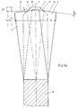
- the 1a and 1b illustrate the basic arrangement and Formation of the teeth on the saw blade. It is a leading tooth 1 and several follower teeth 2, 3, 4, 5, .. are provided. Of the Guide tooth 1 and the follower teeth 2, 3, .. are in one repeating group 6 arranged. Each group 6 represents one Sequence of teeth in which the teeth are directly on top of each other consequences. Groups 6 are also connected to each other.
- the follower teeth 2, 3, .. are each provided in an even number, whereby they are assigned to one another in pairs.
- the leading tooth 1 is always a straight, unrestrained tooth.
- the follow teeth 2, 3, 4, 5, .. are always set teeth, being the set in the tooth sequence alternately to the right and left or vice versa is carried out.
- the guide tooth 1 always has one greater tooth height than the secondary teeth 2, 3, ...
- Group 6 has a guide tooth 1 and two follower teeth 2 and 3.
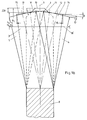
- Fig. 1b and 6 illustrate a group 6, which consists of a guide tooth 1 and four secondary teeth 2, 3, 4 and 5.
- the only single guide tooth 1 in a group 6 is a straight tooth, the tooth width of which corresponds to the width of the raw strip 7 or of the base body 8 of the saw blade.
- the guide tooth 1 has at its tooth tip a section 10 of its cutting edge which runs straight or perpendicular to the longitudinal center plane 9 and which, as can be seen in FIGS. 1a and 1b, is effective over its entire extent, ie does cutting work.
- this straight section 10 is adjoined to the right and left by an inclined section 11, which is also referred to as a phase.
- the section 11 extends below the cutting edges 12, 13, 14, 15 of the follower teeth 2, 3, 4, 5.
- the guide tooth 1 has a height h 1 .
- Subsequent teeth 2 and 3 have tooth heights h 2 and h 3, respectively.
- the tooth heights h 2 and h 3 can be slightly different. They are relatively close together.
- the tooth height h 1 of the guide tooth 1, on the other hand, is larger, so that there is a height difference ⁇ h between the tooth heights.
- the inclined sections 11 of the cutting edge on the guide tooth 1 are arranged at a phase angle 16, which can have values between 30 ° and 60 °.
- the setting of the secondary teeth 2, 3, .. is usually carried out in pairs. With each subsequent pair of follower teeth, the setting can increase in accordance with the desired widening of the cutting channel, but it can also remain the same if work in the depth of the cutting channel is to be emphasized with the appropriate feed. The set can become even smaller. It is also possible to design the setting of pairs of secondary teeth differently.
- the height difference ⁇ h and the phase angle 16 and the arrangement of the section 11 relative to the longitudinal center plane 9 are coordinated with one another such that the inner corners of the follower teeth 2, 3, .. are covered by the shape of the guide tooth 1 in the projection shown in FIG. 1 , so do no cutting work, so that only the outer corners of the secondary teeth 2, 3, .. work. As can be seen, this is reversed for the guide tooth 1.
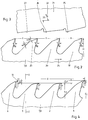
- raw teeth 19 and 20 (FIG. 2) are first produced on a raw strip 7, for example by a milling process.
- the raw teeth 19 and 20 can all have the same shape and the same raw tooth height H, as shown in FIG. 2.
- the raw teeth 19 and 20 can be arranged with a constant pitch t.
- the raw teeth 19 are already designed so that they have an assignment to the guide tooth 1, that is to say the raw teeth 19 are to be shaped into the guide teeth 1 during production, while the raw teeth 20 become secondary teeth 2, 3 , .. be reshaped.
- the raw teeth 20 can also have a different tooth height, in particular compared to the raw teeth 19.
- the raw teeth 19 and 20 are profiled with a matching positive raw chip angle gamma R and also have a first raw clearance angle ⁇ R1 and a second raw clearance angle ⁇ R2 .
- the implementation of these two different raw clearance angles is not absolutely necessary. It is also sufficient to create only one raw clearance angle by profiling.
- Fig. 3 a compression punch 21 is illustrated, which extends with its length over the length of a group 6 of teeth and is driven in a stroke-like manner according to double arrow 22.
- the direction of movement according to double arrow 22 is at an acute compression angle 23 to the band running direction 24 of the saw blade.
- the compression stamp 21 has a first working surface 25, the arrangement and design of which is assigned to the plastic deformation of the tooth tip of the raw tooth 19 to produce the cutting edge and the rake angle gamma 1 and the clearance angle ⁇ 1 of the guide tooth 1, in such a way that the tooth tip of the Guide tooth 1 with its section 11 also receives the tooth height h 1 at the same time.
- the compression stamp 21 has a second working surface 26 which is designed and arranged for the plastic deformation of the tooth tip of the raw tooth 20 for the purpose of producing the following tooth 2.
- the tooth tip or the cutting edge 12 of the follower tooth 2 is produced by plastic deformation, the rake angle gamma R corresponding to the extent of the plastically deformed area at the tip of the tooth resulting in the rake angle gamma 2 on the follower tooth 2.
- the tooth tip is deformed so that the follower tooth 2 receives the tooth height h 2 , that is, the tooth difference ⁇ h to the tooth height h 1 of the guide tooth 1 is generated.
- the raw tooth 20 forming the follower tooth 2 according to FIG. 2 could already have a lower tooth height than the raw tooth 19 after profiling, so that the tooth difference ⁇ h results partly from profiling, partly from the plastic deformation.
- the compression ram 21 also has a third working surface 27, which is assigned to the plastic deformation of the second raw tooth 20 (FIG. 2) and thus to the generation of the following tooth 3.
- the follower tooth 3 is given a tooth height h 3 and a rake angle gamma 3 .
- the follower teeth 2 and 3 are not exactly identical to one another, but that, due to the manufacturing process, there are tolerable differences during the profiling process (FIG. 2), but above all also during the upsetting process (FIG. 3) in slight or deliberately larger differences, especially in the heights h 2 and h 3 and the rake angles gamma 2 and gamma 3 . From Fig.
- the first working surface 25 is arranged comparatively recessed relative to the other two working surfaces 26 and 27, so that during an upsetting process the working surfaces 26 and 27 first come into contact with the tooth tips of the raw teeth 20 during this contact between the working surface 25 and the tooth tip of the raw tooth 19 only after a certain free stroke. Nevertheless, a plastic deformation carried out in this way means a common plastic deformation of the raw teeth 19, 20 in the tooth group 6, which therefore takes place more or less simultaneously. On the other hand, it is conceivable to subdivide the upsetting punch 21 and to control or coordinate the strokes of the individual parts accordingly.
- the different plastic deformation of the tooth tips of the raw teeth 19 and 20 can take place, for example, by upsetting, but also by rolling, the shaping then taking place more or less in succession. It is also conceivable that the compression punch 21 has a longer working length, so that it can plastically deform the raw teeth of two successive groups 6 at the same time, for example.
- the different plastic deformation of the tooth tips of the raw teeth 19 and 20 is essential. In addition to the height difference, there is an increase in the positive raw rake angle, rake angles on the guide tooth 1 and the follow teeth 2, 3,... That cannot be produced by milling alone.
- the burr that is present after profiling is also flipped over at each tooth tip in the direction of the strip running direction 24, which increases the sharpness of each tooth.
- this has a positive effect in reducing the vibration behavior of the saw band, in such a way that a different chip scale frequency arises, which not only ensures smooth running of the Saw band contributes during use, but is also favorable for the edge retention and lifespan of the saw blade.
- Fig. 5 shows an enlarged view of a guide tooth 1 or a follower tooth 2, 3, .., which was milled with a raw rake angle gamma R and two clearance angles ⁇ R1 and ⁇ R2 and then plastically deformed such that a positive in the area of its tooth tip 28 Rake angle gamma and a clearance angle ⁇ was generated, the wedge angle of the tooth tip 28 being essentially maintained.
- FIG. 6 shows a side view of a second embodiment of the saw blade, similar to the view according to FIG. 4.
- Four follower teeth 2, 3, 4, 5 in group 6 are assigned to one guide tooth 1 here.
- a variable division t 1 , t 2 , t 3 , t 4 and t 5 is used.
- the teeth are plastically deformed in different ways. There are slight differences in height between the following teeth 2, 3, 4, 5, while the difference in height ⁇ h to the guide tooth 1 is of a different order of magnitude.
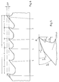
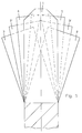
- the embodiment of the saw blade according to FIGS. 7 to 9 has a group 6 of seven teeth.
- Each group has 6 a guide tooth 1 and three pairs of follower teeth 2, 3; 4, 5 and 2 ', 3'. 7 and 8, auxiliary lines are shown.
- the auxiliary lines in FIG. 7 illustrate the different ones Tooth heights or height levels.
- the auxiliary lines in Fig. 8 clarify the different cabinet widths as an oversize Bandwidth. It can be seen that the pair of follower teeth 2, 3 the has the lowest tooth height and the largest cabinet width. This is also clear from the projection according to FIG. 9. It is also recognizable that the related secondary teeth 2 and 3 are not arranged in direct succession, but distributed anywhere in the group. In the pair of follower teeth 4 and 5 are those who have the following teeth have the greatest height.
- the height of the follower teeth 4 and 5 is not exactly the same, but forms a height difference ⁇ h to that Height of the guide teeth 1.
- the follower teeth 4 and 5 are on one first height level arranged opposite the guide teeth 1. It there are two more belonging to each other in group 6 Subsequent teeth 2 'and 3', the height of which is between the pairs of Subsequent teeth 2, 3 and 4, 5 is arranged.
- The is accordingly Cabinet width trained.
- the Grading step i.e. the height difference from a height level to the neighboring level in particular directly above the entire height grading can be carried out. That applies to the Cabinet width gradation.
- the arrangement of the teeth in the group is any. It makes sense to switch from one to the right set secondary tooth to a left set tooth etc. to maintain. But even this condition doesn't have to be fulfilled.
- Fig. 9 shows that it is in terms of the clearance of the Cut channel only depends on the projection of the teeth.
- the order of the teeth in the group is arbitrary. Every tooth only works with its cut edge section, the side protrudes beyond the projection of the other teeth. To this In this way, chips are removed in strip form from the cutting channel, that lie side by side in the projection and do not overlap each other. These stripes are due to the uniform gradation of the cabinet width equally wide. It is also recognizable as the load roughly evenly on everyone Teeth is distributed in the group.
- the production of the saw blade according to FIGS. 7 to 9 can be done in the way that first the profiling of all Raw teeth, for example, by milling with a rake angle of 10 ° and a matching raw tooth height. With this Profiling is only pre-formed the variable division. Then all teeth are plastically deformed, which are useful in a common deformation step for all teeth of the group is carried out, with the individual teeth, however, very different deformations arise.
- the guide tooth 1 is equipped with a Height difference of 0.15 mm compared to the raw tooth height and thereby gets a rake angle in the area of his Tip of z. B. 15 °.
- the tip of the guide tooth 1 is located with it at a first level.
- the pair of follower teeth 4, 5 is shaped down more than the guide tooth lands at a height level that is different from the height of the raw tooth differs by, for example, 0.20 mm.
- the following teeth 4, 5 get a rake angle of 17 °, for example Area of their tooth tips.
- the ones created during profiling Tolerances between the raw teeth are deliberately allowed or exploited, such that the secondary teeth 4, 5 after the plastic Deformation is not exactly at the same level and also do not have exactly the same rake angle. Also here differences, of course of a different magnitude, between the related teeth 4 and 5 authorized.
- the further pair of follower teeth 2 ', 3' is, for example formed from the raw tooth height to a further height level, which is 0.25 mm lower than the raw tooth height.
- the target rake angle here is, for example, 19 °.
- the Pair of follower teeth 2, 3, which after plastic deformation is located at the lowest level, has one Height difference of, for example, 0.30 mm to the raw tooth height.
- the target rake angle is 21 °.
- You can recognize this Example that the levels between the individual height levels are dimensioned the same, namely 0.05 mm.
- the grading of the rake angle the difference is 2 °. Of course you can too Appropriate tolerances are permitted here, for example of ⁇ 1 °.
- the pair of follower teeth 2, 3 is the one that was plastically deformed the most. If the material of the Band does not participate in such a deformation or the risk of If there are any fractures, it is recommended to adjust the raw tooth height Teeth that form the follower teeth 2, 3 already during profiling to be less than the raw tooth height of the remaining teeth, thus the relative deformation on the secondary teeth 2, 3 less becomes. The same can also be done for other pairs of secondary teeth be considered.
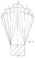
- 10 to 12 is another embodiment of a Saw blade shown with a group of eight teeth.
- many things are right with the embodiment 7 to 9, which is why reference is made to this can be.
- the even number of teeth in the group results, however, from the fact that the guide tooth 1 in the form of a another guide tooth 1 appears a second time in the group.
- the further guide tooth 1 can be approximately in the middle of the Group arranged.
- the teeth are with variable pitch arranged.
- Fig. 10 shows that the gradation of the height is not the same Steps, but carried out here in different steps is.
- the enlarged view leaves the mutual Recognize relation. Between the shaped guide teeth 1 and the largest follower teeth 4, 5 there is only a small difference in height.
- the respective height difference to the secondary teeth 2 ', 3 ' is already bigger and the last height difference from the follower teeth 2 ', 3' to the secondary teeth 2, 3 is even larger. It is but also possible, the height differences different and in to implement another order, for example falling or irregular.
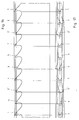
- FIG. 11 shows an uneven, falling gradation of the cabinet width, their course can be seen better in the enlarged view is.
- the smallest step is between the secondary teeth 2 ', 3' and the follower teeth 2, 3, i.e. on the outside of the belt. With that the chips that clear the secondary teeth 2, 3 from the cutting channel, deliberately kept narrow. This improves the quality of the Surface of the cut workpiece.
- the grading of Cabinet width can also be increased or combined rising and falling.
- the projection representation of the teeth according to FIG. 12 is correct basically corresponds to the projection representation according to FIG. 9.
- the guide teeth 1 are identical and cover yourself. The different heights and the different Cabinet width grading can also be seen here.
- Group of teeth also made up of eight teeth, however, are here two different guide teeth 1 'and 1' 'immediately arranged one after the other at the beginning of the group.
- the pairs of Subsequent teeth are arranged one behind the other according to their height gradation.
- the pair of follower teeth follows 4, 5 with the greatest height of the follower teeth.
- Variable division is also implemented here. Of course, constant division could also be used be realized.
- the order is Any teeth in the group.
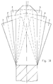
- the embodiment of the saw blade according to FIGS. 16 to 18 has nine teeth in the group.
- the guide tooth 1 is arranged three times in the group. From the follow teeth there are two between two guide teeth, whereby these are enclosed by two adjacent guide teeth Subsequent teeth belong to different pairs. But here too 18 matches the projection representation 9 in accordance with the drawing.
Abstract
Description
Die Erfindung bezieht sich auf ein Sägeblatt mit einer sich wiederholenden Gruppe von Zähnen, die aus einem ungeschränkten gephasten Führungszahn mit einem im Vergleich zu seiner Breite kleineren, in der Mitte seiner Zahnspitze angeordneten wirksamen Schnittkantenabschnitt und einer vorzugsweise geraden Anzahl geschränkter Folgezähne besteht, wobei der Führungszahn eine größere Zahnhöhe als jeder der Folgezähne aufweist. Die Erfindung kann sowohl bei einem Bandsägeblatt, also einem Sägeblatt mit linearer Anordnung der Zähne hintereinander, als auch bei einem Kreissägeblatt angewendet werden. Es ist in der Regel nur ein einziger Führungszahn in der Gruppe vorgesehen. Die Folgezähne können untereinander gleiche, aber auch ungleiche - insbesondere paarweise - Zahnhöhe aufweisen. Die Erfindung läßt sich insbesondere an einem Grundband aus Bimetall anwenden. The invention relates to a saw blade with one repeating group of teeth coming from an unrestricted chamfered guide tooth with a compared to its width smaller effective ones located in the middle of its tooth tip Cut edge section and a preferably even number set follower teeth, the guide tooth one has a larger tooth height than each of the follower teeth. The invention can be used with a band saw blade, i.e. a saw blade with a linear arrangement of the teeth one behind the other, as well a circular saw blade. It is usually only a single guide tooth is provided in the group. The Subsequent teeth can be the same, but also different - especially in pairs - have tooth height. The invention leaves apply in particular to a bimetal base tape.
Aus der DE 43 24 411 A1 ist ein Sägeblatt der eingangs beschriebenen Art bekannt, welches an einem Grundkörper sowohl ungeschränkte als auch geschränkte Zähne aufweist, deren Zahnspitzen aus einem Material bestehen, das härter als das Material des Grundkörpers ist. Es kann sich dabei z.B. um Wolframcarbid, aber auch um Schnellstahl handeln. Die Zähne sind in sich wiederholender Gruppe angeordnet, wobei die kleinste Gruppe aus einem geraden Führungszahn und zwei nach rechts und links geschränkten Folgezähnen besteht. Der Führungszahn besitzt eine Zahnhöhe, die größer ist als die gemeinsame Zahnhöhe der beiden Folgezähne. Der Führungszahn ist gephast, besitzt also in der Mitte der Zahnspitze einen gerade verlaufenden Schnittkantenabschnitt, an den sich in symmetrischer Anordnung rechts und links je ein geneigt verlaufender Schnittkantenabschnitt anschließt. Der Unterschied in der Zahnhöhe zwischen dem Führungszahn und den Folgezähnen sowie der Phasenwinkel sind derart groß gewählt, daß in der Projektion der Zähne in Bandlaufrichtung die inneren Ecken der Folgezähne innerhalb des Umrisses des Führungszahns und die äußeren Ecken des Führungszahn innerhalb der Umrisse der Folgezähne liegen, so daß die jeweils abgeschatteten Ecken nicht arbeiten. Die Schnittkanten sämtlicher Zähne sind durch Schleifen hergestellt, also durch eine zwar präzise aber auch aufwendige Formgebung, die auch die beiden unterschiedlichen Zahnhöhen erbringt.From DE 43 24 411 A1 a saw blade is described Kind known, which on a base body both unrestricted as well as set teeth, the tips of their teeth consist of a material that is harder than the material of the Basic body is. It can e.g. around tungsten carbide, however also act on high-speed steel. The teeth are repetitive Group arranged, the smallest group of one straight guide tooth and two set right and left Subsequent teeth exist. The guide tooth has a tooth height that is greater than the common tooth height of the two secondary teeth. The guide tooth is phased, so it has in the middle Tooth tip a straight cutting edge section which are arranged in a symmetrical arrangement on the right and left sloping cut edge section connects. Of the Difference in tooth height between the leading tooth and the Subsequent teeth and the phase angle are chosen so large that in the projection of the teeth in the tape running direction the inner ones Corners of the follower teeth within the outline of the guide tooth and the outer corners of the guide tooth within the outline of the Subsequent teeth lie so that the shaded corners are not work. The cut edges of all teeth are through Grinding manufactured, so through a precise but also elaborate design that also the two different Yields tooth heights.
Auch aus der DE 36 11 063 A1 ist ein Sägeblatt der eingangs beschriebenen Art mit einer Gruppe von Zähnen aus einem Führungszahn und mehreren Folgezähnen bekannt, die in sich wiederholenden Zyklen vorgesehen sind. Der Führungszahn besitzt dabei die größte Höhe und die Zahnhöhe nimmt in der Gruppe ab, kann aber an den Folgezähnen auch gleich sein. Die Folgezähne sind als geschränkte Zähne ausgebildet und in der Regel abwechselnd nach links und rechts geschränkt vorgesehen, um auf diese Art und Weise die Breite des Schnittkanals größer zu gestalten als die Breite des Grundkörpers des Sägeblatts. Der Führungszahn kann auch gephast sein. Die Herstellung der unterschiedlich hohen Zähne erfolgt durch einen entsprechenden Fräsvorgang oder mit einem Werkzeug, bei dem die Zahnspitzen durch eine Schlagkraft in Laufrichtung des Sägebandes gebogen werden. Es schließt sich ein Schleifvorgang an, um die Schnittkanten der Zähne mit der vorgesehenen Höhenstufung zu erzeugen. Der wirksame Anteil der geschliffenen Schnittkanten nimmt in ihrer Länge von Zahn zu Zahn in der Gruppe ab, so daß die wesentliche Schnittarbeit von dem Führungszahn zu leisten ist und die beiden Folgezähne im wesentlichen nur eine Verbreiterung des Schnittkanals bewirken, damit ein Freischnitt erreicht wird.From DE 36 11 063 A1 is a saw blade at the beginning described type with a group of teeth from one Guide tooth and several secondary teeth known in themselves repetitive cycles are provided. The guide tooth has the greatest height and the tooth height decreases in the group, but can also be the same on the following teeth. The follow teeth are designed as set teeth and are usually alternating slanted to the left and right provided to this Way to make the width of the cutting channel larger than the width of the body of the saw blade. The leading tooth can also be phased. The production of different heights Teeth are made by an appropriate milling process or with a tool where the tooth tips are driven by an impact be bent in the direction of the saw band. It closes a grinding process takes place around the cut edges of the teeth to generate the intended height gradation. The effective part the length of the ground cutting edges increases in tooth length Tooth in the group, so that the essential cutting work of the leading tooth is to be performed and the two secondary teeth in the essentially only widen the cutting channel, so that a free cut is achieved.
Aus der DE 33 00 791 C2 ist ein Sägeblatt mit sich wiederholenden Gruppen von Zähnen aus mehreren aufeinanderfolgenden hohen und mehreren auffeinanderfolgenden niedrigen Zähnen bekannt. Die erste Gruppe aus gleich hohen Zähne enthält geschränkte und ungeschränkte Zähne. Die zweite Gruppe aus gleich niedrigen Zähne enthält ebenfalls geschränkte und ungeschränkte Zähne. Jede Gruppe kann aber auch Zähne beider Höhen aufweisen. Jeder Zahn weist erste und zweite, voneinander unterschiedliche Spanwinkel und erste und zweite, voneinander unterschiedliche Freiwinkel auf. Die beiden unterschiedlichen Span- und Freiwinkel können an jedem einzelnen Zahn durch plastische Verformung der Zahnspitze, insbesondere durch einen Stauchvorgang, mit einem Druckstempel erzeugt werden, der unter einem spitzen Winkel zur Laufrichtung des Sägebandes bewegt wird. Dabei verringert sich auch die Zahnhöhe. Das Maß der Stauchung kann durch Einstellen oder Steuern des Hubes des Druckstempels eingestellt oder gesteuert werden. Die Formgebung der Zähne kann auch ohne Stauchen durch Fräsen oder Schleifen erfolgen. Durch die plastische Verformung eines Zahnes nach dem anderen kann eine Folge von Zähnen gebildet werden, bei der zwischen den hohen Zähnen der ersten Gruppe und den niedrigen Zähnen der zweiten Gruppe eine Höhendifferenz besteht und die beiden Spanwinkel und die beiden Freiwinkel an jedem Zahn erzeugt werden. Auch unterschiedliche Einschweiftiefen und unterschiedliche Teilungen können innerhalb jeder der beiden Gruppen verwirklicht werden. Es ist nicht erkennbar, ob die hohen und die niedrigen Zähne durch die plastische Verformung unterschiedliche oder gleiche Spanwinkel erhalten. Weiter bleibt offen, ob die nach der plastischen Verformung entstehende Höhendifferenz der Zähne bei einem vorangehenden Fräsvorgang vorgebildet wird oder nicht.From DE 33 00 791 C2 is a saw blade with repetitive Groups of teeth from several consecutive high and several successive low teeth. The first group of teeth of equal height contains set and unrestricted Teeth. The second group of equally low teeth also contains set and unrestricted teeth. Each Group can also have teeth of both heights. Every tooth has first and second, different rake angles and first and second, different clearance angles on. The two different rake and clearance angles can be on each individual tooth through plastic deformation of the tooth tip, in particular by an upsetting process with a pressure stamp are generated at an acute angle to the direction of travel of the saw band is moved. The tooth height is also reduced. The degree of compression can be adjusted or controlled of the stroke of the pressure stamp can be set or controlled. The shape of the teeth can also be cut without milling or grinding. Due to the plastic deformation of a Tooth after tooth a series of teeth can be formed in the between the high teeth of the first group and the low teeth of the second group there is a height difference and the two rake angles and the two relief angles on each Tooth are generated. Also different penetration depths and different divisions can exist within each of the two Groups are realized. It is not recognizable whether the high and low teeth due to the plastic deformation receive different or the same rake angle. Remains on It is not clear whether the height difference that occurs after the plastic deformation the teeth are pre-formed during a previous milling process will or not.
Der Erfindung liegt die Aufgabe zugrunde, ein vergleichsweise einfach herstellbares Sägeblatt der eingangs beschriebenen Art bereitzustellen, welches vorteilhaft sehr große Spanwinkel aufweist, ein reduziertes Schwingungverhalten besitzt und bei dessen Gebrauch eine unterschiedliche Spanschuppenfrequenz entsteht.The invention is based, a comparative task Easy to manufacture saw blade of the type described in the introduction to provide which is advantageously very large rake angle has a reduced vibration behavior and at its use a different chip scale frequency arises.
Erfindungsgemäß wird dies bei einem Sägeblatt der eingangs beschriebenen Art dadurch erreicht, daß jedenfalls alle Folgezähne im Bereich ihrer Zahnspitzen je eine untereinander unterschiedliche plastische Verformung durch Materialverlagerung in Bandlaufrichtung aufweisen, und daß jeder Folgezahn durch die unterschiedliche plastische Verformung einerseits je einen vergrößerten positiven Spanwinkel und andererseits jeweils eine gegenüber dem Führungszahn verringerte Zahnhöhe aufweist.According to the invention, this is the case with a saw blade described type achieved in that in any case all follower teeth in the area of their tooth tips one different from each other plastic deformation due to material displacement in Have tape running direction, and that each follower tooth through the different plastic deformation on the one hand increased positive rake angle and on the other hand one has reduced tooth height compared to the guide tooth.
Die Erfindung geht von dem Gedanken aus, mindestens an den Folgezähnen in erster Linie durch die unterschiedliche plastische Verformung der betreffenden profilierten Zahnspitzen letztlich unterschiedliche positive Spanwinkel zu bilden. Die Profilierung der Zähne vor der plastischen Verformung kann insbesondere durch Fräsen, aber auch durch Schleifen oder Stanzen oder auch durch energiereiche Strahlverfahren erfolgen. Unter "unterschiedlich" werden einerseits bereits solche Unterschiede verstanden, die infolge herstellungsbedingter Toleranzen auftreten bzw. unvermeidbar sind. So können z.B. bereits bei der Herstellung des Fräsers oder der profilierten Schleifscheiben größere Toleranzen zugelassen werden. Während bisher angestrebt wird, die Toleranzen möglichst klein zu halten, nutzt die Erfindung den gegenteiligen Weg. Gleiches gilt für die Herstellung und den Antrieb sowie die Steuerung des Werkzeuges für die plastische Verformung. Andererseits können aber auch vergleichsweise größere Unterschiede zugelassen bzw. bewußt angetrebt werden, beispielsweise dadurch, daß die Folgezähne bereits mit unterschiedlichen Zahnhöhen, insbesondere paarweise auf unterschiedlichen Höhenniveaus, profiliert und unter Anwendung gleicher oder ungleicher Verformungshübe die Zahnspitzen unterschiedlich plastisch verformt werden. Die dabei nach der plastischen Verformung erreichbaren positiven Spanwinkel sind in der Regel vorteilhaft größer als die allein durch einen Fräs- oder Schleifvorgang mit Hinterschnitt erzielbaren positiven Spanwinkel. Die unterschiedliche plastische Verformung zumindest der Folgezähne geschieht durch eine Materialverdrängung oder -verlagerung in der Hauptebene des Sägeblattes. Die Materialverdrängung erfolgt in der Regel schräg zur Bandlaufrichtung, also mit einer sich in Bandlaufrichtung auswirkenden Komponente, sodaß das Material im Bereich der Zahnspitzen der Folgezähne volumenkonstant in eine andere Lage gebracht wird. Dabei entstehen gleichzeitig zwei wesentliche Merkmale, nämlich ein in positiver Richtung vergrößerter Spanwinkel und eine verringerte Höhe oder verringerte Höhen an den Folgezähnen, immer im Vergleich zu den Rohzähnen nach deren Profilierung. Besonders vorteilhaft ist es, wenn die Folgezähne paarweise unterschiedlich plastisch verformt werden. Dabei können die Paare von Folgezähnen auf unterschiedlichen Höhenniveaus zueinander und zu dem oder den Führungszähnen plastisch verformt werden. Die unterschiedliche plastische Verformung der Paare von Folgezähnen auf unterschiedlichen gestuften Höhenniveaus wird immer in Abstimmung auf unterschiedliche Schränkweiten vorgenommen. Das Paar von Folgezähnen, welches auf dem kleinsten Höhenniveau angeordnet ist, besitzt dabei die größte Schränkweite. Das Paar von Folgezähnen, welches auf dem größten Höhenniveau angeordnet ist, besitzt dabei die geringste oder kleinste Schränkweite. Die Paare von Folgezähnen, die höhenmäßig dazwischen angeordnet sind, besitzen auch eine dazwischenliegende Schränkweite. Dies alles hat mit der Reihenfolge der Zähne in der Gruppe nichts zu tun. Innerhalb der Gruppe ist die Reihenfolge der Zähne, also des oder der geraden Führungszähne und der geschränkten Folgezähne, beliebig. Es kommt nur auf die Projektion der Zähne in Bandlaufrichtung an. Selbst die beiden Zähne eines Paares von Folgezähnen müssen nicht unmittelbar aufeinanderfolgend in der Gruppe angeordnet sein. Die beiden Zähne eines zusammengehörigen Paares von Folgezähnen, die auf (etwa) gleichem Höhenniveau angeordnet sind, können durch einen Führungszahn getrennt sein. Es ist durchaus nicht nachteilig, wenn die beiden Zähne eines zusammengehörigen Paares von Folgezähnen, die auf (etwa) gleichem Höhenniveau angeordnet sind, im Vergleich zueinander (etwas) unterschiedliche Spanwinkel und (etwas) unterschiedliche Höhen aufweisen. In allen Fällen werden die Folgezähne nach der plastischen Verformung nicht geschliffen, aber nachfolgend an die plastische Verformung der Zahnspitzen geschränkt.The invention is based on the idea, at least on the follower teeth primarily due to the different plastic Ultimately deformation of the profiled tooth tips concerned to form different positive rake angles. The profiling of the teeth before plastic deformation can be caused in particular by Milling, but also by grinding or punching or by high-energy blasting processes are carried out. Under "different" on the one hand, such differences are already understood that occur due to manufacturing tolerances or unavoidable are. For example, already in the manufacture of the Cutter or the profiled grinding wheels larger tolerances be allowed. While striving so far, the tolerances To keep it as small as possible, the invention uses the opposite Path. The same applies to the production and the drive as well as the control of the tool for plastic deformation. On the other hand, there can also be comparatively larger differences be allowed or sought consciously, for example in that the follower teeth already with different Tooth heights, especially in pairs at different height levels, profiled and using the same or different Deformation strokes the tooth tips differently plastic be deformed. The ones that can be achieved after plastic deformation positive rake angles are usually advantageous larger than that with just a milling or grinding process Undercut achievable positive rake angle. The different plastic deformation occurs at least in the secondary teeth due to material displacement or displacement in the main level of the saw blade. The material displacement takes place in the Usually at an angle to the tape running direction, i.e. with one in the tape running direction impacting component, so that the material in Area of the tooth tips of the follower teeth in a constant volume different situation is brought. This creates two at the same time essential features, namely an enlarged in the positive direction Rake angle and a reduced height or reduced Heights on the following teeth, always in comparison to the raw teeth after their profiling. It is particularly advantageous if the Follower teeth are plastically deformed in pairs differently. The pairs of secondary teeth can be at different height levels to each other and to the guide tooth (s) be deformed. The different plastic deformation of pairs of follower teeth on different graded levels Height levels will always be in coordination with different ones Cabinet widths made. The pair of follow teeth, which on the smallest height level, has the largest cabinet width. The pair of follow teeth, which on the greatest height level, has the lowest or smallest cabinet width. The pairs of follow teeth that arranged in terms of height, also have an intermediate one Cabinet width. All of this has to do with the order of teeth in the group doing nothing. Is within the group the order of the teeth, i.e. the straight guide tooth or teeth and the set secondary teeth, any. It only comes on the projection of the teeth in the direction of tape travel. Even the Both teeth of a pair of follower teeth do not have to be immediate be arranged consecutively in the group. The two Teeth of a related pair of follow teeth that are on (about) the same height level can be arranged by a Guide tooth must be separated. It’s not a disadvantage if the two teeth of an associated pair of follow teeth, which are arranged at (approximately) the same level, in Comparison of (somewhat) different rake angles and have (somewhat) different heights. In all cases the secondary teeth are not ground after the plastic deformation, but following the plastic deformation of the tooth tips limited.
Das erfindungsgemäße Sägeblatt weist eine Reihe von Vorteilen auf. Durch die unterschiedlichen Spanwinkel infolge unterschiedlicher plastischer Verformung unter Zulassung größerer Toleranzen reduziert sich das Schwingungsverhalten des Sägeblattes beim Sägen dahingehend, daß eine unterschiedliche Spanschuppenfrequenz entsteht. Es sind extrem große positive Spanwinkel erreichbar, die durch einen Fräs- oder Schleifvorgang allein nicht herstellbar sind. Durch die plastische Verformung der Zahnspitzen, die z.B. durch Stauchen oder Rollen, erreicht werden kann, bekommt die profilierte Schnittkante eine größere Schärfe. Dabei wird auch der beim Fräsen oder Schleifen gebildete Grat in Laufrichtung des Sägeblattes umgelegt. Das erfindungsgemäße Sägeblatt läßt sich schließlich sehr einfach und preisgünstig herstellen, insbesondere dadurch, daß die Folgezähne in einer oder mehreren Gruppen gemeinsam bzw. weitgehend gleichzeitig plastisch verformt werden. Die unterschiedliche plastische Verformung kann auf unterschiedlichen Höhenniveaus durchgeführt werden. Diese unterschiedlichen Höhenniveaus können durch eine proportionale Stufung miteinander verbunden sein. Beispielsweise ist es für eine Gruppe von 7 Zähnen sinnvoll, den Führungszahn, der nach der Profilierung einen Spanwinkel von etwa 10° aufweisen kann, plastisch so zu verformen, daß er danach einen Spanwinkel von etwa 15° aufweist. Der Führungszahn weist die größte Höhe auf. Die Folgezähne können nach der Profilierung ebenfalls einen Spanwinkel von 10° aufweisen. Das erste Paar Folgezähne wird vergleichsweise stärker plastisch verformt. Es bekommt einen Spanwinkel von etwa 17°, eine Höhendifferenz -x gegenüber dem Führungszahn und eine Schränkweite (abzüglich Bandbreite) von etwa einem Drittel der maximalen Schränkweite des am meisten verformten Paares von Folgezähnen. Das zweite Paar Folgezähne wird vergleichsweise noch stärker plastisch verformt. Es bekommt einen Spanwinkel von etwa 19°, eine Höhendifferenz -2x gegenüber dem Führungszahn und eine Schränkweite von etwa zwei Drittel der maximalen Schränkweite des am meisten verformten Paares von Folgezähnen. Das dritte Paar Folgezähne wird vergleichsweise am stärksten plastisch verformt. Es bekommt einen Spanwinkel von etwa 21°, eine Höhendifferenz -3x gegenüber dem Führungszahn und die maximale Schränkweite. Die Reihenfolge der Zähne in der Gruppe ist beliebig. Entsprechendes gilt für andere Zähnezahlen in der Gruppe. Die Folgezähne weisen links und rechts geschränkte Zähne auf, die paarweise auf gleichem Höhenniveau und mit derartiger Schränkung angeordnet sind, daß in der Projektion sämtlicher Zähne in Bandrichtung jeweils paarweise diskrete Zerspanungsbereiche entstehen, die sich nicht mit Zerspanungsbereichen anderer Zähne überlappen. Die Zerspanungsbereiche der Zähne schließen seitlich aneinander an.The saw blade according to the invention has a number of advantages on. Due to the different rake angles due to different plastic deformation while allowing larger tolerances the vibration behavior of the saw blade reduces Sawing in that a different chip scale frequency arises. Extremely large positive rake angles can be achieved not by milling or grinding alone are producible. Due to the plastic deformation of the tooth tips, e.g. can be achieved by upsetting or rolling, the profiled cutting edge gets a greater sharpness. Here the burr formed during milling or grinding in the direction of travel of the saw blade folded. The saw blade according to the invention can finally be produced very easily and inexpensively, in particular in that the follower teeth in one or several groups together or largely simultaneously be plastically deformed. The different plastic deformation can be performed at different levels become. These different height levels can be determined by a proportional gradation. For example it makes sense for a group of 7 teeth, the guide tooth, which have a rake angle of about 10 ° after profiling can plastically deform so that he then one Rake angle of about 15 °. The guide tooth shows the greatest height at. The follower teeth can after the profiling also have a rake angle of 10 °. The first couple Follower teeth are plastically deformed comparatively more. It gets a rake angle of about 17 °, a height difference -x opposite the guide tooth and a cabinet width (minus Bandwidth) of about a third of the maximum cabinet width of the most deformed pair of follower teeth. The second A pair of follower teeth is plastically deformed even more comparatively. It has a rake angle of around 19 °, a height difference -2x compared to the guide tooth and a cabinet width of about two thirds of the maximum cabinet width of the most deformed pair of follower teeth. The third pair of follower teeth is comparatively most plastically deformed. It gets a rake angle of about 21 °, a height difference -3x opposite the guide tooth and the maximum set width. The chronological order the teeth in the group are arbitrary. The same applies to other number of teeth in the group. The following teeth point to the left and right set teeth, in pairs on the same Height level and are arranged with such limitation that in the projection of all teeth in the band direction in pairs discrete machining areas arise that are not compatible with Machining areas of other teeth overlap. The machining areas of the teeth adjoin one another laterally.
Auch der Führungszahn kann im Bereich seiner Zahnspitze eine im Vergleich zu der Verformung der Folgezähne unterschiedliche plastische Verformung aufweisen, so daß er durch die plastische Verformung einerseits einen vergrößerten positiven Spanwinkel und andererseits gegenüber den Folgezähnen eine vergleichsweise weniger verringerte Zahnhöhe aufweist. Die Herstellung der Rohzähne in der Gruppe erfolgt durch einen Fräsvorgang, wobei insbesondere sämtliche Zähne einer Gruppe gemeinsam gefräst werden Die so erzeugten Rohzähne können übereinstimmende, aber auch unterschiedliche Gestalt aufweisen, insbesondere hinsichtlich der Zahnhöhe und/oder eines oder mehrerer positiver oder neutraler Spanwinkel sowie Freiwinkel.The guide tooth can also be in the area of its tooth tip Different compared to the deformation of the follower teeth have plastic deformation so that it is due to the plastic Deformation on the one hand an enlarged positive rake angle and on the other hand, a comparative compared to the follower teeth has less reduced tooth height. The manufacture of the Raw teeth in the group are made by a milling process, whereby in particular, all teeth of a group are milled together The raw teeth produced in this way can match, but also have different shapes, particularly with regard to the tooth height and / or one or more positive or neutral rake angle and clearance angle.
Der Führungszahn kann im Bereich seiner Zahnspitze einen positiven Spanwinkel im Bereich zwischen 5° und 25° - insbesondere etwa 15° - und die Folgezähne im Bereich ihrer Zahnspitzen positive Spanwinkel im Bereich zwischen 5° und 30° - insbesondere etwa zwischen 17° und 21° - aufweisen. Die wirksamen Spanwinkel der Folgezähne sind in der Regel größer als der wirksame Spanwinkel des Führungszahns, weil die Folgezähne in der Regel stärker plastisch verformt sind als der Führungszahn. Dies kann auf der Höhendifferenz basieren. Insbesondere können die Folgezähne paarweise gestuft auf unterschiedliche Höhenniveaus plastisch verformt sein, wobei abnehmende absolute Zahnhöhe mit zunehmender Schränkweite kombiniert ist. Es ist aber auch möglich, die Rohzähne bereits mit unterschiedlichen Rohspanwinkeln zu fräsen, und zwar unter Einhaltung gleicher oder ungleicher Keilwinkel zwischen Spanwinkel und Freiwinkel.The guide tooth can be a positive one in the area of its tooth tip Rake angle in the range between 5 ° and 25 ° - in particular about 15 ° - and the secondary teeth in the area of their tooth tips positive Rake angle in the range between 5 ° and 30 ° - in particular approximately between 17 ° and 21 °. The effective rake angle of the following teeth are usually larger than the effective rake angle of the guide tooth because the follower teeth are usually stronger are plastically deformed than the guide tooth. This can be due to based on the height difference. In particular, the secondary teeth plastically graded in pairs to different height levels be deformed, with decreasing absolute tooth height with increasing Cabinet width is combined. But it is also possible that Milling raw teeth with different raw chip angles, namely while maintaining the same or different wedge angles between rake angle and clearance angle.
Das Sägeblatt kann zwischen der Zahnhöhe des Führungszahns und der Zahnhöhe eines Folgezahns eine Höhendifferenz im Bereich von etwa 0,05 bis 0,30 mm - insbesondere zwischen 0,08 und 0,15 mm - aufweisen. Diese Höhendifferenz kann beim Profilieren der Rohzähne ganz oder teilweise vorgebildet werden. Die endgültige Höhendifferenz ergibt sich jedoch nach der plastischen Verformung der Zahnspitzen bzw. nach dem Schränken der Folgezähne. Unter der Zahnhöhe der geschränkten Folgezähne kann die mittlere Zahnhöhe oder die maximale Zahnhöhe, also die Zahnhöhe der inneren Ecke des geschränkten Folgezahns verstanden werden. Die Höhendifferenz sollte nicht allzu groß gewählt werden, um den von dem Führungszahn ausgeräumten Span nicht allzu dick zu machen. Wenn Folgezähne paarweise auf unterschiedliche Höhenniveaus bzw. in unterschiedliche Ebenen unterschiedlich plastisch verformt werden, darf die maximale Verformung der beiden kleinsten Folgezähne das plastische Verformungsvermögen der Zähne nicht überschreiten.The saw blade can be between the tooth height of the guide tooth and the tooth height of a follower tooth a height difference in the range of about 0.05 to 0.30 mm - in particular between 0.08 and 0.15 mm - exhibit. This difference in height can occur when profiling the raw teeth be fully or partially pre-trained. The final However, the difference in height results from the plastic deformation the tooth tips or after setting the secondary teeth. The middle tooth can be found below the tooth height of the set secondary teeth Tooth height or the maximum tooth height, i.e. the tooth height of the inner corner of the set follower tooth can be understood. The Height difference should not be chosen too large to the chip cleared from the guide tooth is not too thick do. If follow teeth in pairs on different Height levels or different in different levels plastically deformed, the maximum deformation of the the two smallest secondary teeth the plastic deformability of teeth not exceed.
Der Führungszahn kann einen Phasenwinkel im Bereich zwischen 30° und 60° aufweisen. Die Ausbildung und Anordnung der Phase kann so getroffen sein, daß nur etwa die äußere Hälfte jedes geschränkten Folgezahns und/oder die innere Hälfte der durch die Phase gebildeten Schnittkante des Führungszahns arbeitet. Dies gilt für die beiden sich einem Führungszahn unmittelbar anschließenden Folgezähne in der Gruppe.The guide tooth can have a phase angle in the range between 30 ° and have 60 °. The training and arrangement of the phase can be made so that only about the outer half of each set Follower tooth and / or the inner half of the through the Phase formed cutting edge of the guide tooth works. This applies to the two immediately following a guide tooth Followers in the group.
In allen Ausführungsformen kann der Phasenwinkel des Führungszahns und die Schränkweite der Folgezähne so aufeinander abgestimmt sein, daß die Belastung des Sägeblattes in etwa gleichmäßig auf die Zähne verteilt ist.In all embodiments, the phase angle of the guide tooth and the set width of the follower teeth on top of each other be coordinated that the load on the saw blade in about is evenly distributed on the teeth.
Das Verfahren zur Herstellung eines Sägeblattes zur Herstellung eines Sägeblattes mit einer sich wiederholenden Gruppe von Zähnen, die aus einem ungeschränkten gephasten Führungszahn mit einem in der Mitte seiner Zahnspitze gerade verlaufenden Schnittkantenabschnitt und einer vorzugsweise geraden Anzahl geschränkter Folgezähne besteht, wobei der Führungszahn eine größere Zahnhöhe als jeder der Folgezähne aufweist, kennzeichnet sich erfindungsgemäß dadurch, daß zunächst die Zähne als Rohzähne profiliert werden, daß dann die Zahnspitzen zumindest der Folgezähne durch Materialverlagerung in Bandlaufrichtung so unterschiedlich plastisch verformt werden, daß jeder Folgezahn durch die unterschiedliche plastische Verformung einerseits je einen vergrößerten positiven Spanwinkel und andererseits jeweils die gegenüber dem Führungszahn verringerte Zahnhöhe aufweist, und so ein Führungszahn und mehrere Folgezähne in der Gruppe gebildet werden, und daß der Führungszahn in der Gruppe durch Schleifen gephast und die Folgezähne geschränkt werden.The process of making a saw blade for making a saw blade with a repeating group of teeth, that from an unrestrained phased guide tooth with a cut edge section running straight in the middle of its tooth tip and a preferably even number of restricted ones Follower teeth exist, the guide tooth being a larger one Tooth height than each of the follower teeth shows according to the invention in that first the teeth as raw teeth be profiled so that the tooth tips at least of the follower teeth so different due to material displacement in the direction of belt travel be plastically deformed so that each follower tooth through the different plastic deformation on the one hand increased positive rake angle and on the other hand each has reduced tooth height compared to the guide tooth, and so one guide tooth and several follower teeth are formed in the group and that the guide tooth in the group by grinding be phased and the secondary teeth set.
Im Ablauf der Herstellung wird zunächst das Rohband aus Bimetall in an sich bekannter Weise so profiliert, z.B. gefräst, daß die Rohzähne entstehen. Das Rohband wird abschnittweise profiliert, so daß pro Abschnitt mehrere Rohzähne gleichzeitig entstehen. Die Anzahl der Rohzähne kann zweckmäßig mit der Anzahl der Zähne in der Gruppe übereinstimmen. Besonders einfach ist es, wenn sämtliche Rohzähne mit gleicher Gestalt und gleicher Zahnhöhe profiliert werden und sich nur die herstellungsbedingten Toleranzen auswirken, die allerdings bewußt zugelassen werden, ja sogar erwünscht sind. Es folgt dann die unterschiedliche plastische Verformung der Zahnspitzen der Zähne, wobei aus den Rohzähnen Führungszähne und Folgezähne werden. Auch dabei können und sollen sich herstellungsbedingten Toleranzen auswirken, die bewußt zugelassen werden, ja sogar erwünscht sind. Der Führungszahn und die Folgezähne in der Gruppe bekommen so relativ große, unterschiedliche positive Spanwinkel und unterschiedliche Zahnhöhen, wobei die Zahnhöhen der Folgezähne in etwa übereinstimmen oder jedenfalls relativ nahe beieinanderliegen, so daß sich die Höhendifferenz zu der Zahnhöhe des Führungszahns ergibt. Diese Gestaltung wirkt sich auf das Schwingungsverhalten des Sägeblattes im Einsatz positiv aus. Die Folgezähne werden geschränkt, wobei das Schränken paarweise erfolgt. Auch mehrere Paare von Folgezähnen können gemeinsam, d.h. gleichzeitig, geschränkt werden, mit paarweise gleicher oder unterschiedlicher Schränkweite. Eine mögliche oder erforderliche Wärmebehandlung kann sich anschließen. Schließlich wird der Führungszahn pro Gruppe durch Schleifen gephast.During the manufacturing process, the raw strip is made from bimetal profiled in a manner known per se, e.g. milled that the Raw teeth appear. The raw strip is profiled in sections, so that several raw teeth emerge simultaneously per section. The number of raw teeth can be useful with the number of teeth match in the group. It is particularly easy if all raw teeth with the same shape and tooth height be profiled and only the manufacturing tolerances impact, which are admittedly allowed, yes are even desired. Then there is the different plastic Deformation of the tooth tips of the teeth, being from the raw teeth Guide teeth and follower teeth. You can do that too and should affect manufacturing tolerances that be consciously admitted, even desirable. The leading tooth and the follower teeth in the group get relatively large, different positive rake angles and different tooth heights, the tooth heights of the subsequent teeth roughly match or are relatively close to each other, so that the Height difference to the tooth height of the guide tooth results. This Design affects the vibration behavior of the saw blade positive in use. The follow teeth will restricted, with the setting in pairs. Several too Pairs of follower teeth can be together, i.e. at the same time, limited with the same or different pairs Cabinet width. A possible or necessary heat treatment can join. Finally, the guide tooth is pro Group phased by grinding.
Vorteilhaft können sämtliche Zähne als Rohzähne mit insbesondere hinsichtlich der Rohzahnhöhe und des Rohspanwinkels übereinstimmender Gestalt profiliert werden, wobei dann die die Folgezähne bildenden Rohzähne in der Gruppe im Vergleich zum Führungszahn stärker plastisch verformt werden.All teeth can advantageously be used as raw teeth in particular with regard to the raw tooth height and the raw chip angle more consistent Shape be profiled, then the die Subsequent teeth forming raw teeth in the group compared to Guide tooth are deformed more plastically.
Andererseits ist es auch möglich, daß die Zähne als Rohzähne mit insbesondere hinsichtlich der Rohzahnhöhe aber auch z.B. des Spanwinkels unterschiedlicher Gestalt profiliert und so der Führungszahn und die Folgezähne vorgebildet werden. Es werden dann die Zahnspitzen des so vorgebildeten Führungszahns und der Folgezähne in der Gruppe so unterschiedlich plastisch verformt, daß der Führungszahn und jeder Folgezahn in der Gruppe durch die plastische Verformung einerseits einen vergrößerten positiven Spanwinkel und andererseits jeder Folgezahn eine gegenüber dem Führungszahn verringerte Zahnhöhe aufweist.On the other hand, it is also possible for the teeth to be used as raw teeth especially with regard to the raw tooth height but also e.g. of Profiled rake angle of different shape and so the Guide tooth and the follower teeth are pre-formed. It will then the tooth tips of the guide tooth thus formed and the Followers in the group are plastically deformed so differently, that the leading tooth and each following tooth in the group by the plastic deformation on the one hand an enlarged positive Rake angle and on the other hand each follower one with respect to that Guide tooth has reduced tooth height.
Die geschränkten Folgezähne werden nach ihrer Profilierung, insbesondere paarweise, auf gestuft angeordnete unterschiedliche Höhenniveaus unterschiedlich plastisch herabgeformt, wobei die Stufen abnehmender Höhendifferenzen mit Stufen zunehmender Spanwinkel und zunehmender Schränkweitendifferenzen kombiniert werden, und zwar bei Anordnung der Zähne in beliebiger Reihenfolge in der Gruppe. Die Höhendifferenzen von Stufe zu Stufe können etwa im Bereich 0,05 mm liegen. Die Spanwinkeldifferenzen können etwa 2° betragen.The set secondary teeth are, according to their profiling, in particular in pairs, on different levels Height levels sculpted differently, the Steps of decreasing height differences with steps of increasing rake angles and increasing cabinet width differences are combined, namely when the teeth are arranged in any order in the group. The height differences from level to level can about 0.05 mm. The rake angle differences can be about 2 °.
Bei allen Herstellungsverfahren ist es vorteilhaft, wenn die Zahnspitzen des Führungszahns und der Folgezähne mindestens einer Gruppe gemeinsam, d.h. mehr oder weniger gleichzeitig, plastisch verformt werden, wobei sich die Verformungshübe an den Rohzähnen zumindest teilweise überlagern. Unabhängig davon können konstante oder variable Teilungen verwirklicht werden.In all manufacturing processes, it is advantageous if the At least tooth tips of the guide tooth and the follower teeth a group together, i.e. more or less at the same time, plastically deformed, the deformation strokes to the At least partially overlay raw teeth. Independently of constant or variable divisions can be realized.
Die Erfindung wird anhand bevorzugter Ausführungsbeispiele weiter beschrieben und erläutert. Es zeigen:
- Fig. 1a
- eine Projektionsansicht einer Gruppe von Zähnen des Sägeblattes in einer ersten Ausführungsform in Bandlaufrichtung,
- Fig. 1b
- eine Projektionsansicht einer Gruppe von Zähnen des Sägeblattes in einer zweiten Ausführungsform in Bandlaufrichtung,
- Fig. 2
- eine Seitenansicht eines durch Fräsen profilierten Rohbandes mit Rohzähnen,
- Fig. 3
- eine Seitenansicht eines Stauchwerkzeuges in Zuordnung zu den Rohzähnen des Sägebandes gemäß Fig. 2,
- Fig. 4
- eine Seitenansicht des Sägeblattes gemäß Fig. 2 nach der plastischen Verformung der Rohzähne,
- Fig. 5
- einen Zahn des Sägeblattes in vergrößerter Darstellung,
- Fig. 6
- eine weitere Ausführungsform des Sägeblattes,
- Fig. 7
- eine Seitenansicht einer Ausführungsform mit Zähnen auf unterschiedlichen Höhenniveaus,
- Fig. 8
- die Draufsicht auf das Sägeblatt gemäß Fig. 7,
- Fig. 9
- die Projektion des Sägeblattes gemäß Fig. 7
und 8, - Fig. 10
- eine Seitenansicht einer weiteren Ausführungsform mit Zähnen auf unterschiedlichen Höhenniveaus,
- Fig. 11
- die Draufsicht auf das Sägeblatt gemäß Fig. 10,
- Fig. 12
- die Projektion des Sägeblattes gemäß Fig. 10
und 11, - Fig. 13
- eine Seitenansicht einer weiteren Ausführungsform mit Zähnen auf unterschiedlichen Höhenniveaus,
- Fig. 14
- die Draufsicht auf das Sägeblatt gemäß Fig. 13,
- Fig. 15
- die Projektion des Sägeblattes gemäß Fig. 13
und 14, - Fig. 16
- eine Seitenansicht einer weiteren Ausführungsform mit Zähnen auf unterschiedlichen Höhenniveaus,
- Fig. 17
- die Draufsicht auf das Sägeblatt gemäß Fig. 16, und
- Fig. 18
- die Projektion des Sägeblattes gemäß Fig. 16
und 17.
- Fig. 1a
- 2 shows a projection view of a group of teeth of the saw blade in a first embodiment in the direction of travel of the band,
- Fig. 1b
- 2 shows a projection view of a group of teeth of the saw blade in a second embodiment in the direction of travel of the band,
- Fig. 2
- a side view of a raw strip profiled by milling with raw teeth,
- Fig. 3
- 3 shows a side view of an upsetting tool in association with the raw teeth of the saw band according to FIG. 2,
- Fig. 4
- 2 shows a side view of the saw blade according to FIG. 2 after the plastic deformation of the raw teeth,
- Fig. 5
- a tooth of the saw blade in an enlarged view,
- Fig. 6
- another embodiment of the saw blade,
- Fig. 7
- a side view of an embodiment with teeth at different height levels,
- Fig. 8
- the top view of the saw blade of FIG. 7,
- Fig. 9
- the projection of the saw blade according to FIGS. 7 and 8,
- Fig. 10
- a side view of a further embodiment with teeth at different height levels,
- Fig. 11
- the top view of the saw blade of FIG. 10,
- Fig. 12
- the projection of the saw blade according to FIGS. 10 and 11,
- Fig. 13
- a side view of a further embodiment with teeth at different height levels,
- Fig. 14
- the top view of the saw blade of FIG. 13,
- Fig. 15
- the projection of the saw blade according to FIGS. 13 and 14,
- Fig. 16
- a side view of a further embodiment with teeth at different height levels,
- Fig. 17
- the top view of the saw blade of FIG. 16, and
- Fig. 18
- the projection of the saw blade according to FIGS. 16 and 17.
Fig. 1a und 1b verdeutlichen die grundsätzliche Anordnung und
Ausbildung der Zähne an dem Sägeblatt. Es ist ein Führungszahn
1 und mehrere Folgezähne 2, 3, 4, 5, .. vorgesehen. Der
Führungszahn 1 und die Folgezähne 2, 3, .. sind in einer sich
wiederholenden Gruppe 6 angeordnet. Jede Gruppe 6 stellt eine
Folge von Zähnen dar, bei der die Zähne unmittelbar aufeinander
folgen. Auch die Gruppen 6 schließen jeweils aneinander an. Die
Folgezähne 2, 3, .. sind jeweils in gerader Anzahl vorgesehen,
wobei sie paarweise einander zugeordnet sind. Der Führungszahn
1 ist immer ein gerader ungeschränkter Zahn. Die Folgezähne 2,
3, 4, 5, .. sind immer geschränkte Zähne, wobei die Schränkung
in der Zahnfolge abwechselnd nach rechts und links bzw. umgekehrt
durchgeführt ist. Der Führungszahn 1 besitzt immer eine
größere Zahnhöhe als die Folgezähne 2, 3, .. .1a and 1b illustrate the basic arrangement and
Formation of the teeth on the saw blade. It is a
In den Fig. 1a und 2 bis 4 ist die einfachste Ausführungsform
mit der kleinsten Gruppe 6 von Zähnen dargestellt. Die Gruppe 6
besitzt einen Führungszahn 1 und zwei Folgezähne 2 und 3. Fig.
1b und 6 verdeutlichen eine Gruppe 6, die aus einem Führungszahn
1 und vier Folgezähnen 2, 3, 4 und 5 besteht. Bei der nächsten
Ausführungsform, die nicht dargestellt ist, wäre in der Gruppe
6 ein Führungszahn 1 und sechs Folgezähne 2, 3, .. angeordnet. 1a and 2 to 4 is the simplest embodiment
shown with the
Bei dem jeweils einzigen Führungszahn 1 in einer Gruppe 6
handelt es sich um einen geraden Zahn, dessen Zahnbreite der
Breite des Rohbandes 7 bzw. des Grundkörpers 8 des Sägeblattes
entspricht. Symmetrisch zu einer Längsmittelebene 9 weist der
Führungszahn 1 an seiner Zahnspitze einen gerade bzw. senkrecht
zu der Längsmittelebene 9 verlaufenden Abschnitt 10 seiner
Schnittkante auf, die, wie Fig. 1a und 1b erkennen lassen, über
ihre gesamte Erstreckung wirksam ist, d. h. Schnittarbeit
verrichtet. In symmetrischer Ausbildung schließt sich an diesen
geraden Abschnitt 10 nach rechts und links je ein geneigter
Abschnitt 11 an, der auch als Phase bezeichnet wird. Der
Abschnitt 11 erstreckt sich bis unter die Schnittkanten 12, 13,
14, 15 der Folgezähne 2, 3, 4, 5. Hieraus wird verständlich, daß
am fertigen Sägeblatt nur der innere Teil der Abschnitte 11 an
jedem Führungszahn und nur der jeweils äußere Teil der Schnittkanten
12-15 an jedem Folgezahn 2-5 Schneidarbeit verrichten.
Der Führungszahn 1 besitzt eine Höhe h1. Die Folgezähne 2 und 3
besitzen Zahnhöhen h2 bzw. h3. Die Zahnhöhen h2 und h3 können
geringfügig unterschiedlich sein. Sie liegen relativ nahe
beieinander. Die Zahnhöhe h1 des Führungszahns 1 ist dagegen
größer, so daß sich zwischen den Zahnhöhen eine Höhendifferenz
Δh ergibt. Die geneigten Abschnitte 11 der Schnittkante an dem
Führungszahn 1 sind in einem Phasenwinkel 16 angeordnet, der
Werte zwischen 30° und 60° einnehmen kann. Die Schränkung der
Folgezähne 2, 3, .. ist in einem Schränkwinkel 17 entsprechend
der Schränkweite 18 durchgeführt. Die Schränkung der Folgezähne
2, 3, .. wird in der Regel paarweise durchgeführt. Bei jedem
nachfolgenden Paar Folgezähne kann die Schränkung entsprechend
der gewünschten Aufweitung des Schnittkanals größer werden, aber
auch gleich bleiben, wenn ein Arbeiten in die Tiefe des Schnittkanals
bei entsprechendem Vorschub betont werden soll. Die
Schränkung kann sogar kleiner werden. Es ist auch möglich, die
Schränkung von paarweisen Folgezähnen unterschiedlich zu
gestalten. Die Höhendifferenz Δh und der Phasenwinkel 16 sowie
die Anordnung des Abschnittes 11 relativ zur Längsmittelebene 9
sind so aufeinander abgestimmt, daß die inneren Ecken der
Folgezähne 2, 3, .. in der in Fig. 1 dargestellten Projektion
von der Gestalt des Führungszahns 1 abgedeckt sind, also keine
Schnittarbeit verrichten, so daß nur die äußeren Ecken der
Folgezähne 2, 3, .. arbeiten. Bei dem Führungszahn 1 ist dies,
wie ersichtlich, umgekehrt.The only
Wesentlich für die Herstellung eines solchen Sägeblattes ist es,
daß an einem Rohband 7 zunächst Rohzähne 19 und 20 (Fig. 2)
erzeugt werden, z.B. durch einen Fräsvorgang. Die Rohzähne 19
und 20 können sämtlich gleiche Gestalt und gleiche Rohzahnhöhe
H aufweisen, wie dies in Fig. 2 dargestellt ist. Die Rohzähne 19
und 20 können mit konstanter Teilung t angeordnet sein. Es ist
aber auch vorstellbar, daß die Rohzähne 19 bereits so ausgebildet
sind, daß sie eine Zuordnung zu dem Führungszahn 1
besitzen, also im Verlauf der Herstellung die Rohzähne 19 in die
Führungszähne 1 umgeformt werden sollen, während die Rohzähne 20
zu Folgezähnen 2, 3, .. umgeformt werden. Die Rohzähne 20 können
dabei insbesondere gegenüber den Rohzähnen 19 auch eine unterschiedliche
Zahnhöhe aufweisen. Fig. 2 zeigt jedoch übereinstimmende
Rohzähne 19 und 20, die in konstanter Teilung t angeordnet
sind und die in besonders einfacher Weise durch einen Fräsvorgang
erzeugt werden. Die Rohzähne 19 und 20 sind mit einem
übereinstimmenden positiven Rohspanwinkel gammaR profiliert und
besitzen auch übereinstimmend einen ersten Rohfreiwinkel αR1 und
einen zweiten Rohfreiwinkel αR2. Die Verwirklichung dieser beiden
unterschiedlichen Rohfreiwinkel ist nicht unbedingt erforderlich.
Es genügt auch, nur einen einzigen Rohfreiwinkel durch das
Profilieren zu erzeugen.It is essential for the production of such a saw blade that
Sämtliche profilierten Rohzähne 19 und 20 werden in unterschiedlicher
Weise plastisch verformt, wobei die plastische Verformung
der Rohzähne 19, 20 insbesondere gemeinsam pro Gruppe 6, d. h.
im wesentlichen gleichzeitig erfolgt. Dies wird aus einer Zusammenschau
der Fig. 2 und 3 erkennbar. In Fig. 3 ist ein Stauchstempel
21 verdeutlicht, der sich mit seiner Länge über die
Länge einer Gruppe 6 von Zähnen erstreckt und gemäß Doppelpfeil
22 hubartig angetrieben wird. Die Bewegungsrichtung gemäß
Doppelpfeil 22 erfolgt in einem spitzen Stauchwinkel 23 zu der
Bandlaufrichtung 24 des Sägeblattes. Der Stauchstempel 21
besitzt eine erste Arbeitsfläche 25, deren Anordnung und Ausbildung
für die plastische Verformung der Zahnspitze des Rohzahns
19 zur Erzeugung der Schnittkante und des Spanwinkels gamma1
sowie des Freiwinkels α1 des Führungszahns 1 zugeordnet ist, und
zwar so, daß die Zahnspitze des Führungszahns 1 mit seinem
Abschnitt 11 auch gleichzeitig die Zahnhöhe h1 erhält. Der
Stauchstempel 21 weist eine zweite Arbeitsfläche 26 auf, die für
die plastische Verformung der Zahnspitze des Rohzahns 20 zwecks
Erzeugung des Folgezahns 2 ausgebildet und angeordnet ist. Mit
der Arbeitsfläche 26 wird die Zahnspitze bzw. die Schnittkante
12 des Folgezahns 2 durch plastische Verformung hergestellt,
wobei sich aus dem Rohspanwinkel gammaR entsprechend der Ausdehnung
des plastisch verformten Bereiches an der Zahnspitze der
Spanwinkel gamma2 an dem Folgezahn 2 ergibt. Außerdem wird dabei
die Zahnspitze so verformt, daß der Folgezahn 2 die Zahnhöhe h2
erhält, also die Zahndifferenz Δh zu der Zahnhöhe h1 des
Führungszahns 1 erzeugt wird. Es ist leicht vorstellbar, daß der
den Folgezahn 2 bildende Rohzahn 20 gemäß Fig. 2 auch bereits
eine geringere Zahnhöhe als der Rohzahn 19 nach dem Profilieren
aufweisen könnte, so daß die Zahndifferenz Δh teilweise aus dem
Profilieren, teilweise aus der plastischen Verformung resultiert.All profiled
Der Stauchstempel 21 weist schließlich in der einfachsten
Ausführungsform noch eine dritte Arbeitsfläche 27 auf, die der
plastischen Verformung des zweiten Rohzahns 20 (Fig. 2) und
damit der Erzeugung des Folgezahns 3 zugeordnet ist. Mit dieser
plastischen Verformung erhält der Folgezahn 3 eine Zahnhöhe h3
sowie einen Spanwinkel gamma3. Es ist erkennbar, daß die Folgezähne
2 und 3 untereinander nicht exakt gleich ausgebildet sind,
sondern daß sich herstellungsbedingt bereits während des Profiliervorgangs
(Fig. 2), aber vor allen Dingen auch während des
Stauchvorgangs (Fig. 3) toleranzmäßige Unterschiede ergeben, die
sich in geringfügigen oder bewußt größer zugelassenen Differenzen
insbesondere in den Höhen h2 und h3 und den Spanwinkeln
gamma2 und gamma3 ergeben. Aus Fig. 3 ist auch erkennbar, daß die
erste Arbeitsfläche 25 gegenüber den beiden anderen Arbeitsflächen
26 und 27 vergleichsweise zurückversetzt angeordnet ist,
so daß bei einem Stauchvorgang zunächst die Arbeitsflächen 26
und 27 mit den Zahnspitzen der Rohzähne 20 in Kontakt kommen,
während dieser Kontakt zwischen der Arbeitsfläche 25 und der
Zahnspitze des Rohzahns 19 erst nach einem gewissen Freihub
einsetzt. Trotzdem wird unter einer derart durchgeführten
plastischen Verformung eine gemeinsame plastische Verformung der
Rohzähne 19, 20 in der Zahngruppe 6 verstanden, die also mehr
oder weniger zeitgleich abläuft. Es ist andererseits denkbar,
den Stauchstempel 21 zu unterteilen und die Hübe der einzelnen
Teile entsprechend zu steuern bzw. aufeinander abzustimmen. Die
unterschiedliche plastische Verformung der Zahnspitzen der
Rohzähne 19 und 20 kann beispielsweise durch Stauchen, aber auch
durch Rollen erfolgen, wobei dann die Umformung mehr oder
weniger nacheinander erfolgt. Es ist auch vorstellbar, daß der
Stauchstempel 21 eine größere Arbeitslänge aufweist, so daß er
beispielsweise die Rohzähne von zwei aufeinanderfolgenden
Gruppen 6 gleichzeitig plastisch verformen kann. Die unterschiedliche
plastische Verformung der Zahnspitzen der Rohzähne
19 und 20 ist wesentlich. Neben der Höhendifferenz ergibt sich
eine Vergrößerung des positiven Rohspanwinkels, wobei Spanwinkel
an dem Führungszahn 1 und den Folgezähnen 2, 3, .. erzeugt
werden können, die allein durch Fräsen nicht herstellbar sind.
Bei der plastischen Verformung wird auch der nach dem Profilieren
vorhandene Grat an jeder Zahnspitze in Richtung auf die
Bandlaufrichtung 24 umgelegt, wodurch die Schärfe jedes Zahns
erhöht wird. Da aber dennoch die Spanwinkel an den Zahnspitzen
des Führungszahns 1 und der Folgezähne 2, 3, .. unterschiedlich
sind, wirkt sich dies positiv in einer Reduzierung des Schwingungsverhaltens
des Sägebandes aus, derart, daß eine unterschiedliche
Spanschuppenfrequenz entsteht, die nicht nur zur
Laufruhe des Sägebandes während des Einsatzes beiträgt, sondern
auch für die Schnitthaltigkeit und Lebensdauer des Sägeblattes
günstig ist.Finally, in the simplest embodiment, the
Nach der plastischen Verformung der Zahnspitzen, bei der die
Höhendifferenz Δh herbeigeführt bzw. fertiggestellt wurde, wird
der Führungszahn 1 in der Gruppe 6 gephast und die Folgezähne 2,
3, .. geschränkt.After the plastic deformation of the tooth tips, in which the
Height difference Δh has been brought about or completed
the leading
Fig. 5 zeigt in vergrößernder Darstellung einen Führungszahn 1
oder einen Folgezahn 2, 3, .., der mit einem Rohspanwinkel gammaR
und zwei Freiwinkeln αR1 und αR2 gefräst und anschließend derart
plastisch verformt wurde, daß im Bereich seiner Zahnspitze 28
ein positiver Spanwinkel gamma und ein Freiwinkel α erzeugt
wurde, wobei der Keilwinkel der Zahnspitze 28 im wesentlichen
beibehalten wurde.Fig. 5 shows an enlarged view of a
Fig. 6 zeigt eine Seitenansicht einer zweiten Ausführungsform
des Sägeblattes, ähnlich der Ansicht gemäß Fig. 4. Einem
Führungszahn 1 sind hier vier Folgezähne 2, 3, 4, 5 in der
Gruppe 6 zugeordnet. Zusätzlich findet eine variable Teilung t1,
t2, t3, t4 und t5 Anwendung. Auch hier sind die Zähne unterschiedlich
plastisch verformt. Zwischen den Folgezähnen 2, 3, 4, 5
ergeben sich geringfügige Höhenunterschiede, während die Höhendifferenz
Δh zum Führungszahn 1 in anderer Größenordnung liegt.FIG. 6 shows a side view of a second embodiment of the saw blade, similar to the view according to FIG. 4. Four
Das Ausführungsbeispiel des Sägeblattes gemäß den Fig. 7 bis 9
weist eine Gruppe 6 von sieben Zähnen auf. Jede Gruppe 6 besitzt
einen Führungszahn 1 und drei Paare von Folgezähnen 2, 3; 4, 5
und 2', 3'. In den Fig. 7 und 8 sind Hilfslinien eingezeichnet.
Die Hilfslinien in Fig. 7 verdeutlichen die unterschiedlichen
Zahnhöhen bzw. Höhenniveaus. Die Hilfslinien in Fig. 8 verdeutlichen
die unterschiedlichen Schränkweiten als Übermaß zur
Bandbreite. Man erkennt, daß das Paar von Folgezähnen 2, 3 die
geringste Zahnhöhe und die größte Schränkweite aufweist. Dies
wird auch anhand der Projektion gemäß Fig. 9 deutlich. Es ist
auch erkennbar, daß die zueinander gehörenden Folgezähne 2 und
3 nicht unmittelbar aufeinander folgend angeordnet sind, sondern
beliebig in der Gruppe verteilt. Bei dem Paar Folgezähne 4 und
5 handelt es sich um diejenigen, die unter den Folgezähnen die
größte Höhe aufweisen. Dementsprechend besitzen sie die
geringste Schränkweite. Die Höhe der Folgezähne 4 und 5 ist
nicht exakt gleich, bildet jedoch eine Höhendifferenz Δh zu der
Höhe der Führungszähne 1. Die Folgezähne 4 und 5 sind auf einem
ersten Höhenniveau gegenüber den Führungszähnen 1 angeordnet. Es
gibt in der Gruppe 6 noch zwei weitere zueinander gehörige
Folgezähne 2' und 3', deren Höhenniveau zwischen den Paaren von
Folgezähnen 2, 3 und 4, 5 angeordnet ist. Entsprechend ist die
Schränkweite ausgebildet. Man erkennt, daß die Zähne auf unterschiedlich
gestuften Höhenniveaus angeordnet sind, wobei der
Stufungsschritt, also die Höhendifferenz von einem Höhenniveau
zum benachbarten Höhenniveau insbesondere gleich über die
gesamte Höhenstufung durchgeführt sein kann. Das gilt für die
Schränkweitenstufung. Die Anordnung der Zähne in der Gruppe ist
beliebig. Sinnvoll ist es, den Wechsel von einem rechts
geschränkten Folgezahn zu einem links geschränkten Folgezahn
usw. beizubehalten. Aber selbst diese Bedingung muß nicht
erfüllt sein.The embodiment of the saw blade according to FIGS. 7 to 9
has a
Fig. 9 läßt erkennen, daß es hinsichtlich der Ausräumung des Schnittkanals nur auf die Projektion der Zähne ankommt. Die Reihenfolge der Zähne in der Gruppe ist beliebig. Jeder Zahn arbeitet nur mit seinem Schnittkantenabschnitt, der seitlich über die Projektion der anderen Zähne hinausragt. Auf diese Weise werden aus dem Schnittkanal Späne in Streifenform ausgetragen, die in der Projektion seitlich nebeneinander liegen und einander nicht überlappen. Diese Streifen sind infolge der gleichmäßigen Stufung der Schränkweite gleich breit. Es ist auch erkennbar, wie die Belastung in etwa gleichmäßig auf sämtliche Zähne in der Gruppe verteilt ist.Fig. 9 shows that it is in terms of the clearance of the Cut channel only depends on the projection of the teeth. The The order of the teeth in the group is arbitrary. Every tooth only works with its cut edge section, the side protrudes beyond the projection of the other teeth. To this In this way, chips are removed in strip form from the cutting channel, that lie side by side in the projection and do not overlap each other. These stripes are due to the uniform gradation of the cabinet width equally wide. It is also recognizable as the load roughly evenly on everyone Teeth is distributed in the group.
Die Herstellung des Sägeblattes gemäß den Fig. 7 bis 9 kann in
der Weise erfolgen, daß zunächst die Profilierung sämtlicher
Rohzähne beispielsweise durch Fräsen mit einem Spanwinkel von
10° und einer übereinstimmenden Rohzahnhöhe erfolgt. Mit dieser
Profilierung wird lediglich die variable Teilung vorgebildet.
Anschließend erfolgt die plastische Verformung sämtlicher Zähne,
die zweckmäßig in je einem gemeinsamen Verformungsschritt für
sämtliche Zähne der Gruppe durchgeführt wird, wobei an den
einzelnen Zähnen jedoch ganz unterschiedliche Verformungen
entstehen. So wird der Führungszahn 1 beispielsweise mit einer
Höhendifferenz von 0,15 mm gegenüber der Rohzahnhöhe herabgeformt
und bekommt dadurch einen Spanwinkel im Bereich seiner
Spitze von z. B. 15°. Die Spitze des Führungszahns 1 befindet
sich damit auf einem ersten Höhenniveau. Das Paar Folgezähne 4,
5 wird im Vergleich zu dem Führungszahn stärker herabgeformt und
landet auf einem Höhenniveau, welches sich von der Rohzahnhöhe
um beispielsweise 0,20 mm unterscheidet. Die Folgezähne 4, 5
bekommen dabei einen Spanwinkel von beispielsweise 17° im
Bereich ihrer Zahnspitzen. Die beim Profilieren entstandenen
Toleranzen zwischen den Rohzähnen werden bewußt zugelassen bzw.
ausgenutzt, derart, daß die Folgezähne 4, 5 nach der plastischen
Verformung zwar nicht exakt auf dem gleichen Höhenniveau liegen
und auch nicht exakt den gleichen Spanwinkel aufweisen. Auch
hier werden Unterschiede, freilich in anderer Größenordnung,
zwischen den an sich zueinander gehörigen Folgezähnen 4 und 5
zugelassen. Das weitere Paar Folgezähne 2', 3' wird beispielsweise
von der Rohzahnhöhe auf ein weiteres Höhenniveau herabgeformt,
welches um 0,25 mm tiefer liegt als die Rohzahnhöhe.
Der angestrebte Spanwinkel beträgt hier beispielsweise 19°. Das
Paar von Folgezähnen 2, 3, welches nach der plastischen Verformung
auf dem niedrigsten Höhenniveau angeordnet ist, weist einen
Höhenunterschied von beispielsweise 0,30 mm zur Rohzahnhöhe auf.
Der angestrebte Spanwinkel beträgt 21°. Man erkennt an diesem
Beispiel, daß die Stufen zwischen den einzelnen Höhenniveaus
gleich bemessen sind, nämlich 0,05 mm. Die Stufung der Spanwinkel
beträgt im Unterschied 2°. Selbstverständlich können auch
hier entsprechende Toleranzen zugelassen werden, beispielsweise
von ± 1°. Nach der plastischen Verformung wird der Führungszahn
1 gephast, und die Folgezähne 2, 3, 4, 5, 2', 3' geschränkt.The production of the saw blade according to FIGS. 7 to 9 can be done in
the way that first the profiling of all
Raw teeth, for example, by milling with a rake angle of
10 ° and a matching raw tooth height. With this
Profiling is only pre-formed the variable division.
Then all teeth are plastically deformed,
which are useful in a common deformation step for
all teeth of the group is carried out, with the
individual teeth, however, very different deformations
arise. For example, the
Man erkennt, daß das Paar Folgezähne 2, 3 dasjenige ist, welches
am meisten plastisch verformt wurde. Falls das Material des
Bandes eine solche Verformung nicht mitmacht bzw. die Gefahr von
Brüchen besteht, empfiehlt es sich, die Rohzahnhöhe dieser
Zähne, die die Folgezähne 2, 3 bilden, beim Profilieren bereits
geringer zu gestalten als die Rohzahnhöhe der übrigen Zähne,
damit die relative Verformung an den Folgezähnen 2, 3 geringer
wird. Entsprechendes kann auch für andere Paare von Folgezähnen
in Betracht gezogen werden.It can be seen that the pair of
In den Fig. 10 bis 12 ist ein weiteres Ausführungsbeispiel eines
Sägeblattes mit einer Gruppe von jedoch acht Zähnen dargestellt.
Bei diesem Ausführungsbeispiel stimmt vieles mit dem Ausführungsbeispiel
der Fig. 7 bis 9 überein, weshalb hierauf verwiesen
werden kann. Die gerade Anzahl von Zähnen in der Gruppe
ergibt sich jedoch dadurch, daß der Führungszahn 1 in Form eines
weiteren Führungszahns 1 ein zweites Mal in der Gruppe auftaucht.
Der weitere Führungszahn 1 kann etwa in der Mitte der
Gruppe angeordnet sein. Die Zähne sind mit variabler Teilung
angeordnet. 10 to 12 is another embodiment of a
Saw blade shown with a group of eight teeth.
In this embodiment, many things are right with the embodiment
7 to 9, which is why reference is made to this
can be. The even number of teeth in the group
results, however, from the fact that the
Fig. 10 zeigt, daß die Stufung der Höhe nicht in gleichen
Schritten, sondern hier in unterschiedlichen Schritten durchgeführt
ist. Die Vergrößerungsdarstellung läßt die gegenseitige
Relation erkennen. Zwischen den herabgeformten Führungszähnen 1
und den größten Folgezähnen 4, 5 besteht nur eine kleine Höhendifferenz.
Die jeweitige Höhendifferenz zu den Folgezähnen 2',
3' ist schon größer und die letzte Höhendifferenz von den Folgezähnen
2', 3' zu den Folgezähnen 2, 3 ist noch größer. Es ist
aber auch möglich, die Höhendifferenzen unterschiedlich und in
anderer Reihefolge zu verwirklichen, beispielsweise fallend oder
unregelmäßig.Fig. 10 shows that the gradation of the height is not the same
Steps, but carried out here in different steps
is. The enlarged view leaves the mutual
Recognize relation. Between the shaped
Fig. 11 zeigt eine ungleichmäßige, fallende Stufung der Schränkweite,
deren Verlauf in der Vergrößerungsdarstellung besser erkennbar
ist. Die kleinste Stufe besteht zwischen den Folgezähnen
2', 3' und den Folgezähnen 2, 3, also außen am Band. Damit werden
die Späne, die die Folgezähne 2, 3 aus dem Schnittkanal ausräumen,
bewußt schmal gehalten. Dies verbessert die Güte der
Oberfläche des geschnittenen Werkstücks. Die Stufung der
Schränkweite kann aber auch steigend oder auch kombiniert
steigend und fallend erfolgen.11 shows an uneven, falling gradation of the cabinet width,
their course can be seen better in the enlarged view
is. The smallest step is between the secondary teeth
2 ', 3' and the
Die Projektionsdarstellung der Zähne gemäß Fig. 12 stimmt
prizipiell mit der Projektionsdarstellung gemäß Fig. 9 überein.
Die Führungszähne 1 sind identisch ausgebildet und überdecken
sich. Die unterschiedliche Höhenstufung und die unterschiedliche
Schränkweitenstufung sind auch hier erkennbar.The projection representation of the teeth according to FIG. 12 is correct
basically corresponds to the projection representation according to FIG. 9.
The
Bei dem Ausführungsbeispiel der Fig. 13 bis 15 besteht die
Gruppe der Zähne ebenfalls aus acht Zähnen, jedoch sind hier
zwei unterschiedliche Führungszähne 1' und 1'' unmittelbar
nacheinander am Beginn der Gruppe angeordnet. Man erkennt, daß
der Führungszahn 1' nur nach der einen Seite und der Führungszahn
1'' nur nach der anderen Seite gephast ist. Die Paare der
Folgezähne sind gemäß ihrer Höhenstufung hintereinander angeordnet.
Nach den Führungszähnen 1', 1'' folgt das Paar Folgezähne
4, 5 mit der größten Höhe der Folgezähne. Es schließt sich dann
das Paar Folgezähne 2', 3' und dann das Paar Folgezähne 3, 2 mit
der niedrigsten Höhen an. Auch hier ist variable Teilung verwirklicht.
Selbstverständlich könnte auch konstante Teilung
verwirklicht sein. Auch hier ist an sich die Reihenfolge der
Zähne in der Gruppe beliebig.In the embodiment of FIGS. 13 to 15 there is
Group of teeth also made up of eight teeth, however, are here
two different guide teeth 1 'and 1' 'immediately
arranged one after the other at the beginning of the group. You can see that
the guide tooth 1 'only on one side and the guide tooth
1 '' is only phased on the other side. The pairs of
Subsequent teeth are arranged one behind the other according to their height gradation.
After the guide teeth 1 ', 1' ', the pair of follower teeth follows
4, 5 with the greatest height of the follower teeth. Then it closes
the pair of follower teeth 2 ', 3' and then the pair of
Das Ausführungsbeispiel des Sägeblattes gemäß den Fig. 16 bis 18
weist neun Zähne in der Gruppe auf. Der Führungszahn 1 ist
dreimal in der Gruppe verteilt angeordnet. Von den Folgezähnen
befinden sich jeweils zwei zwischen zwei Führungszähnen, wobei
diese von zwei benachbarten Führungszähnen eingeschlossenen
Folgezähne unterschiedlichen Paaren angehören. Aber auch hier
stimmt die Projektion gemäß Fig. 18 mit der Projektionsdarstellung
gemäß Fig. 9 zeichnerisch überein. The embodiment of the saw blade according to FIGS. 16 to 18
has nine teeth in the group. The
- 1 -1 -
- FührungszahnGuide tooth
- 2 -2 -
- FolgezahnFollower tooth
- 3 -3 -
- FolgezahnFollower tooth
- 4 -4 -
- FolgezahnFollower tooth
- 5 -5 -
- FolgezahnFollower tooth
- 6 -6 -
- Gruppegroup
- 7 -7 -
- RohbandRaw strip
- 8 -8th -
- GrundkörperBasic body
- 9 -9 -
- LängsmittelebeneLongitudinal median plane
- 10 -10 -
- Abschnitt section
- 11 -11 -
- AbschnitSection
- 12 -12 -
- SchnittkanteCutting edge
- 13 -13 -
- SchnittkanteCutting edge
- 14 -14 -
- SchnittkanteCutting edge
- 15 -15 -
- SchnittkanteCutting edge
- 16 -16 -
- PhasenwinkelPhase angle
- 17 -17 -
- SchränkwinkelLock angle
- 18 -18 -
- SchränkweiteCabinet width
- 19 -19 -
- RohzahnRaw tooth
- 20 -20 -
- Rohzahn Raw tooth
- 21 -21 -
- StauchstempelCompression stamp
- 22 -22 -
- DoppelpfeilDouble arrow
- 23 -23 -
- StauchwinkelCompression angle
- 24 -24 -
- BandlaufrichtungBelt running direction
- 25 -25 -
- ArbeitsflächeWork surface
- 26 -26 -
- ArbeitsflächeWork surface
- 27 -27 -
- ArbeitsflächeWork surface
- 28 -28 -
- ZahnspitzeTooth tip
Claims (10)
Applications Claiming Priority (2)
| Application Number | Priority Date | Filing Date | Title |
|---|---|---|---|
| DE19739074A DE19739074B4 (en) | 1997-09-08 | 1997-09-08 | Saw blade and method for its production |
| DE19739074 | 1997-09-08 |
Publications (3)
| Publication Number | Publication Date |
|---|---|
| EP0900616A2 true EP0900616A2 (en) | 1999-03-10 |
| EP0900616A3 EP0900616A3 (en) | 2001-04-25 |
| EP0900616B1 EP0900616B1 (en) | 2004-06-02 |
Family
ID=7841445
Family Applications (1)
| Application Number | Title | Priority Date | Filing Date |
|---|---|---|---|
| EP98116700A Expired - Lifetime EP0900616B1 (en) | 1997-09-08 | 1998-09-03 | Saw blade with saw teeth configuration and method for its production |
Country Status (9)
| Country | Link |
|---|---|
| US (1) | US6158324A (en) |
| EP (1) | EP0900616B1 (en) |
| JP (1) | JPH11147201A (en) |
| AT (1) | ATE268241T1 (en) |
| CA (1) | CA2246552C (en) |
| DE (2) | DE19739074B4 (en) |
| DK (1) | DK0900616T3 (en) |
| ES (1) | ES2221104T3 (en) |
| PT (1) | PT900616E (en) |
Cited By (3)
| Publication number | Priority date | Publication date | Assignee | Title |
|---|---|---|---|---|
| WO2007128276A1 (en) * | 2006-05-04 | 2007-11-15 | Leitz Gmbh & Co. Kg | Circular saw blade with clearing edges and a process for manufacturing clearing edges |
| WO2011038844A1 (en) * | 2009-09-30 | 2011-04-07 | J.N. Eberle & Cie. Gmbh | Band saw and saw blade |
| CN102123810B (en) * | 2008-08-20 | 2012-12-26 | 株式会社天田 | Saw blade and manufacturing method therefor |
Families Citing this family (53)
| Publication number | Priority date | Publication date | Assignee | Title |
|---|---|---|---|---|
| JP2001062629A (en) * | 1999-06-22 | 2001-03-13 | Amada Co Ltd | Saw edge |
| US6520722B2 (en) * | 1999-07-21 | 2003-02-18 | Simonds Industries, Inc. | Asymmetrical cutting tool tooth form |
| US6601495B2 (en) | 2000-07-18 | 2003-08-05 | American Saw & Mfg. Co., Inc. | Structural saw blade |
| US6588992B2 (en) | 2001-02-06 | 2003-07-08 | Black & Decker Inc. | Hole saw |
| US7036417B2 (en) | 2001-11-13 | 2006-05-02 | William George Alton | Bandsaw blade with cutting extensions |
| US20030200853A1 (en) * | 2002-04-26 | 2003-10-30 | Gongola Andrew G. | Tool element and marking system |
| FR2841806B1 (en) * | 2002-07-04 | 2004-12-24 | Oca | SAW BLADE WITH A REPETITIVE SUIT FROM A TEETH |
| US7373857B2 (en) * | 2002-07-29 | 2008-05-20 | William Engineering Llc | Composite metal article and method of making |
| US7017465B2 (en) * | 2002-07-29 | 2006-03-28 | L.S. Starrett Company | Cutting tool with grooved cutting edge |
| US7178441B2 (en) * | 2002-12-20 | 2007-02-20 | Kapman Ab | Versatile bandsaw blade |
| US6939092B2 (en) * | 2003-06-18 | 2005-09-06 | Irwin Industrial Tool Company | Sheet metal hole cutter |
| US7131365B2 (en) * | 2003-09-16 | 2006-11-07 | Irwin Industrial Tool Company | Multi-chip facet cutting saw blade and related method |
| US7225714B2 (en) * | 2004-12-22 | 2007-06-05 | Black & Decker Inc. | Tooth form design for reciprocating saw blade |
| US7658136B2 (en) * | 2004-12-22 | 2010-02-09 | Black & Decker Inc. | Hole saw blade |
| JP2005305639A (en) * | 2004-04-16 | 2005-11-04 | Kapman Ab | Band saw tooth and method of manufacturing band saw tooth |
| EP1586401A1 (en) * | 2004-04-16 | 2005-10-19 | Kapman AB | Bandsaw blade and method of manufacturing bandsaw blade |
| DE102004060972A1 (en) * | 2004-12-17 | 2006-07-20 | Irwin Industrial Tools Gmbh | Saw blade and saw |
| US7264428B2 (en) * | 2005-05-19 | 2007-09-04 | Irwin Industrial Tool Company | Hole saw and cutter |
| WO2007098276A2 (en) * | 2006-02-25 | 2007-08-30 | James Timothy Cook | Band saw blade |
| US20070199416A1 (en) * | 2006-02-25 | 2007-08-30 | Cook James T | Band saw blade |
| US8210081B2 (en) * | 2007-06-12 | 2012-07-03 | Irwin Industrial Tool Company | Reciprocating saw blade having variable-height teeth and related method |
| SE532472C2 (en) * | 2008-05-06 | 2010-02-02 | Seco Tools Ab | Cutting tool with cutting insert having multiple cutting edges, and therefore cutting |
| CN102186615A (en) * | 2008-07-25 | 2011-09-14 | 米沃奇电动工具公司 | Band saw |
| DE102008044108A1 (en) * | 2008-11-27 | 2010-06-02 | Robert Bosch Gmbh | Hubsägeblatt for Handhubsägemaschinen |
| WO2011014523A1 (en) * | 2009-07-27 | 2011-02-03 | Irwin Industrial Tool Company | Saw blade with single level and multiple level set patterns within pitch patterns, and related method |
| EP2564966B1 (en) | 2010-04-22 | 2017-04-12 | Milwaukee Electric Tool Corporation | Saw blade |
| US10189099B2 (en) | 2010-04-22 | 2019-01-29 | Milwaukee Electric Tool Corporation | Saw Blade |
| US9375796B2 (en) * | 2010-05-07 | 2016-06-28 | Irwin Industrial Tool Company | Saw blade with robust tooth form |
| USD642028S1 (en) | 2010-05-21 | 2011-07-26 | Irwin Industrial Tool Company | Reciprocating saw blade |
| US9248518B2 (en) | 2010-06-30 | 2016-02-02 | Irwin Industrial Tool Company | Saw blade tooth form for abusive cutting applications |
| CA2749666C (en) | 2010-08-20 | 2014-07-15 | Milwaukee Electric Tool Corporation | Reciprocating saw blade |
| USD841417S1 (en) | 2011-04-22 | 2019-02-26 | Milwaukee Electric Tool Corporation | Saw blade |
| DE102011053720B4 (en) | 2011-09-16 | 2015-12-24 | WIKUS-Sägenfabrik Wilhelm H. Kullmann GmbH & Co. KG | Saw blade with power teeth and surface teeth |
| US9731365B2 (en) * | 2011-12-07 | 2017-08-15 | Irwin Industrial Tool Company | Saw blade with tooth form projection |
| JP5903345B2 (en) * | 2012-07-17 | 2016-04-13 | 株式会社アマダホールディングス | Optimum arrangement method of each tooth of saw blade and saw blade |
| GB2518333B (en) | 2012-07-18 | 2018-05-09 | Milwaukee Electric Tool Corp | Toothform for a cutting tool, such as a hole saw |
| US9370834B2 (en) | 2013-03-14 | 2016-06-21 | Irwin Industrial Tool Company | Saw blade with feed limiter |
| CA2845968C (en) | 2013-03-14 | 2016-07-26 | Irwin Industrial Tool Company | Reciprocating saw blade with curved cutting edge |
| RU2587004C1 (en) * | 2013-03-26 | 2016-06-10 | Ой Сеисакусе Ко., Лтд. | Saw pulley and saw pulley unit |
| USD732914S1 (en) * | 2013-11-13 | 2015-06-30 | Irwin Industrial Tool Company | Reciprocating saw blade |
| USD725450S1 (en) * | 2013-11-13 | 2015-03-31 | Irwin Industrial Tool Company | Reciprocating saw blade |
| DE102015116747B3 (en) | 2015-10-02 | 2017-03-30 | WIKUS-Sägenfabrik Wilhelm H. Kullmann GmbH & Co. KG | Saw blade with a chip breaker tooth |
| AT517762A1 (en) * | 2015-10-14 | 2017-04-15 | Voestalpine Prec Strip Gmbh | Cutting tool for cutting flat materials |
| JP6579913B2 (en) * | 2015-10-26 | 2019-09-25 | マクセルホールディングス株式会社 | Rotating blade and small electric device equipped with the rotating blade |
| US10279408B2 (en) | 2016-04-19 | 2019-05-07 | The M. K. Morse Company | Ground set saw blade |
| US10940546B2 (en) | 2016-04-19 | 2021-03-09 | The M.K. Morse Company | Ground set hole saw |
| US10926343B2 (en) * | 2016-04-19 | 2021-02-23 | The M. K. Morse Company | Ground set saw blade |
| US10384273B2 (en) * | 2016-08-24 | 2019-08-20 | The M.K. Morse Company | Hole saw |
| US10166612B2 (en) * | 2016-08-26 | 2019-01-01 | Irwin Industrial Tool Company | Tooth formations and arrangement for a saw blade |
| JP6337169B1 (en) * | 2017-02-24 | 2018-06-06 | 株式会社アマダホールディングス | Hard insert band saw blade |
| WO2018213371A1 (en) | 2017-05-16 | 2018-11-22 | Milwaukee Electric Tool Corporation | Saw blade |
| US10537951B2 (en) | 2017-08-16 | 2020-01-21 | Black & Decker Inc. | Band saw blade for cutting structural workpieces |
| US20230249266A1 (en) * | 2022-02-07 | 2023-08-10 | The M.K. Morse Company | Carbide tip hole saw |
Citations (3)
| Publication number | Priority date | Publication date | Assignee | Title |
|---|---|---|---|---|
| US4727788A (en) * | 1985-04-03 | 1988-03-01 | Amada Company, Limited | Saw blade |
| DE9311471U1 (en) * | 1993-01-13 | 1993-11-18 | Kullmann Wikus Saegenfab | Saw blade with a basic body and unrestricted teeth |
| FR2707904A1 (en) * | 1993-07-22 | 1995-01-27 | Manuf Forezienne Lames Sci | Reciprocating or circular band saw blade for working wood and wood products. |
Family Cites Families (7)
| Publication number | Priority date | Publication date | Assignee | Title |
|---|---|---|---|---|
| JPS58137520A (en) * | 1982-01-13 | 1983-08-16 | Amada Co Ltd | Band saw blade |
| CH660326A5 (en) * | 1983-01-13 | 1987-04-15 | Tecno Zuerich Ag | SAW BLADE FOR THE PROCESSING OF WOOD OR SIMILAR MATERIALS. |
| DE3711228A1 (en) * | 1987-04-03 | 1988-10-20 | Wagner Maschf Gustav | CUTTING TOOTH AND METAL SAWS WITH SUCH CUTTERS, IN PARTICULAR CIRCULAR SAW BLADES |
| US5331876A (en) * | 1992-07-30 | 1994-07-26 | Sandvik Ab | Saw blade for cutting metal |
| US5477763A (en) * | 1993-01-12 | 1995-12-26 | Wikus-Sagenfabrik, Wilhelm H. Kullmann | Saw blade |
| US5410935A (en) * | 1993-11-01 | 1995-05-02 | American Saw & Mfg. Company | Band saw blade |
| US5803678A (en) * | 1995-06-20 | 1998-09-08 | American Saw & Mfg. Company | Hole cutting tools |
-
1997
- 1997-09-08 DE DE19739074A patent/DE19739074B4/en not_active Expired - Fee Related
-
1998
- 1998-09-03 DK DK98116700T patent/DK0900616T3/en active
- 1998-09-03 PT PT98116700T patent/PT900616E/en unknown
- 1998-09-03 AT AT98116700T patent/ATE268241T1/en active
- 1998-09-03 ES ES98116700T patent/ES2221104T3/en not_active Expired - Lifetime
- 1998-09-03 EP EP98116700A patent/EP0900616B1/en not_active Expired - Lifetime
- 1998-09-03 US US09/146,894 patent/US6158324A/en not_active Expired - Lifetime
- 1998-09-03 DE DE59811500T patent/DE59811500D1/en not_active Expired - Lifetime
- 1998-09-04 CA CA002246552A patent/CA2246552C/en not_active Expired - Lifetime
- 1998-09-07 JP JP10253059A patent/JPH11147201A/en active Pending
Patent Citations (3)
| Publication number | Priority date | Publication date | Assignee | Title |
|---|---|---|---|---|
| US4727788A (en) * | 1985-04-03 | 1988-03-01 | Amada Company, Limited | Saw blade |
| DE9311471U1 (en) * | 1993-01-13 | 1993-11-18 | Kullmann Wikus Saegenfab | Saw blade with a basic body and unrestricted teeth |
| FR2707904A1 (en) * | 1993-07-22 | 1995-01-27 | Manuf Forezienne Lames Sci | Reciprocating or circular band saw blade for working wood and wood products. |
Cited By (3)
| Publication number | Priority date | Publication date | Assignee | Title |
|---|---|---|---|---|
| WO2007128276A1 (en) * | 2006-05-04 | 2007-11-15 | Leitz Gmbh & Co. Kg | Circular saw blade with clearing edges and a process for manufacturing clearing edges |
| CN102123810B (en) * | 2008-08-20 | 2012-12-26 | 株式会社天田 | Saw blade and manufacturing method therefor |
| WO2011038844A1 (en) * | 2009-09-30 | 2011-04-07 | J.N. Eberle & Cie. Gmbh | Band saw and saw blade |
Also Published As
| Publication number | Publication date |
|---|---|
| CA2246552A1 (en) | 1999-03-08 |
| EP0900616A3 (en) | 2001-04-25 |
| EP0900616B1 (en) | 2004-06-02 |
| DK0900616T3 (en) | 2004-08-23 |
| PT900616E (en) | 2004-10-29 |
| US6158324A (en) | 2000-12-12 |
| JPH11147201A (en) | 1999-06-02 |
| CA2246552C (en) | 2005-08-02 |
| ES2221104T3 (en) | 2004-12-16 |
| DE59811500D1 (en) | 2004-07-08 |
| ATE268241T1 (en) | 2004-06-15 |
| DE19739074A1 (en) | 1999-03-18 |
| DE19739074B4 (en) | 2005-07-07 |
Similar Documents
| Publication | Publication Date | Title |
|---|---|---|
| EP0900616B1 (en) | Saw blade with saw teeth configuration and method for its production | |
| EP0551104B1 (en) | Saw blade | |
| DE3940552B4 (en) | sawblade | |
| DE19963396C2 (en) | Saw blade with a basic body and unrestricted teeth | |
| EP2277652B1 (en) | Saw blade including teeth having a chip deforming element | |
| EP0120244A2 (en) | Saw blade | |
| EP0610647B1 (en) | Saw blade with body and unstaggered teeth arrangement | |
| EP1269923A2 (en) | Surgical saw blade | |
| EP1205274A1 (en) | Band saw blade and method for making the same | |
| DE2100204C3 (en) | Device for producing self-tapping screws by rolling a thread into a blank | |
| EP2570216B1 (en) | Saw blade including performance teeth and surface teeth | |
| EP2861368A1 (en) | Method for generating a gear tooth system, and a gear cutting machine that can be operated using said method | |
| DE3346462C2 (en) | Method of manufacturing teeth of a rack link | |
| DE102010011837A1 (en) | Hard-wearing bimetal saw element e.g. saw band, for sword saw for removal of solid material, during construction of model or tool, has saw tooth firmly connected with carrier tape element, where chain saw link is formed by saw element | |
| DE2455574A1 (en) | Hairdressing comb with two combined combs - has toothed steel comb held in plastics or metal support | |
| DE20221854U1 (en) | sawblade | |
| DE19942272C1 (en) | Milling tool | |
| DE2946949C1 (en) | One-piece reaming tooth milling cutter | |
| EP0310693A1 (en) | Method for making cutting blades | |
| EP1646461A1 (en) | Method and device for machining edge regions of cylindrical hollow bodies | |
| WO2023041186A1 (en) | Method for producing a milling tool, milling tool, and method for producing gear teeth by milling using a milling tool of this kind | |
| EP4140672A1 (en) | Driving member for a saw chain and arrangement of several driving members for a saw chain | |
| CH642286A5 (en) | MANUFACTURING METHOD OF A SHIP FOR EMBROIDERY OR STEPPING MACHINES AND A SHIP MANUFACTURED BY THIS METHOD. | |
| DE102004023961A1 (en) | Process for the preparation of a turbomolecular pump stator stage | |
| DE1938994A1 (en) | Cutting door hinge halves from continuous - hinge section strips |
Legal Events
| Date | Code | Title | Description |
|---|---|---|---|
| PUAI | Public reference made under article 153(3) epc to a published international application that has entered the european phase |
Free format text: ORIGINAL CODE: 0009012 |
|
| AK | Designated contracting states |
Kind code of ref document: A2 Designated state(s): AT BE CH DE DK ES FR GB IE IT LI NL PT SE |
|
| AX | Request for extension of the european patent |
Free format text: AL;LT;LV;MK;RO;SI |
|
| RAP1 | Party data changed (applicant data changed or rights of an application transferred) |
Owner name: WIKUS-SAEGENFABRIK WILHELM H. KULLMANN GMBH & CO. |
|
| PUAL | Search report despatched |
Free format text: ORIGINAL CODE: 0009013 |
|
| AK | Designated contracting states |
Kind code of ref document: A3 Designated state(s): AT BE CH CY DE DK ES FI FR GB GR IE IT LI LU MC NL PT SE |
|
| AX | Request for extension of the european patent |
Free format text: AL;LT;LV;MK;RO;SI |
|
| RIC1 | Information provided on ipc code assigned before grant |
Free format text: 7B 23D 61/02 A, 7B 23D 61/12 B |
|
| 17P | Request for examination filed |
Effective date: 20010707 |
|
| AKX | Designation fees paid |
Free format text: AT BE CH DE DK ES FR GB IE IT LI NL PT SE |
|
| GRAP | Despatch of communication of intention to grant a patent |
Free format text: ORIGINAL CODE: EPIDOSNIGR1 |
|
| GRAS | Grant fee paid |
Free format text: ORIGINAL CODE: EPIDOSNIGR3 |
|
| GRAA | (expected) grant |
Free format text: ORIGINAL CODE: 0009210 |
|
| AK | Designated contracting states |
Kind code of ref document: B1 Designated state(s): AT BE CH DE DK ES FR GB IE IT LI NL PT SE |
|
| REG | Reference to a national code |
Ref country code: GB Ref legal event code: FG4D Free format text: NOT ENGLISH |
|
| REG | Reference to a national code |
Ref country code: CH Ref legal event code: NV Representative=s name: RIEDERER HASLER & PARTNER PATENTANWAELTE AG Ref country code: CH Ref legal event code: EP |
|
| GBT | Gb: translation of ep patent filed (gb section 77(6)(a)/1977) |
Effective date: 20040602 |
|
| REF | Corresponds to: |
Ref document number: 59811500 Country of ref document: DE Date of ref document: 20040708 Kind code of ref document: P |
|
| REG | Reference to a national code |
Ref country code: IE Ref legal event code: FG4D Free format text: GERMAN |
|
| REG | Reference to a national code |
Ref country code: DK Ref legal event code: T3 |
|
| REG | Reference to a national code |
Ref country code: SE Ref legal event code: TRGR |
|
| REG | Reference to a national code |
Ref country code: PT Ref legal event code: SC4A Free format text: AVAILABILITY OF NATIONAL TRANSLATION Effective date: 20040831 |
|
| REG | Reference to a national code |
Ref country code: ES Ref legal event code: FG2A Ref document number: 2221104 Country of ref document: ES Kind code of ref document: T3 |
|
| ET | Fr: translation filed | ||
| PLBE | No opposition filed within time limit |
Free format text: ORIGINAL CODE: 0009261 |
|
| STAA | Information on the status of an ep patent application or granted ep patent |
Free format text: STATUS: NO OPPOSITION FILED WITHIN TIME LIMIT |
|
| 26N | No opposition filed |
Effective date: 20050303 |
|
| REG | Reference to a national code |
Ref country code: FR Ref legal event code: PLFP Year of fee payment: 19 |
|
| REG | Reference to a national code |
Ref country code: FR Ref legal event code: PLFP Year of fee payment: 20 |
|
| PGFP | Annual fee paid to national office [announced via postgrant information from national office to epo] |
Ref country code: IT Payment date: 20170926 Year of fee payment: 20 Ref country code: GB Payment date: 20170925 Year of fee payment: 20 Ref country code: DE Payment date: 20170704 Year of fee payment: 20 Ref country code: FR Payment date: 20170925 Year of fee payment: 20 Ref country code: CH Payment date: 20170925 Year of fee payment: 20 |
|
| PGFP | Annual fee paid to national office [announced via postgrant information from national office to epo] |
Ref country code: PT Payment date: 20170824 Year of fee payment: 20 Ref country code: DK Payment date: 20170925 Year of fee payment: 20 Ref country code: SE Payment date: 20170925 Year of fee payment: 20 Ref country code: IE Payment date: 20170921 Year of fee payment: 20 Ref country code: BE Payment date: 20170925 Year of fee payment: 20 Ref country code: NL Payment date: 20170925 Year of fee payment: 20 Ref country code: AT Payment date: 20170920 Year of fee payment: 20 |
|
| PGFP | Annual fee paid to national office [announced via postgrant information from national office to epo] |
Ref country code: ES Payment date: 20171003 Year of fee payment: 20 |
|
| REG | Reference to a national code |
Ref country code: DE Ref legal event code: R071 Ref document number: 59811500 Country of ref document: DE |
|
| REG | Reference to a national code |
Ref country code: NL Ref legal event code: MK Effective date: 20180902 |
|
| REG | Reference to a national code |
Ref country code: DK Ref legal event code: EUP Effective date: 20180903 |
|
| REG | Reference to a national code |
Ref country code: CH Ref legal event code: PL |
|
| REG | Reference to a national code |
Ref country code: GB Ref legal event code: PE20 Expiry date: 20180902 |
|
| REG | Reference to a national code |
Ref country code: AT Ref legal event code: MK07 Ref document number: 268241 Country of ref document: AT Kind code of ref document: T Effective date: 20180903 |
|
| REG | Reference to a national code |
Ref country code: IE Ref legal event code: MK9A |
|
| REG | Reference to a national code |
Ref country code: BE Ref legal event code: MK Effective date: 20180903 |
|
| PG25 | Lapsed in a contracting state [announced via postgrant information from national office to epo] |
Ref country code: GB Free format text: LAPSE BECAUSE OF EXPIRATION OF PROTECTION Effective date: 20180902 |
|
| PG25 | Lapsed in a contracting state [announced via postgrant information from national office to epo] |
Ref country code: IE Free format text: LAPSE BECAUSE OF EXPIRATION OF PROTECTION Effective date: 20180903 Ref country code: PT Free format text: LAPSE BECAUSE OF EXPIRATION OF PROTECTION Effective date: 20181003 |
|
| REG | Reference to a national code |
Ref country code: ES Ref legal event code: FD2A Effective date: 20200724 |
|
| PG25 | Lapsed in a contracting state [announced via postgrant information from national office to epo] |
Ref country code: ES Free format text: LAPSE BECAUSE OF EXPIRATION OF PROTECTION Effective date: 20180904 |