EP0900599B1 - Self venting plunger - Google Patents
Self venting plunger Download PDFInfo
- Publication number
- EP0900599B1 EP0900599B1 EP98401726A EP98401726A EP0900599B1 EP 0900599 B1 EP0900599 B1 EP 0900599B1 EP 98401726 A EP98401726 A EP 98401726A EP 98401726 A EP98401726 A EP 98401726A EP 0900599 B1 EP0900599 B1 EP 0900599B1
- Authority
- EP
- European Patent Office
- Prior art keywords
- plunger
- air
- venting
- valve flap
- opening
- Prior art date
- Legal status (The legal status is an assumption and is not a legal conclusion. Google has not performed a legal analysis and makes no representation as to the accuracy of the status listed.)
- Expired - Lifetime
Links
- 238000013022 venting Methods 0.000 title claims description 35
- 239000000463 material Substances 0.000 claims description 21
- 230000002093 peripheral effect Effects 0.000 claims description 10
- 239000011345 viscous material Substances 0.000 claims description 10
- 238000007789 sealing Methods 0.000 claims description 6
- 239000003570 air Substances 0.000 description 40
- 238000000034 method Methods 0.000 description 7
- 238000011109 contamination Methods 0.000 description 2
- 238000003780 insertion Methods 0.000 description 2
- 230000037431 insertion Effects 0.000 description 2
- 230000002028 premature Effects 0.000 description 2
- 239000012260 resinous material Substances 0.000 description 2
- 239000012080 ambient air Substances 0.000 description 1
- 230000015572 biosynthetic process Effects 0.000 description 1
- 239000002131 composite material Substances 0.000 description 1
- 230000001419 dependent effect Effects 0.000 description 1
- 238000001035 drying Methods 0.000 description 1
- 230000006870 function Effects 0.000 description 1
- 238000010348 incorporation Methods 0.000 description 1
- 239000002991 molded plastic Substances 0.000 description 1
- 239000004033 plastic Substances 0.000 description 1
- 239000000126 substance Substances 0.000 description 1
Images

Classifications
-
- B—PERFORMING OPERATIONS; TRANSPORTING
- B05—SPRAYING OR ATOMISING IN GENERAL; APPLYING FLUENT MATERIALS TO SURFACES, IN GENERAL
- B05C—APPARATUS FOR APPLYING FLUENT MATERIALS TO SURFACES, IN GENERAL
- B05C17/00—Hand tools or apparatus using hand held tools, for applying liquids or other fluent materials to, for spreading applied liquids or other fluent materials on, or for partially removing applied liquids or other fluent materials from, surfaces
- B05C17/005—Hand tools or apparatus using hand held tools, for applying liquids or other fluent materials to, for spreading applied liquids or other fluent materials on, or for partially removing applied liquids or other fluent materials from, surfaces for discharging material from a reservoir or container located in or on the hand tool through an outlet orifice by pressure without using surface contacting members like pads or brushes
- B05C17/00576—Hand tools or apparatus using hand held tools, for applying liquids or other fluent materials to, for spreading applied liquids or other fluent materials on, or for partially removing applied liquids or other fluent materials from, surfaces for discharging material from a reservoir or container located in or on the hand tool through an outlet orifice by pressure without using surface contacting members like pads or brushes characterised by the construction of a piston as pressure exerting means, or of the co-operating container
- B05C17/00579—Hand tools or apparatus using hand held tools, for applying liquids or other fluent materials to, for spreading applied liquids or other fluent materials on, or for partially removing applied liquids or other fluent materials from, surfaces for discharging material from a reservoir or container located in or on the hand tool through an outlet orifice by pressure without using surface contacting members like pads or brushes characterised by the construction of a piston as pressure exerting means, or of the co-operating container comprising means for allowing entrapped air to escape to the atmosphere
-
- B—PERFORMING OPERATIONS; TRANSPORTING
- B05—SPRAYING OR ATOMISING IN GENERAL; APPLYING FLUENT MATERIALS TO SURFACES, IN GENERAL
- B05C—APPARATUS FOR APPLYING FLUENT MATERIALS TO SURFACES, IN GENERAL
- B05C17/00—Hand tools or apparatus using hand held tools, for applying liquids or other fluent materials to, for spreading applied liquids or other fluent materials on, or for partially removing applied liquids or other fluent materials from, surfaces
- B05C17/005—Hand tools or apparatus using hand held tools, for applying liquids or other fluent materials to, for spreading applied liquids or other fluent materials on, or for partially removing applied liquids or other fluent materials from, surfaces for discharging material from a reservoir or container located in or on the hand tool through an outlet orifice by pressure without using surface contacting members like pads or brushes
- B05C17/00576—Hand tools or apparatus using hand held tools, for applying liquids or other fluent materials to, for spreading applied liquids or other fluent materials on, or for partially removing applied liquids or other fluent materials from, surfaces for discharging material from a reservoir or container located in or on the hand tool through an outlet orifice by pressure without using surface contacting members like pads or brushes characterised by the construction of a piston as pressure exerting means, or of the co-operating container
-
- B—PERFORMING OPERATIONS; TRANSPORTING
- B05—SPRAYING OR ATOMISING IN GENERAL; APPLYING FLUENT MATERIALS TO SURFACES, IN GENERAL
- B05C—APPARATUS FOR APPLYING FLUENT MATERIALS TO SURFACES, IN GENERAL
- B05C17/00—Hand tools or apparatus using hand held tools, for applying liquids or other fluent materials to, for spreading applied liquids or other fluent materials on, or for partially removing applied liquids or other fluent materials from, surfaces
- B05C17/005—Hand tools or apparatus using hand held tools, for applying liquids or other fluent materials to, for spreading applied liquids or other fluent materials on, or for partially removing applied liquids or other fluent materials from, surfaces for discharging material from a reservoir or container located in or on the hand tool through an outlet orifice by pressure without using surface contacting members like pads or brushes
- B05C17/01—Hand tools or apparatus using hand held tools, for applying liquids or other fluent materials to, for spreading applied liquids or other fluent materials on, or for partially removing applied liquids or other fluent materials from, surfaces for discharging material from a reservoir or container located in or on the hand tool through an outlet orifice by pressure without using surface contacting members like pads or brushes with manually mechanically or electrically actuated piston or the like
-
- B—PERFORMING OPERATIONS; TRANSPORTING
- B65—CONVEYING; PACKING; STORING; HANDLING THIN OR FILAMENTARY MATERIAL
- B65D—CONTAINERS FOR STORAGE OR TRANSPORT OF ARTICLES OR MATERIALS, e.g. BAGS, BARRELS, BOTTLES, BOXES, CANS, CARTONS, CRATES, DRUMS, JARS, TANKS, HOPPERS, FORWARDING CONTAINERS; ACCESSORIES, CLOSURES, OR FITTINGS THEREFOR; PACKAGING ELEMENTS; PACKAGES
- B65D83/00—Containers or packages with special means for dispensing contents
- B65D83/76—Containers or packages with special means for dispensing contents for dispensing fluent contents by means of a piston
-
- B—PERFORMING OPERATIONS; TRANSPORTING
- B65—CONVEYING; PACKING; STORING; HANDLING THIN OR FILAMENTARY MATERIAL
- B65D—CONTAINERS FOR STORAGE OR TRANSPORT OF ARTICLES OR MATERIALS, e.g. BAGS, BARRELS, BOTTLES, BOXES, CANS, CARTONS, CRATES, DRUMS, JARS, TANKS, HOPPERS, FORWARDING CONTAINERS; ACCESSORIES, CLOSURES, OR FITTINGS THEREFOR; PACKAGING ELEMENTS; PACKAGES
- B65D2205/00—Venting means
- B65D2205/04—Venting means for venting during the initial insertion of a piston
Definitions
- the invention relates to an air-venting plunger for a dispensing tube for viscous materials according to the pre-characterising part of claim 1 and to a self-venting plunger for use in the dispensing of viscous material contained within a dispensing tube according to the pre-characterising part of claim 4.
- This method is effective in removal of a large proportion of air, but frequently fails to allow the escape of all entrapped air.
- a recent advance involves the incorporation of longitudinal ridges, either in the cartridge wall or plunger wall. These ridges function much as the pin or spade method, creating a passage between the cartridge and plunger through which air may escape. However, if the material is to be protected to provide a reasonable storage or shelf life in the cartridge, the ridges must not extend the full length of the plunger. There must result then, a compromise between extending shelf life and full evacuation of entrapped air.
- US-A-5,316,186 document relates to a fully dischargeable cartridge for paste like substances comprising a plunger provided with a protruding journal having an outer peripheral surface in which is formed at least one continuous longitudinal axial groove which serves as air escape channels through which air escapes (column 5, lines 31-32 and 50-53, figure 9).
- US-A-4,792,065 discloses a composite ejecting piston with chamber for rejecting a plastic mass from a receptacle, including a piston head and a pressure component which in combination form a chamber.
- the pressure component 12 has at least one venting channel 12d open to the ambient atmosphere exterior of the receptacle 3 to provide for the escape of air present in the inner chamber 16 of pressure component 12 (see column 6, lines 6 to 10 and figures 1 to 5).
- an air-venting plunger for a dispensing tube for viscous materials, said plunger comprising a leading face and a peripheral wall extending rearward from said leading face for a plunger-guiding engagement within a dispensing tube with said leading face forwardly directed for selected movement into dispensing engagement with a tube-contained viscous material, air venting means in said plunger for unencumbered air flow rearwardly through said plunger relative to said leading face upon forward movement of said plunger, characterized in that said plunger further comprises valve means adjacent said venting means for closing said venting means, and means both for retaining said valve means in an open position remote from said venting means for allowing air flow through said venting means, and for allowing movement of said valve means to a closed position closing said venting means upon encountering a material of greater resistance to flow than air.
- a self-venting plunger for use in the dispensing of viscous material contained within a dispensing tube, said plunger comprising a leading face, a peripheral wall integral with and extending rearward from said leading face, air venting means defining an air path through said plunger for free discharge of air therethrough as said plunger is moved inwardly within a dispensing tube toward contained viscous material, characterized in that said air venting means comprises at least one vent opening defined through said plunger forward of said peripheral wall and a valve flap mounted on said plunger and movable between a forward open position remote from said at least one opening for free flow of air thereby and through said at least one opening, said valve flap being selectively movable to a second closed position closing said at least one opening upon encountering resistance to inward movement of said plunger greater than that of an air flow thereby.
- the plunger of the invention is preferably of a one-piece molded synthetic resinous material with a leading face or bottom panel adapted to engage and forcibly eject the material as the plunger is driven forwardly by an appropriate pusher assembly.
- the plunger includes a circular body wall sealed to and guidingly engaged with the interior surface of the cartridge, and an inclined or conical section between the bottom panel and wall peripherally about the plunger.
- the conical section which will also engage the material within the cartridge, is provided with a series of air-venting openings at spaced points peripherally thereabout and allowing for the free discharge of contained air as the plunger is advanced toward the material.
- Each vent opening is provided with an integral vent flap joined by a living hinge to the lowermost edge of the opening and angled upwardly and outwardly away from the opening to provide for the free flow of air thereabout and through the opening.
- the normal or at rest position of each valve flap is its open position remote from the corresponding opening. The flap will retain this position as long as no resistance greater than air flow is encountered as the plunger moves inwardly.
- one of the purposes of providing multiple openings is to ensure that there is no air pressure build-up such as might move the flaps.
- each of the valve flaps Upon encountering a resistance to inward movement greater than that of the flow of expelling air, that is upon encountering of the enclosed dispensing material, the viscosity of which substantially exceeds any minimal viscosity or air resistance, the valve flaps will pivot about the living hinges, overcoming the inherent memory of the material and resistance to movement, to overlie and close the openings. In this manner, there will be no escape of the material through the vent openings. Equally important, the material will be sealed from the atmosphere to preserve the nature thereof, preventing premature hardening and extending the shelf life.
- each of the valve flaps includes a wedge configuration which effectively engages within the opening and progressively seals the opening peripherally thereabout as the pressure increases.
- the plunger 10 of the invention preferably formed as a unitary member of an appropriate synthetic resinous material, includes a cylindrical body wall 12 adapted to slidably engage and provide an effective seal with the interior surface of a cartridge body 14.
- the plunger further includes a leading face or end panel 16 of a diameter less than that defined by the plunger wall 12 and integrally joined to the lower edge of the wall 12 by an annular conical section 18.
- the panel 16 can be of any appropriate configuration in accord with the material 20 to be dispensed and the nature of the plunger positioning means and pusher assembly used to forwardly drive the plunger and expel the material.
- venting openings 22 are provided through the conical section 18 peripherally thereabout. While probably not particularly practical, one or two relatively large openings can be provided. However, multiple openings to equalize the air flow and minimize air pressure is much preferred. As one example, eight equally spaced openings 22 can be provided, each extending along an arc of approximately 13°. The openings are generally rectangular or slightly trapezoidal with the lower edge 24, that edge closest to the bottom panel 16, being slightly shorter than the upper edge 26 immediately inward of the lower edge of the cylindrical wall 12. These edges as well as the opposed side edges are preferably inwardly undercut.
- each opening 22 is provided with a valve flap 28 integrally formed with the conical section 18 by a living hinge 30 along and coextensive with the lower edge 24 of the opening 22.
- Each valve flap 28 in its at rest position, that is under insufficient external pressure to move to a sealed position relative to the corresponding opening 22, extends downwardly and outwardly relative to the corresponding opening 22 to allow for the desired free flowing air discharge.
- valve flaps 28 are inwardly offset from the outer face of the plunger side wall 12 so as to avoid any interference with the inner surface of the cartridge tube 14 or with the sealing of the side wall to this inner surface as the plunger moves therein.
- valve flaps 28 are of a wedge-shaped configuration having an outer face slightly larger than the openings, an inwardly directed body defined by upper and lower angled or tapered faces 34 and 36, and, as desired, similarly tapering side faces 38 which engage, in the manner of a wedge, with the edges of the corresponding opening 22 in a progressively tighter and more effective sealing manner as the valve flaps move to a fully seated position within the openings.
- inward movement of each valve flap is limited, with the fully seated position of the flap being defined by a lip portion 40 along the free edge of the valve flap 28 remote from the living hinge 30.
- This lip portion 40 extends beyond the upper tapered face 34 to define a retaining shoulder 42 and, as illustrated, will overlie the conical section 18 immediately above the opening 22.
- the plunger of the invention is unique in its ability to provide for an effective evacuation of entrapped air and a subsequent air-tight sealing of the cartridge contents in a simple but highly distinctive manner, neither utilizing nor requiring any means external to the unitary molded plunger structure itself.
Landscapes
- Engineering & Computer Science (AREA)
- Mechanical Engineering (AREA)
- Containers And Packaging Bodies Having A Special Means To Remove Contents (AREA)
- Coating Apparatus (AREA)
- Closures For Containers (AREA)
- Portable Nailing Machines And Staplers (AREA)
- Actuator (AREA)
- Pens And Brushes (AREA)
- Feeding And Controlling Fuel (AREA)
Description
- The invention relates to an air-venting plunger for a dispensing tube for viscous materials according to the pre-characterising part of claim 1 and to a self-venting plunger for use in the dispensing of viscous material contained within a dispensing tube according to the pre-characterising part of claim 4.
- When filling caulk cartridges, it is common practice to close the cartridges by inserting a molded plastic plunger after the cartridge has been filled with the caulk material. It is desirable not to trap air in the cartridges during this operation, and a number of methods are currently used to address this concern. Vacuum may be used to draw air out of the cartridge prior to inserting the plunger. This method is effective, but time consuming. An alternate method utilizes a pin or spade-like device inserted between the cartridge wall and the plunger to create a temporary passage through which the air may escape as the plunger is inserted. Because of contamination by the caulk, it is necessary to stop this operation frequently and clean the pin or spade. A third method, attempts to distort the cartridge or plunger during insertion thereby creating an escape path
- for potentially entrapped air. This method is effective in removal of a large proportion of air, but frequently fails to allow the escape of all entrapped air.
- A recent advance involves the incorporation of longitudinal ridges, either in the cartridge wall or plunger wall. These ridges function much as the pin or spade method, creating a passage between the cartridge and plunger through which air may escape. However, if the material is to be protected to provide a reasonable storage or shelf life in the cartridge, the ridges must not extend the full length of the plunger. There must result then, a compromise between extending shelf life and full evacuation of entrapped air.
- US-A-5,316,186 document, relates to a fully dischargeable cartridge for paste like substances comprising a plunger provided with a protruding journal having an outer peripheral surface in which is formed at least one continuous longitudinal axial groove which serves as air escape channels through which air escapes (column 5, lines 31-32 and 50-53, figure 9).
- US-A-4,792,065 discloses a composite ejecting piston with chamber for rejecting a plastic mass from a receptacle, including a piston head and a pressure component which in combination form a chamber. The
pressure component 12 has at least one venting channel 12d open to the ambient atmosphere exterior of the receptacle 3 to provide for the escape of air present in theinner chamber 16 of pressure component 12 (see column 6, lines 6 to 10 and figures 1 to 5). - It is the object of the present invention to provide for the complete evacuation of air from the cartridge, in conjunction with a positive sealing of the contents of the cartridge against air contamination which could cause premature drying and a reduction in shelf life, whereby it is also of significance that the air evacuation be achieved automatically and as a normal consequence of the insertion and positioning of the unique plunger of the invention without requiring ancillary equipment or procedures and
that substantial economies are achieved both in the formation of the plunger, which is basically a unitary product molded much in the manner of a conventional plunger, and in the manner of use, particularly in the initial mounting thereof and positioning in an air-tight manner with the contained material - According to a first aspect of the present invention this object is achieved by an air-venting plunger for a dispensing tube for viscous materials, said plunger comprising a leading face and a peripheral wall extending rearward from said leading face for a plunger-guiding engagement within a dispensing tube with said leading face forwardly directed for selected movement into dispensing engagement with a tube-contained viscous material, air venting means in said plunger for unencumbered air flow rearwardly through said plunger relative to said leading face upon forward movement of said plunger, characterized in that said plunger further comprises valve means adjacent said venting means for closing said venting means, and means both for retaining said valve means in an open position remote from said venting means for allowing air flow through said venting means, and for allowing movement of said valve means to a closed position closing said venting means upon encountering a material of greater resistance to flow than air.
- According to a second aspect of the present invention this object is achieved by a self-venting plunger for use in the dispensing of viscous material contained within a dispensing tube, said plunger comprising a leading face, a peripheral wall integral with and extending rearward from said leading face, air venting means defining an air path through said plunger for free discharge of air therethrough as said plunger is moved inwardly within a dispensing tube toward contained viscous material, characterized in that said air venting means comprises at least one vent opening defined through said plunger forward of said peripheral wall and a valve flap mounted on said plunger and movable between a forward open position remote from said at least one opening for free flow of air thereby and through said at least one opening, said valve flap being selectively movable to a second closed position closing said at least one opening upon encountering resistance to inward movement of said plunger greater than that of an air flow thereby.
- Preferred embodiments of the invention are the subject of the respective dependent claims.
- The plunger of the invention is preferably of a one-piece molded synthetic resinous material with a leading face or bottom panel adapted to engage and forcibly eject the material as the plunger is driven forwardly by an appropriate pusher assembly. The plunger includes a circular body wall sealed to and guidingly engaged with the interior surface of the cartridge, and an inclined or conical section between the bottom panel and wall peripherally about the plunger. The conical section, which will also engage the material within the cartridge, is provided with a series of air-venting openings at spaced points peripherally thereabout and allowing for the free discharge of contained air as the plunger is advanced toward the material. Each vent opening is provided with an integral vent flap joined by a living hinge to the lowermost edge of the opening and angled upwardly and outwardly away from the opening to provide for the free flow of air thereabout and through the opening. The normal or at rest position of each valve flap is its open position remote from the corresponding opening. The flap will retain this position as long as no resistance greater than air flow is encountered as the plunger moves inwardly. In fact, one of the purposes of providing multiple openings is to ensure that there is no air pressure build-up such as might move the flaps.
- Upon encountering a resistance to inward movement greater than that of the flow of expelling air, that is upon encountering of the enclosed dispensing material, the viscosity of which substantially exceeds any minimal viscosity or air resistance, the valve flaps will pivot about the living hinges, overcoming the inherent memory of the material and resistance to movement, to overlie and close the openings. In this manner, there will be no escape of the material through the vent openings. Equally important, the material will be sealed from the atmosphere to preserve the nature thereof, preventing premature hardening and extending the shelf life. In order to provide an effective seal, each of the valve flaps includes a wedge configuration which effectively engages within the opening and progressively seals the opening peripherally thereabout as the pressure increases.
- Further advantages of the invention will be noted from the more detailed explanation thereof following hereinafter.
-
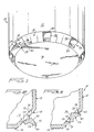
- Figure 1 is a bottom perspective view of the plunger of the invention illustrating several of the multiple vents formed therein; for purposes of illustration only, one has been shown as open and the others as closed;
- Figure 2 is a cross-sectional detail through the plunger with a valve flap in its open position;
- Figure 3 is a cross-sectional detail similar to figure 2 with the valve flap closed;
- Figure 4 is a cross-sectional detail through a cartridge as the plunger is advanced to exhaust the air; and
- Figure 5 is a cross-sectional view similar to figure 4 with the plunger contacting the dispensing material and the valve flaps closed in reaction to contact therewith.
-
- Referring now more specifically to the drawings, the plunger 10 of the invention, preferably formed as a unitary member of an appropriate synthetic resinous material, includes a
cylindrical body wall 12 adapted to slidably engage and provide an effective seal with the interior surface of acartridge body 14. - The plunger further includes a leading face or
end panel 16 of a diameter less than that defined by theplunger wall 12 and integrally joined to the lower edge of thewall 12 by an annularconical section 18. Thepanel 16 can be of any appropriate configuration in accord with thematerial 20 to be dispensed and the nature of the plunger positioning means and pusher assembly used to forwardly drive the plunger and expel the material. - As the plunger 10 is initially inserted into a filled cartridge, it is essential that trapped air between the
cartridge leading panel 16 and the material be properly and completely evacuated. Pursuant thereto, a series ofventing openings 22 are provided through theconical section 18 peripherally thereabout. While probably not particularly practical, one or two relatively large openings can be provided. However, multiple openings to equalize the air flow and minimize air pressure is much preferred. As one example, eight equallyspaced openings 22 can be provided, each extending along an arc of approximately 13°. The openings are generally rectangular or slightly trapezoidal with thelower edge 24, that edge closest to thebottom panel 16, being slightly shorter than theupper edge 26 immediately inward of the lower edge of thecylindrical wall 12. These edges as well as the opposed side edges are preferably inwardly undercut. - The
openings 22, and in particular the combined flow area defined bymultiple openings 22 provides for an effective expelling of the trapped air as suggested in figure 4 wherein air movement is defined by the direction arrows. However, upon engagement of the plunger 10 with thematerial 20 to be dispensed, it is essential that the openings be closed. Pursuant thereto, eachopening 22 is provided with avalve flap 28 integrally formed with theconical section 18 by aliving hinge 30 along and coextensive with thelower edge 24 of the opening 22. Each valve flap 28 in its at rest position, that is under insufficient external pressure to move to a sealed position relative to thecorresponding opening 22, extends downwardly and outwardly relative to thecorresponding opening 22 to allow for the desired free flowing air discharge. It is only upon a complete evacuation of the air and an engagement of the valve flaps with thematerial 20 to be dispensed, and the greater viscosity thereof, that sufficient pressure is exerted on the valve flaps to move these flaps to closed positions within theopenings 22, thus preventing discharge of thematerial 20 and an air-tight seal of the material within thecartridge tube 14. - Noting the details of the
valve flaps 28, it will be seen that theseflaps 28, in the open position thereof, are inwardly offset from the outer face of theplunger side wall 12 so as to avoid any interference with the inner surface of thecartridge tube 14 or with the sealing of the side wall to this inner surface as the plunger moves therein. - In order to provide a highly effective sealing of each of the
openings 22, thevalve flaps 28 are of a wedge-shaped configuration having an outer face slightly larger than the openings, an inwardly directed body defined by upper and lower angled ortapered faces side faces 38 which engage, in the manner of a wedge, with the edges of thecorresponding opening 22 in a progressively tighter and more effective sealing manner as the valve flaps move to a fully seated position within the openings. Noting figure 3 in particular, it will be seen that inward movement of each valve flap is limited, with the fully seated position of the flap being defined by alip portion 40 along the free edge of thevalve flap 28 remote from theliving hinge 30. Thislip portion 40 extends beyond the uppertapered face 34 to define a retainingshoulder 42 and, as illustrated, will overlie theconical section 18 immediately above theopening 22. With the valve flaps fully seated, the cartridge tube is effectively sealed with the initially entrapped air removed and the dispensing material effectively isolated from ambient air. - From the foregoing, it will be appreciate that the plunger of the invention is unique in its ability to provide for an effective evacuation of entrapped air and a subsequent air-tight sealing of the cartridge contents in a simple but highly distinctive manner, neither utilizing nor requiring any means external to the unitary molded plunger structure itself.
- The foregoing is considered illustrative of the features of the invention, and obvious variations thereof as may occur to one skilled in the art, as for example in the specific configuration of the openings and valve flaps, are to be considered within the scope of the claims following hereinafter.
Claims (9)
- An air-venting plunger (10) for a dispensing tube for viscous materials, said plunger (10) comprising a leading face (16) and a peripheral wall (12) extending rearward from said leading face (16) for a plunger-guiding engagement within a dispensing tube (14) with said leading face forwardly directed for selected movement into dispensing engagement with a tube-contained viscous material, air venting means (22) in said plunger for unencumbered air flow rearwardly through said plunger (10) relative to said leading face (16) upon forward movement of said plunger (10), characterized in that said plunger (10) further comprises valve means (28) adjacent said venting means (22) for closing said venting means, and means (30) both for retaining said valve means in an open position remote from said venting means (22) for allowing air flow through said venting means (22), and for allowing movement of said valve means (28) to a closed position closing said venting means upon encountering a material of greater resistance to flow than air.
- An air-venting plunger as in claim 1 wherein said venting means (22) comprises at least one opening through said plunger (10), said valve means (28) comprising a valve flap associated with said at least one opening.
- The air-venting plunger of claim 1 or 2, wherein said means (30) both for retaining said valve means (28) in an open position and allowing movement of said valve means (28) to a closed position comprising a living hinge (30) integrally joining said valve flap to said plunger and having an inherent memory retaining said valve flap in said open position while allowing for selected movement of said valve flap to said closed position in accord with resistance encountered to forward movement of said plunger.
- A self-venting plunger (10) for use in the dispensing of viscous material (20) contained within a dispensing tube, said plunger (10) comprising a leading face (16), a peripheral wall (12) integral with and extending rearward from said leading face (16), air venting means (22) defining an air path through said plunger (10) for free discharge of air therethrough as said plunger is moved inwardly within a dispensing tube (14) toward contained viscous material, characterized in that said air venting means (22) comprises at least one vent opening (22) defined through said plunger forward of said peripheral wall and a valve flap (28) mounted on said plunger (10) and movable between a forward open position remote from said at least one opening (22) for free flow of air thereby and through said at least one opening (22), said valve flap (28) being selectively movable to a second closed position closing said at least one opening (22) upon encountering resistance to inward movement of said plunger (10) greater than that of an air flow thereby.
- The self-venting plunger of claim 4 wherein said valve flap (28) is integral with said plunger (10) with a living hinge (30) defined therebetween, said living hinge (30) having an inherent memory retaining said valve flap (28) remote from said opening (22) until encountering a predetermined resistance to forward movement of said plunger.
- The air or self-venting plunger of anyone of claims 2 to 5 wherein said plunger (10) includes a conical section (18) integrally defined between said leading face (16) and said peripheral wall (12), said at least one opening of said venting means (22) and said valve flap (28) being formed within said conical section (18) rearward of said leading face (16) and within peripheral confines defined by said peripheral wall (12).
- The air or self-venting plunger of anyone of claims 2 to 6 wherein said plunger (10) comprises multiple duplicate openings at peripherally spaced points about said conical section (18), each of said openings (22) having a valve flap (28) associated therewith and duplicating said first mentioned valve flap.
- The air or self-venting plunger of anyone of claims 2 to 7 wherein each valve flap (28) has a wedge-shaped face thereon forcibly received and progressively sealing within the associated opening upon movement of said valve flap to said closed position.
- The air or self-venting plunger of anyone of claims 2 to 8 including lip means (40) on each of said valve flaps (28) limiting inward movement thereof in an associated opening.
Applications Claiming Priority (2)
| Application Number | Priority Date | Filing Date | Title |
|---|---|---|---|
| US890412 | 1997-07-09 | ||
| US08/890,412 US5878922A (en) | 1997-07-09 | 1997-07-09 | Self venting plunger |
Publications (3)
| Publication Number | Publication Date |
|---|---|
| EP0900599A2 EP0900599A2 (en) | 1999-03-10 |
| EP0900599A3 EP0900599A3 (en) | 1999-08-25 |
| EP0900599B1 true EP0900599B1 (en) | 2002-10-23 |
Family
ID=25396641
Family Applications (1)
| Application Number | Title | Priority Date | Filing Date |
|---|---|---|---|
| EP98401726A Expired - Lifetime EP0900599B1 (en) | 1997-07-09 | 1998-07-08 | Self venting plunger |
Country Status (9)
| Country | Link |
|---|---|
| US (1) | US5878922A (en) |
| EP (1) | EP0900599B1 (en) |
| JP (1) | JPH1191840A (en) |
| CN (1) | CN1101774C (en) |
| BR (1) | BR9802394A (en) |
| CA (1) | CA2241731A1 (en) |
| DE (1) | DE69808865T2 (en) |
| ID (1) | ID21560A (en) |
| TW (1) | TW411384B (en) |
Families Citing this family (29)
| Publication number | Priority date | Publication date | Assignee | Title |
|---|---|---|---|---|
| DE69637826D1 (en) * | 1996-02-02 | 2009-03-12 | Osaka Shipbuilding | METHOD FOR MANUFACTURING A DOUBLE AEROSOL VESSEL, AND THIS CONTAINER |
| JP3626367B2 (en) * | 1999-05-07 | 2005-03-09 | 武蔵エンジニアリング株式会社 | Plunger for syringe of liquid dispenser |
| ATE263092T1 (en) * | 2000-01-11 | 2004-04-15 | Stebler & Co Ag | PISTON FOR CLOSING A CARTRIDGE |
| DE20117778U1 (en) * | 2001-10-31 | 2003-03-20 | Sulzer Chemtech Ag, Winterthur | Cartridge piston with ventilation |
| EP1441971A4 (en) * | 2001-11-05 | 2007-11-21 | Sonoco Dev Inc | Self-venting ink cartridge |
| KR100841623B1 (en) * | 2002-03-21 | 2008-06-27 | 엘지디스플레이 주식회사 | Polishing device for liquid crystal panel |
| US6712245B2 (en) * | 2002-07-15 | 2004-03-30 | Arther Barrett | Venting plunger for caulk cartridges |
| US20050072750A1 (en) * | 2003-10-03 | 2005-04-07 | Steadman Greg Allen | Spillproof and shotgun release container |
| US7771514B1 (en) * | 2004-02-03 | 2010-08-10 | Airgard, Inc. | Apparatus and method for providing heated effluent gases to a scrubber |
| US7697827B2 (en) | 2005-10-17 | 2010-04-13 | Konicek Jeffrey C | User-friendlier interfaces for a camera |
| US7611684B2 (en) * | 2006-08-09 | 2009-11-03 | Airgard, Inc. | Effluent gas scrubber and method of scrubbing effluent gasses |
| WO2009036963A2 (en) * | 2007-09-19 | 2009-03-26 | Kettenbach Gmbh & Co. Kg | Container |
| GB0721774D0 (en) * | 2007-11-07 | 2007-12-19 | 3M Innovative Properties Co | one-piece vented piston |
| US7854792B2 (en) * | 2008-09-17 | 2010-12-21 | Airgard, Inc. | Reactive gas control |
| US20100237094A1 (en) * | 2009-03-18 | 2010-09-23 | Benjamin Ii Wilken | Plunger apparatus for emptying a cartridge using paint stir stick |
| EP2461912B1 (en) | 2009-08-04 | 2016-08-17 | 3M Innovative Properties Company | Dispensing device with pressure release |
| USD658763S1 (en) | 2010-02-02 | 2012-05-01 | 3M Innovative Properties Company | Dental capsule |
| US8568446B2 (en) * | 2010-05-13 | 2013-10-29 | Ethicon Endo-Surgery, Inc. | Multi-chamber therapeutic cell applicator instrument |
| GB201011143D0 (en) | 2010-07-01 | 2010-08-18 | Rieke Corp | Dispensers |
| GB201212042D0 (en) * | 2012-07-05 | 2012-08-22 | Rieke Corp | Pump dispensers |
| US9469061B2 (en) | 2013-01-30 | 2016-10-18 | Plas-Pak Industries Inc | One-piece ventable piston for a dispensing apparatus, a dispensing apparatus with same, and method of making same |
| EP2987560A1 (en) * | 2014-08-21 | 2016-02-24 | Sulzer Mixpac AG | Apparatus for dispensing a medium and method for front filing the apparatus |
| JP5651803B1 (en) * | 2014-08-25 | 2015-01-14 | 加賀ワークス株式会社 | Plunger for pneumatic dispenser |
| JP5993077B1 (en) * | 2015-10-19 | 2016-09-14 | 加賀ワークス株式会社 | Viscous material dispenser cartridge |
| IT201600080003A1 (en) * | 2016-07-29 | 2018-01-29 | Dropsa Spa | Pump equipped with a lubricant containment tank |
| US12070768B2 (en) | 2017-12-20 | 2024-08-27 | Medmix Switzerland Ag | Piston, cartridge and method of venting a cartridge |
| US11154887B2 (en) * | 2017-12-20 | 2021-10-26 | Sulzer Mixpac Ag | Piston, cartridge and method of venting a cartridge |
| CN108554726A (en) * | 2018-06-25 | 2018-09-21 | 江苏瑞合硕电子科技有限公司 | The antidrip vacuum glue of two-component fills machine |
| CN113623164A (en) * | 2021-09-06 | 2021-11-09 | 德帕姆(杭州)泵业科技有限公司 | Environment-friendly metering pump and control device thereof |
Family Cites Families (12)
| Publication number | Priority date | Publication date | Assignee | Title |
|---|---|---|---|---|
| US2755003A (en) * | 1954-11-26 | 1956-07-17 | William A Sherbondy | Dispensing device for plastic materials and the like |
| DE3615659A1 (en) * | 1986-05-09 | 1987-11-12 | Hilti Ag | PRESSURE PISTON WITH STORAGE CHAMBER |
| US4819836A (en) * | 1987-06-10 | 1989-04-11 | Mega Plast Product- U. Verpackungsentwicklung Marketing Gesellschaft Mit Beschrankter Haftung & Co. | Dispenser for dispensing paste compositions |
| DE3723309A1 (en) * | 1987-07-15 | 1989-01-26 | Fischbach A Kunststoff Kg | MIXING DEVICE |
| DE58903082D1 (en) * | 1988-06-03 | 1993-02-04 | Wilhelm A Keller | DISCHARGE CARTRIDGE WITH STORAGE CYLINDER AND PISTON PISTON. |
| IT1217852B (en) * | 1988-06-17 | 1990-03-30 | Guala Spa | DISPENSER OF PASTOUS PRODUCTS, PARTICULARLY OF PASTA TOOTHPASTE |
| CN2058166U (en) * | 1989-08-28 | 1990-06-13 | 施锡山 | Bottle cover with one-way valve |
| CA2027786C (en) * | 1989-10-31 | 1997-01-28 | Koichi Sugita | Combination container and pump |
| DE59103399D1 (en) * | 1990-06-21 | 1994-12-08 | Wilhelm A Keller | Discharge cartridge with storage cylinder and delivery piston. |
| EP0497739B1 (en) * | 1991-01-29 | 1996-10-09 | Wilhelm A. Keller | Dispensing cartridge with a supply cylinder and an expulsion piston |
| DE9110529U1 (en) * | 1991-08-26 | 1991-10-10 | Prestele, Eugen, 8900 Augsburg | cartridge |
| IT1256628B (en) * | 1992-12-04 | 1995-12-12 | DISPENSER OF FLUID SUBSTANCES, WITH DEFORMABLE HEAD |
-
1997
- 1997-07-09 US US08/890,412 patent/US5878922A/en not_active Expired - Lifetime
-
1998
- 1998-06-25 CA CA002241731A patent/CA2241731A1/en not_active Abandoned
- 1998-07-02 TW TW087110747A patent/TW411384B/en not_active IP Right Cessation
- 1998-07-02 JP JP10187615A patent/JPH1191840A/en not_active Ceased
- 1998-07-06 BR BR9802394A patent/BR9802394A/en not_active IP Right Cessation
- 1998-07-08 EP EP98401726A patent/EP0900599B1/en not_active Expired - Lifetime
- 1998-07-08 DE DE69808865T patent/DE69808865T2/en not_active Expired - Lifetime
- 1998-07-09 CN CN98115490A patent/CN1101774C/en not_active Expired - Fee Related
- 1998-07-09 ID IDP980967A patent/ID21560A/en unknown
Also Published As
| Publication number | Publication date |
|---|---|
| CN1204607A (en) | 1999-01-13 |
| EP0900599A3 (en) | 1999-08-25 |
| CA2241731A1 (en) | 1999-01-09 |
| TW411384B (en) | 2000-11-11 |
| JPH1191840A (en) | 1999-04-06 |
| US5878922A (en) | 1999-03-09 |
| DE69808865D1 (en) | 2002-11-28 |
| BR9802394A (en) | 1999-06-15 |
| CN1101774C (en) | 2003-02-19 |
| ID21560A (en) | 1999-06-24 |
| EP0900599A2 (en) | 1999-03-10 |
| DE69808865T2 (en) | 2003-06-18 |
Similar Documents
| Publication | Publication Date | Title |
|---|---|---|
| EP0900599B1 (en) | Self venting plunger | |
| US4869403A (en) | Cartridge for pasty materials | |
| AU668173B2 (en) | Sealant cartridge | |
| US7506783B2 (en) | Dual fluid cartridge assembly | |
| US4632672A (en) | Self venting syringe plunger | |
| EP0592741B1 (en) | Sausage dispensing adapter | |
| US5316186A (en) | Fully dischargeable cartridge for paste-like substances | |
| EP1945559B1 (en) | Plunger and plunger assembly for a cartridge, system for storing a substance, and method of filling and sealing a substance in a delivery system | |
| EP0351517B1 (en) | A dispenser of paste products, in particular toothpaste | |
| JPH0631112B2 (en) | Discharge cartridge with storage cylinder and transfer piston | |
| US5560521A (en) | Recyclable caulk cartridge with breakaway nozzle | |
| US7014079B2 (en) | Caulking tube replacement tip | |
| EP0426408B1 (en) | Combined container and pump | |
| US4522316A (en) | Container for plastic substances | |
| JP2005082246A (en) | Cartridge with a bleedable piston | |
| CA2248696C (en) | Industrial syringe | |
| NL8100169A (en) | BOTTOM SEAL FOR A HOLLOW CYLINDRICAL STRING HOLDER. | |
| EP1897463B1 (en) | Venting system for a product dispensing device | |
| EP0575729B1 (en) | Dispensing apparatus for pasty substances | |
| US20030120220A1 (en) | Self-venting movable seal and plunger | |
| WO1995029853A1 (en) | Cartridge dispenser with interior bag and interlocking lid | |
| KR19990008176A (en) | Cartridges and Cartridge Systems | |
| EP0628354B1 (en) | Sealing plug | |
| WO2024105636A1 (en) | Liquid dispensing apparatus | |
| WO2023111883A1 (en) | Dispensing portions of viscous food products |
Legal Events
| Date | Code | Title | Description |
|---|---|---|---|
| PUAI | Public reference made under article 153(3) epc to a published international application that has entered the european phase |
Free format text: ORIGINAL CODE: 0009012 |
|
| AK | Designated contracting states |
Kind code of ref document: A2 Designated state(s): BE CH DE FI FR GB IT LI NL |
|
| AX | Request for extension of the european patent |
Free format text: AL;LT;LV;MK;RO;SI |
|
| PUAL | Search report despatched |
Free format text: ORIGINAL CODE: 0009013 |
|
| AK | Designated contracting states |
Kind code of ref document: A3 Designated state(s): AT BE CH CY DE DK ES FI FR GB GR IE IT LI LU MC NL PT SE |
|
| AX | Request for extension of the european patent |
Free format text: AL;LT;LV;MK;RO;SI |
|
| RIC1 | Information provided on ipc code assigned before grant |
Free format text: 6B 05C 17/01 A, 6B 05C 17/005 B |
|
| 17P | Request for examination filed |
Effective date: 20000216 |
|
| AKX | Designation fees paid |
Free format text: BE CH DE FI FR GB IT LI NL |
|
| 17Q | First examination report despatched |
Effective date: 20010215 |
|
| GRAG | Despatch of communication of intention to grant |
Free format text: ORIGINAL CODE: EPIDOS AGRA |
|
| GRAG | Despatch of communication of intention to grant |
Free format text: ORIGINAL CODE: EPIDOS AGRA |
|
| GRAG | Despatch of communication of intention to grant |
Free format text: ORIGINAL CODE: EPIDOS AGRA |
|
| GRAH | Despatch of communication of intention to grant a patent |
Free format text: ORIGINAL CODE: EPIDOS IGRA |
|
| GRAH | Despatch of communication of intention to grant a patent |
Free format text: ORIGINAL CODE: EPIDOS IGRA |
|
| GRAA | (expected) grant |
Free format text: ORIGINAL CODE: 0009210 |
|
| AK | Designated contracting states |
Kind code of ref document: B1 Designated state(s): BE CH DE FI FR GB IT LI NL |
|
| REG | Reference to a national code |
Ref country code: GB Ref legal event code: FG4D |
|
| REG | Reference to a national code |
Ref country code: CH Ref legal event code: EP |
|
| REF | Corresponds to: |
Ref document number: 69808865 Country of ref document: DE Date of ref document: 20021128 |
|
| REG | Reference to a national code |
Ref country code: CH Ref legal event code: NV Representative=s name: KIRKER & CIE SA |
|
| ET | Fr: translation filed | ||
| PG25 | Lapsed in a contracting state [announced via postgrant information from national office to epo] |
Ref country code: FI Free format text: LAPSE BECAUSE OF NON-PAYMENT OF DUE FEES Effective date: 20030708 |
|
| PG25 | Lapsed in a contracting state [announced via postgrant information from national office to epo] |
Ref country code: LI Free format text: LAPSE BECAUSE OF NON-PAYMENT OF DUE FEES Effective date: 20030731 Ref country code: CH Free format text: LAPSE BECAUSE OF NON-PAYMENT OF DUE FEES Effective date: 20030731 |
|
| PLBE | No opposition filed within time limit |
Free format text: ORIGINAL CODE: 0009261 |
|
| STAA | Information on the status of an ep patent application or granted ep patent |
Free format text: STATUS: NO OPPOSITION FILED WITHIN TIME LIMIT |
|
| 26N | No opposition filed |
Effective date: 20030724 |
|
| PG25 | Lapsed in a contracting state [announced via postgrant information from national office to epo] |
Ref country code: NL Free format text: LAPSE BECAUSE OF NON-PAYMENT OF DUE FEES Effective date: 20040201 |
|
| REG | Reference to a national code |
Ref country code: CH Ref legal event code: PL |
|
| NLV4 | Nl: lapsed or anulled due to non-payment of the annual fee |
Effective date: 20040201 |
|
| PG25 | Lapsed in a contracting state [announced via postgrant information from national office to epo] |
Ref country code: IT Free format text: LAPSE BECAUSE OF NON-PAYMENT OF DUE FEES Effective date: 20050708 |
|
| PGFP | Annual fee paid to national office [announced via postgrant information from national office to epo] |
Ref country code: BE Payment date: 20070710 Year of fee payment: 10 |
|
| PG25 | Lapsed in a contracting state [announced via postgrant information from national office to epo] |
Ref country code: BE Free format text: LAPSE BECAUSE OF NON-PAYMENT OF DUE FEES Effective date: 20080731 |
|
| PGFP | Annual fee paid to national office [announced via postgrant information from national office to epo] |
Ref country code: FR Payment date: 20110727 Year of fee payment: 14 |
|
| PGFP | Annual fee paid to national office [announced via postgrant information from national office to epo] |
Ref country code: DE Payment date: 20110706 Year of fee payment: 14 Ref country code: GB Payment date: 20110706 Year of fee payment: 14 |
|
| GBPC | Gb: european patent ceased through non-payment of renewal fee |
Effective date: 20120708 |
|
| REG | Reference to a national code |
Ref country code: FR Ref legal event code: ST Effective date: 20130329 |
|
| PG25 | Lapsed in a contracting state [announced via postgrant information from national office to epo] |
Ref country code: GB Free format text: LAPSE BECAUSE OF NON-PAYMENT OF DUE FEES Effective date: 20120708 Ref country code: DE Free format text: LAPSE BECAUSE OF NON-PAYMENT OF DUE FEES Effective date: 20130201 Ref country code: FR Free format text: LAPSE BECAUSE OF NON-PAYMENT OF DUE FEES Effective date: 20120731 |
|
| REG | Reference to a national code |
Ref country code: DE Ref legal event code: R119 Ref document number: 69808865 Country of ref document: DE Effective date: 20130201 |