EP0900289B1 - Anordnung zum verschliessen eines geschlossenen produktionssytem - Google Patents
Anordnung zum verschliessen eines geschlossenen produktionssytem Download PDFInfo
- Publication number
- EP0900289B1 EP0900289B1 EP97921427A EP97921427A EP0900289B1 EP 0900289 B1 EP0900289 B1 EP 0900289B1 EP 97921427 A EP97921427 A EP 97921427A EP 97921427 A EP97921427 A EP 97921427A EP 0900289 B1 EP0900289 B1 EP 0900289B1
- Authority
- EP
- European Patent Office
- Prior art keywords
- portal
- spinpack
- channel
- equipment
- skirt
- Prior art date
- Legal status (The legal status is an assumption and is not a legal conclusion. Google has not performed a legal analysis and makes no representation as to the accuracy of the status listed.)
- Expired - Lifetime
Links
Images




Classifications
-
- D—TEXTILES; PAPER
- D01—NATURAL OR MAN-MADE THREADS OR FIBRES; SPINNING
- D01D—MECHANICAL METHODS OR APPARATUS IN THE MANUFACTURE OF ARTIFICIAL FILAMENTS, THREADS, FIBRES, BRISTLES OR RIBBONS
- D01D5/00—Formation of filaments, threads, or the like
- D01D5/11—Flash-spinning
-
- Y—GENERAL TAGGING OF NEW TECHNOLOGICAL DEVELOPMENTS; GENERAL TAGGING OF CROSS-SECTIONAL TECHNOLOGIES SPANNING OVER SEVERAL SECTIONS OF THE IPC; TECHNICAL SUBJECTS COVERED BY FORMER USPC CROSS-REFERENCE ART COLLECTIONS [XRACs] AND DIGESTS
- Y10—TECHNICAL SUBJECTS COVERED BY FORMER USPC
- Y10T—TECHNICAL SUBJECTS COVERED BY FORMER US CLASSIFICATION
- Y10T29/00—Metal working
- Y10T29/49—Method of mechanical manufacture
- Y10T29/49718—Repairing
- Y10T29/49721—Repairing with disassembling
-
- Y—GENERAL TAGGING OF NEW TECHNOLOGICAL DEVELOPMENTS; GENERAL TAGGING OF CROSS-SECTIONAL TECHNOLOGIES SPANNING OVER SEVERAL SECTIONS OF THE IPC; TECHNICAL SUBJECTS COVERED BY FORMER USPC CROSS-REFERENCE ART COLLECTIONS [XRACs] AND DIGESTS
- Y10—TECHNICAL SUBJECTS COVERED BY FORMER USPC
- Y10T—TECHNICAL SUBJECTS COVERED BY FORMER US CLASSIFICATION
- Y10T29/00—Metal working
- Y10T29/49—Method of mechanical manufacture
- Y10T29/49718—Repairing
- Y10T29/49721—Repairing with disassembling
- Y10T29/4973—Replacing of defective part
-
- Y—GENERAL TAGGING OF NEW TECHNOLOGICAL DEVELOPMENTS; GENERAL TAGGING OF CROSS-SECTIONAL TECHNOLOGIES SPANNING OVER SEVERAL SECTIONS OF THE IPC; TECHNICAL SUBJECTS COVERED BY FORMER USPC CROSS-REFERENCE ART COLLECTIONS [XRACs] AND DIGESTS
- Y10—TECHNICAL SUBJECTS COVERED BY FORMER USPC
- Y10T—TECHNICAL SUBJECTS COVERED BY FORMER US CLASSIFICATION
- Y10T29/00—Metal working
- Y10T29/53—Means to assemble or disassemble
- Y10T29/53096—Means to assemble or disassemble including means to provide a controlled environment
Definitions
- This invention relates to seals and sealing arrangements and especially to seals and sealing arrangements for near atmospheric, closed production chambers.
- a sealing system which comprises a channel with a liquid and skirt arrangement is diclosed in Patent Abstracts of Japan, vol. 012, no. 070 (C-479).
- a spin solution is carried from a solutioning system to a plurality of spinpacks in a spin cell.
- a spinpack becomes fouled during the manufacturing process and needs to be shut down and replaced.
- the manufacturing process has been engineered such that production can continue while a single spinpack is not operating, the spinpack is positioned within a spin cell that is closed to prevent or minimize the release of the spin agent.
- the spin solution is a combination of olefin polymer and a CFC spin agent and access to the spinpack is provided from above the spin cell with a number of precautions and procedures to minimize the release of vaporized CFC spin agent which is substantially heavier than air.
- E. I. du Pont de Nemours and Company DuPont
- pentane will be used as the spin agent and thus many changes to the process are necessary in light of the flammability of pentane that did not exist with the CFC spin agent.
- One consideration is that access by human personnel to the spin cell for changing spinpacks will be more limited.
- a remotely operated connector offered in the Grayloc® product catalog by Gray Tool Company (a subsidiary of Combustion Engineering) shows a system for connecting two pipe ends with specially designed mating surfaces.
- the system has a clamping mechanism with two pivoting clamps each having an arcuate, wedge shaped surface that pivots toward one another to engage a corresponding surface on the pipe flange.
- the two pipe flanges must first be aligned so that the two pipes are generally coaxial. Then the pipes are brought together axially so that the wedge surfaces on the pipe flange may pass between the pivoting clamps and engage a conical seal. This arrangement would not accommodate a lateral entry of the pipe.
- lateral entry or “lateral approach” are each intended to mean an arrangement where the end of one pipe is brought to the end of another pipe for the purposes of making a connection between the two pipes such that the approach of the one pipe is from a direction which is lateral with respect to the axes of the two pipes.
- the two pipes In the perfect sense of "lateral entry", the two pipes have parallel axes and the direction of approach is perpendicular to the axes of each of the pipes.
- the pertinent portion of the pipes at which to consider the axis of each pipe is at the end that is to be connected to the other pipe.
- one pipe need not be fixed or stationary, but that both pipes may be in motion toward a position for connection and such direction of motion need not be primarily in the lateral direction. It is the relative motion of the pipes to one another that provides for lateral approach.
- a process which includes providing the equipment into the chamber through a portal wherein the portal and equipment includes a sealing system which includes a skirt and a circumscribing channel arranged entirely around the portal with a liquid therein and wherein the skirt projects into the liquid in the channel so that the cover and skirt close and seal the portal and the chamber.
- the portal is closed with a gate from within the chamber isolating the equipment from the interior of the chamber and the equipment is removed from the portal such that the skirt comes out of the channel.
- the replacement equipment is installed into the portal such that the replacement equipment forms a similar seal as the replaced equipment and the gate is opened within the chamber to the portal so that the equipment is open to the interior of the chamber.
- a sealing system including a channel formed of a generally vertically upright inner wall arranged to approximately circumscribe the opening in the chamber, a generally concentric outer wall spaced from the periphery of said inner wall and a closed bottom between said inner and outer wall.
- a liquid sealing agent fills a substantial portion of the channel and a skirt is arranged to fit into the channel to close the space around the opening in the chamber.
- the channel is attached either the chamber or the equipment and the skirt is attached to the other such that as the equipment is brought into the opening, the skirt and the channel form a seal to close the opening around the equipment.
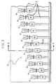
- FIG. 1 there is shown a closed spin cell, generally indicated by the number 12, which is particularly suited for flash spinning fiber and laying it down in sheet form.
- the spin cell 12 is closed to maintain a generally constant spinning environment and also to contain the vaporized spin agent which, under the new technology, is a flammable hydrocarbon.
- the space immediately outside the spin cell 12, generally called the spin cell access area or space, is preferably readily accessible to operations and maintenance personnel.
- the spin cell access space preferably has ordinary atmospheric air provided by conventional industrial HVAC equipment to provide a safe and comfortable work environment. Thus, while there must be access between the spin cell 12 and the spin cell access space, the access must be controlled through a sealed arrangement to minimize the cross mixing of the two atmospheres.
- the flash spun sheet material is created within the spin cell 12 by flash spinning a fiber from a polymer solution at a number of spinpacks 20 and casting the fiber down onto a conveyor 15 to overlap in the form of a web or sheet approximately ten to twelve feet (3.05-3.66 m) in width.
- the polymer solution is provided to each spin pack 20 by a solution supply line 17 having a solution control valve 18.
- the polymer passes through a downleg conduit 23 in the spinpack 20 where it is spun into fiber.
- the web or sheet is carried out of the spin cell 12 through a suitable sealed exit (not shown).
- the fundamental operation of the spinpacks 20 is generally as described in other disclosures related to the manufacture of Tyvek® spun bonded olefin such as US Patent Nos.
- the spinpacks 20 routinely become fouled and must be shut down for replacement.
- the spinpacks 20 are thus designed for being removed from the spin cell 12 during operation which means that the switchout or replacement operation is performed while the spin cell 12 is maintained closed and sealed.
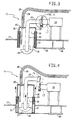
- the step wise process of removing a spinpack 20 and replacing it with a rebuilt or reconditioned spinpack is illustrated in Figures 3, 4 and 5. Beginning with Figure 3, a spinpack 20 is illustrated in its operational position with the spin head (not shown) and diffuser 21 extending into the main space in the spin cell 12 by projecting below the upper wall 13.
- the upper wall 13 includes a number of openings 14 therein at which the portals 30 are formed.
- Each portal 30 includes a peripheral wall 31 that surrounds the opening 14 and is sealed to the upper wall 13 by welding or other sealing arrangement such that each portal 30 forms an open ended (top and bottom) space that is roughly one meter by one meter by one meter.
- the peripheral wall 31 of the portal 30 is actually formed of a double wall or a pair of spaced concentric walls to form a deep and narrow open top seal channel 32 extending fully around the portal 30 like a moat.
- the spinpacks 20 each include a spinpack cover 25 and a spinpack skirt 26 projecting down from the periphery of the spinpack cover 25 to fit down into the seal channel 32.
- the spinpack skirt 26 preferably extends downwardly from the spinpack cover 25 about the depth of the seal channel 32.
- the weight of the spinpack 20 is preferably carried by the spinpack cover 25 on the top of the peripheral wall 31 although in an alternative arrangement, the spinpack skirt 26 may rest at the bottom of the seal channel 32 as shown in Figure 3.
- the seal channel 32 is substantially filled with water or other suitable liquid for forming a seal, in conjunction with the spinpack skirt 26 extending down into the seal channel 32, between the portal 30 and the spin cell access space.
- Each spinpack 20 is provided with numerous connections which, for purposes of clarity of the drawing figures, are not all shown.
- the connections are to provide fluids to the spinpack 20 for spinning, to electrically or otherwise provide data regarding operating conditions of the spinpack 20 and spin cell 12, and also to provide control signals to control and adjust the operation of the spinpack 20.
- polymer solution is provided through a number of solution supply lines 17, having a solution control valve 18 in each line, to each of the spinpacks 20.
- the connection of the spinpacks 20 to the solution supply lines 17 will be explained in detail below and preferably includes the feature of providing other fluids to the spinpack as will also be explained.
- the spinpacks 20 are each provided with purge gas, such as nitrogen, through a purge gas conduit 28 and a purge return conduit 29 for venting gases from the enclosed portal 30 to a flare or other suitable location.
- purge gas is provided while the spinpack 20 is in the transitional position as illustrated in Figure 4.
- the conduits 28 and 29 are connected through the spinpack cover 25.
- the conduits may alternatively be connected through the peripheral wall 31 below the seal channel 32, thus avoiding the need to connect and disconnect the same as a spinpack is being replaced.
- each spinpack 20 has now been described, the description will now move to the transitional position of the spinpack 20.
- the spinpack 20 has been shutdown and lifted up in the portal 30 to an intermediate or transitional position by a suitable lift or crane (not shown).
- Most of the connections, particularly the connection for the polymer solution have been separated or disconnected.
- the purge gas conduit 28 and purge return conduit 29 remain connected or the connection of the conduits 28 and 29 are connected at this stage.
- a slide gate 35 is moved into a position below the portal 30 to isolate the portal 30 from the main space in the spin cell 12.
- the slide gate 35 is arranged under the upper wall 13 of the spin cell 12 adjacent the base of the portal 30 for closing the bottom thereof.
- a slide gate drive 36 is arranged to move the slide gate back and forth along the bottom side of the upper wall 13 to clear the bottom of the portal 30 or to close and seal the base of the portal 30.
- the slide gate 35 is clear of the portal 30 so as to be in the open position allowing the spinpack 20 to be fully lowered into its operational position.
- the portal 30 is isolated from both the spin cell access space and the spin cell 12.
- the portal 30 Immediately after the slide gate 35 is closed, the portal 30 has an atmosphere which is essentially the same atmosphere as the spin cell 12. Such atmosphere comprises a significant concentration of the flammable hydrocarbon vapors from the spin agent. Thus, as noted above, it is important that the atmosphere in the portal 30 remains isolated from the spin cell access space.
- the spinpack skirt 26, while higher in the seal channel 32. is sized in conjunction with the size of the portal 30 and the size of the seal channel 32 so as to project below the surface of the water in the seal channel 32 and to maintain its seal while the spinpack 20 is in its transitional position.
- the transitional position is where the spinpack 20 is high enough in the portal to close the slide gate 35 (and the slide gate 35 is indeed closed) but not so high that the spinpack skirt 26 is out of the water in the seal channel 32.
- nitrogen or other inert gas is directed through a suitable valve into the purge gas conduit 28 to carry the atmosphere within the portal 30 through the purge return conduit 29, and suitable valving therefore, to purge the portal 30 of any flammable or other hazardous vapors or chemicals.
- the process of replacing a spinpack is essentially the reverse of the process for removing a spinpack 20.
- the replacement spinpack 20 is positioned over the portal 30 (with the cap 38 removed) and lowered until the lower extremity of the spinpack skirt 26 enters the water in the seal channel 32. In this position, the portal 30 will have an atmosphere from the spin cell access area which would include some oxygen content.
- the purge gas and purge return conduits 28 and 29 are reconnected so as to purge the portal 30 while the spinpack 20 is again in the transitional position as shown in Figure 4.
- the slide gate 35 is opened by the slide gate drive 36 and the spinpack 20 is lowered until the spinpack cover 25 rests on top of the peripheral wall 31 or in the alternative arrangement, the base of the spinpack skirt 26 rests at the bottom of the seal channel 32 and the connection between the spinpack 20 and the solution supply line 17 is aligned.
- the spinpack 20 is in its operational position, the remainder of the connections are made, other checks and inspections are completed, and then the spinpack 20 is put into operation in the operating spin cell 12.
- the seal channel 32 and spinpack skirt 26 will allow for some lateral and angular adjustment of the spinpack 20 relative to the spin cell 12; however, the spinpack 20 is moved almost exclusively in the vertical direction from the transitional position ( Figure 4) to the operational position ( Figure 3).
- the solution supply line 17 extends horizontally to the spinpack 20.
- pipe connections are known and available if the axis of the solution line were vertical so that the connection could be formed as the spinpack is lowered from the transitional position to the operational position.
- such an arrangement would require re-routing piping in a crowded space, plus add at least two additional bends in the piping.
- a simple and reliable coupling arrangement has been conceived and designed to provide the connection with a lateral entry or approach of the spinpack to the solution supply line 17 as desired.
- the coupling system is provided to connect the solution supply line 17 to the spinpack 20.
- the coupling system 50 is provided slightly above the portal 30 and away from where the technician would stand while installing or removing a spinpack 20.
- the area behind the portal 30 where the coupling system is located is rather unsuited for easy accessibility because of the piping, wiring and other equipment that is preferably located adjacent or connected with each spinpack 20.
- the coupling system 50 is preferably remotely operated.
- the coupling system 50 comprises a wear plate 60 which remains generally fixed adjacent the back side of the portal 30, and a pack flange 70 which is part of the spinpack 20.
- the wear plate 60 is attached to the end of the supply line 17 and, as seen in Figure 7, is generally planar and preferably machined smooth. In an alternative arrangement, the wearplate 60 could be attached directly to the solution valve 18, eliminating the section of solution supply line 17 shown between the valve 18 and the wearplate 60 in Figures 1 through 5.
- the wear plate 60 also includes several conduits extending therethrough. A solution conduit 61 is arranged in about the center of the wear plate 60 for carrying polymer solution into the spinpack 20.
- conduits 61, 62, 63 and 64 extend through the larger solution supply line 17; however, one or more of the conduits may alternatively be routed parallel to the solution supply line 17 to the wear plate 60 or may be supplied to the spinpack 20 through an entirely separate arrangement.
- the downleg conduit 23 acts as a mounting bracket and includes a pack flange 70 mounted at its distal end.
- the pack flange 70 includes passages which correspond to the conduits in the wear plate 60.
- the pack flange 70 includes a solution passage 71 in about the center thereof which corresponds to the solution conduit 61.
- a thermal fluid passage 72 which corresponds to the thermal fluid conduit 62.
- a thermal return passage 73 which generally corresponds with thermal return conduit 63.
- O-rings are provided about each of the passages to seal the connections between the respective passages in the pack flange 70 and conduits in the wear plate 60.
- a channel 74 which functions with the small orifice 64 as will be described below.
- O-rings 72a and 73a encircle the openings of the thermal fluid passage 72 and thermal fluid return passage 73, respectively.
- the coupling system 50 is arranged to form a connection between the spinpack 20 as it is lowered into its operational position adjacent the horizontally oriented solution supply line 17.
- the connection is formed by lateral entry or approach of the spinpack 20 with respect to the axes of both the solution passage 71 and the solution conduit 61.
- One apparent concern with trying to make such couplings, particularly in light of the desire to make the connection remotely, is to assure that the respective passages reliably become aligned with the respective conduits during the connection process. This is a particular concern when one understands that each of the spinpacks 20 is disassembled, cleaned up, parts replaced and reassembled after each use in the spin cell 12.
- the spinpack 20 As the spinpack 20 is reassembled, the downleg conduit 23 and the spinpack skirt 26 are each attached to the spinpack cover 25. Even with the best of efforts, it is unlikely that all the spinpacks 20 that may be used in all the various portals 30 will have the same precise arrangements between the spinpack skirt 26 and the pack flange 70. Moreover, one must appreciate that the spinpacks 20 and wear plates 60 will be subject to rough use both in the spin cell 12 and while being disassembled and rebuilt.
- the first order of business for the coupling system 50 to form the connection is to verify that the spinpack 20 is adequately aligned with the portal 30 and that the pack flange 70 is aligned with the wear plate 60.
- the spinpack 20 is normally centered above the portal 30 by a crane or other suitable equipment at the beginning of the installation process.
- a pin 78 is provided on the pack flange 70 to be received in a notch 68 in the wear plate 60.
- the notch 68 is preferably configured with a "V" shape with inclined “walls” or “ramps” at the opposite sides thereof to "catch" the pin and direct the pack flange 70 into the desired alignment with the wear plate 60 as the spinpack 20 is lowered into its operational position.
- the notch may also be described as having opposite walls splayed out from the bottom of the notch called the notchbottom.
- the non-mechanical seal between the spinpack skirt 26 and seal channel 32 is also suited to freely permit any necessary adjustments by the operator to correct the alignment in case the pin 78 is not quite falling into the notch 68.
- the notch 68 has an arcuate shape at the notchbottom, which is positioned to provide a relatively acceptable alignment of the pack flange 70 and the wear plate 60.
- a clearance is provided between the pin 78 and the notch 68, to allow the spinpack 20 to self-center, as required, when the coupling system clamp force is applied later.
- the sealing O-rings described above, are sufficiently large in diameter to properly seal the flange 70 to wear plate 60 anywhere within the clearance of the pin 78 to notch 68.
- the pin 78 also includes an oversized head 79 positioned at the distal end thereof.
- the wear plate 60 further includes a tapered back surface 69 forming a ramp at its upper portion. The tapered back surface 69 permits the oversize head 79 on the pin 78 to "catch" the wear plate 60 between the pack flange 70 and the head 79 to pull the pack flange 70 toward the wear plate 60, if the pack flange 70 is not close enough to contact the wear plate 60 on its own, as the spinpack is lowered into its operational position.
- the head 79 and tapered back surface 69 cooperate to position the pack flange 70 close to the wear plate 60.
- the wear plate 60 and the pack flange 70 are preferably arranged at a slight incline relative to the vertical.
- the incline is preferably in the range of about three degrees to about 15 degrees although such incline need not exist at all or could be more exaggerated.
- the purpose of the slight incline is to allow the pack flange 70 to contact the wear plate 60, on its own, and slide down in contact with it as the spinpack 20 is lowered into position. It is even conceivable that the pack flanges and wear plates could have a negative angle such as a slight incline where the pack flange 70 is angled slightly upwardly. Such modifications are within the scope of one having ordinary skill once such persons are provided with an explanation of the present invention.
- FIG 7 the coupling system 50 is illustrated with left and right clamps 80 and 90, respectively, wherein each is in its respective open position ready to receive the pack flange 70.
- the clamps 80 and 90 are carried by and hingedly secured to respective left and right clamp arms 81 and 91 by respective pins 82 and 92.
- the clamp arms 81 and 91 are themselves hinged at their upper ends to respective left and right upper lugs 83 and 93 of the wear plate 60 by left and right hinge pins 85 and 95.
- the clamp arms 81 and 91 pivot about the respective pins 85 and 95 to bring the clamps 80 and 90 toward and away from the center of the wear plate 60. Movement of the clamp arms 81 and 91 is effected by an actuator system generally indicated by the number 100.
- the actuator system 100 comprises a screw shaft 101 that includes two threaded portions 105 and 106 wherein the first threaded portion 105 has screw threads arranged in one direction and the second threaded portion 106 has screw threads arranged in the opposite direction.
- the first threaded portion 105 of the screw shaft 101 is associated with the left clamp arm 81 and the second threaded portion 106 of the screw shaft 101 is associated with the right clamp arm 91.
- Threaded onto the screw shaft 101 at the first threaded portion is a left threaded actuator pin 108.
- a right threaded actuator pin 109 is threaded onto the second threaded portion 106 of the screw shaft 101.
- the respective threaded actuator pins 108 and 109 are adapted so as to move along the screw shaft 101 in opposite directions as the screw shaft 101 is rotated about its axis with respect to the threaded actuator pins 108 and 109.
- the threaded actuator pins 108 and 109 are suitably connected to the lower portions of the respective left and right clamp arms 81 and 91 so as to rotate about the respective axes of the hinge pins 85 and 95.
- the clamp arms 81 and 91 have a yoke type configuration at the lower end thereof with the respective actuator pin passing transversely through the spaced pair of ears of the yoke and the screw shaft 101 passing through the opening of the yoke and a medial portion of the respective actuator pin.
- the left and right actuator pins 108 and 109 are arranged to extend through slides (not shown) in respective left and right lower lugs 88 and 98.
- a tie plate 111 is provided on the opposite ends of the actuator pins from the left and right lower lugs 88 and 98 having respective left and right slides 112 and 113.
- the clamps 80 and 90 are pivoted about respective hinge pins 85 and 95 toward and away from one another.
- the actuator system 100 is operated by rotation of the screw shaft 101 by a motor (not shown), a hand wheel (not shown) or other suitable device through a coupling 103 attached to a splined portion 102 at the end of the screw shaft 101.
- the splined connection of the coupling 103 and splined portion 102 allows the screw shaft 101 to move along its axis (laterally in Figure 7) which will provide advantages for the system 50 as will be explained below.
- the solution supply line 17 may be provided with suitable rigidity and strength to support the entire weight of a spinpack 20 under operational loads. However, it is preferred that the weight of the spinpacks 20 be supported by the spinpack cover 25 resting on the top edge of the peripheral wall 31.
- the peripheral wall 31 may include a flange to reinforce the top edge. Regardless of whether the coupling system 50 simply connects two pipes together or also provides the support for suspending the spinpack in position, the connection is preferably very tight. Thus, there would be zero or practically zero "play" between the wear plate 60 and the pack flange 70.
- the clamps 80 and 90 are provided with left and right bevelled jaws 89 and 99 which have a "V" shaped or bevelled configuration to squeeze the pack flange 70 to the wear plate 60 for a very firm or tight connection.
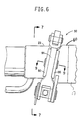
- the pack flange 70 includes left and right bevelled tabs 121 and 122 that engage left and right bevelled jaws 89 and 99, respectively (see Figure 8).
- the wear plate 60 similarly includes left and right bevelled tabs 125 and 126. As best seen in Figure 9, the tabs are configured with only one bevelled surface along the "back" side thereof while the "front" surfaces are flat or flush.
- the screw shaft 101 is provided with the limited freedom to move along its axis or in other words it is not fixed in a central position at the base of the wear plate 60.
- the clamps 80 and 90 also move in tandem with the screw shaft 101.
- This freedom of movement for the clamps 80 and 90 and the screw shaft 101 provides an additional measure of reliability for having a secure connection between the pack flange 70 and the wear plate 60.
- the coupling system 50 better accommodates irregularities of the spinpack 20 or the pack flange 70.
- the clamps 80 and 90 would have the freedom, while pulling hard together, to balance the forces on both sides of the wear plate 60 and pack flange 70.
- the clamp that comes into contact with the tabs would stop moving and the screw shaft 101 would simply move toward the stopped clamp because the screw shaft can slide on the splined portion 102 as it continues to rotate.
- the screw shaft 101 would be pulling the opposite clamp at double the normal rate because the screw shaft is moving both axially and rotationally. Once both clamps are in contact with the tabs, the forces on the tabs would increase at about the same rate.
- the small orifice 64 and the channel 74 Another feature of the present invention that has been briefly described is the small orifice 64 and the channel 74.
- the polymer solution is carried through the solution conduit 61 into the solution passage 71.
- This polymer solution is at relatively high pressure and temperature for spinning into fiber.
- it since it includes a flammable hydrocarbon, it is important that the connection between the pack flange 70 and the wear plate 60 be tight and the O-rings 71a and 71b keep the conduit and passage sealed. If one of the O-rings were to fail, it is preferred that the spinpack 20 be shut down.
- the channel 74 is positioned between the two concentric O-rings and the small orifice 64 is intended to be in fluid communication with the channel 74.
- Nitrogen or other inert gas, is provided to small orifice 64 through a valve including a pressure sensor to sense the pressure in the channel 74.
- the pressure of the nitrogen is preferably maintained at some middle pressure which is much less than the pressure of the polymer solution and higher than the pressure in the spin cell access space.
- the pressure sensor detects a change in the measured pressure, this would indicate that one of the O-rings has failed or is about to fail. More particularly, if the pressure goes up, one can deduce that the inner O-ring is about to fail because the high pressure solution is entering the channel 74.
- the inert gas may also be used to check the O-rings before the solution is allowed to pass from the solution valve 18 to the spinpack 20.
- nitrogen is pumped into the channel 74 through the small orifice 64 at a fairly high pressure and maintained at the high pressure for a predetermined test period. If there is no pressure drop, the O-rings are acceptable for starting up the spinpack. However, if the pressure drops, then it is presumed that there is at least some kind of problem with at least one of the O-ring seals and the connection 20 should be checked before it is put into operation. Equipment for measuring pressure drop are assumed to be sufficiently well known to those skilled in such arts that one is not needed to be illustrated for a full explanation of the invention.
Landscapes
- Engineering & Computer Science (AREA)
- Mechanical Engineering (AREA)
- Textile Engineering (AREA)
- Centrifugal Separators (AREA)
- Paints Or Removers (AREA)
- Ventilation (AREA)
- Spinning Methods And Devices For Manufacturing Artificial Fibers (AREA)
Claims (11)
- Verfahren zum Auswechseln von Ausrüstung (20) in einer im wesentlichen geschlossenen Kammer, wobei das Verfahren umfaßt:Einführen der Ausrüstung (20) in die Kammer durch einen Einlaß (30), wobei der Einlaß (30) und die Ausrüstung (20) ein Dichtungssystem aufweisen, das eine Schürze (26) und einen umschließenden Schacht (32) mit einer Flüssigkeit darin, der den gesamten Einlaß (30) umgibt, aufweist, und wobei die Schürze (26) in die Flüssigkeit in dem Schacht (32) reicht, so daß eine Abdeckung (25) und die Schürze (26) den Einlaß (30) und die Kammer abschließen und abdichten;Schließen des Einlasses (30) mit einer Absperrung (35) vom Inneren der Kammer aus, die die Ausrüstung (20) vom Inneren der Kammer isoliert;Herausheben der Ausrüstung (20) aus dem Einlaß (30), so daß die Schürze (26) aus dem Schacht (32) herauskommt;Installieren der Auswechselausrüstung (20) in den Einlaß (30), so daß die Auswechselausrüstung (20) eine ähnliche Abdichtung bildet wie die ausgewechselte Ausrüstung, so daß, wenn die Auswechselausrüstung in den Einlaß (30) installiert wird, die Schürze (26) in die Flüssigkeit in dem Schacht (32), der die Ausrüstung in den Einlaß (30) abdichtet, reicht; undÖffnen der Absperrung (35) innerhalb der Kammer zu dem Einlaß (30), so daß die Ausrüstung (20) für das Innere der Kammer zugänglich gemacht wird.
- Verfahren nach Anspruch 1, weiterhin beinhaltend den Schritt des Spülens des Raums zwischen der Abdeckung (25) und der Absperrung (35) mit inertem Gas, während der Raum innerhalb des Einlasses (30) von dem Inneren der Kammer und dem Außenraum abgeschlossen wird, bevor die Ausrüstung aus dem Einlaß (30) entnommen wird.
- Verfahren nach Anspruch 1 oder 2, weiterhin beinhaltend den Schritt des Spülens des Raums zwischen der Abdeckung (25) und Absperrung (35) mit inertem Gas, während der Raum innerhalb des Einlasses (30) von dem Inneren der Kammer und dem Außenraum abgeschlossen wird, bevor die Ausrüstung für das Innere der Kammer zugänglich gemacht wird.
- Verfahren nach Anspruch 1, 2 oder 3, weiterhin beinhaltend den Schritt des Anhebens der Ausrüstung (20) in dem Einlaß (30), während die Schürze (26) in der Flüssigkeit in dem Schacht (32) verbleibt, bevor der Schritt des Abschließens des Einlasses (30) mit der Absperrung (35) durchgeführt wird.
- Verfahren zum Auswechseln einer Spinnpackung (20) in einem Flash-Spinnsystem, wobei das Flash-Spinnen in einer im wesentlichen geschlossenen Spinnzelle (12) durchgeführt wird, und das Verfahren umfaßt:Einführen der Spinnpackung (20) in die Spinnzelle (12) durch einen Einlaß (30) hindurch, wobei der Einlaß (30) einen umschließenden Schacht (32) mit einer Flüssigkeit darin aufweist, der gänzlich um den Einlaß (30) herum angeordnet ist, und wobei die Spinnpackung (20) eine Abdeckung (25) und eine Schürze (26) aufweist, die von dieser ausgeht, um in die Flüssigkeit des Schachtes (32) zu reichen, so daß die Abdeckung (25) und die Schürze (26) den Einlaß (30) und die Spinnzelle (12) abschließen und abdichten;Anheben der Spinnpackung (20) zu einer Übergangsposition innerhalb des Einlasses (30), so daß die Schürze (26) in der Flüssigkeit verbleibt und die Abdichtung nicht unterbrochen wird;Schließen des Einlasses (30) mit der Absperrung (35) vom Inneren der Spinnzelle(12) aus, der die Spinnpackung (20) von dem Inneren der Spinnzelle (12) isoliert;Anheben der Spinnpackung (20) aus dem Einlaß (30), so daß die Schürze (26) aus dem Schacht (32) gezogen wird;Installieren einer Auswechselspinnpackung (20) in den Einlaß (30), so daß die Auswechselspinnpackung (20) eine Abdeckung (25) und eine Schürze (26) aufweist, und daß, wenn die Auswechselspinnpackung (20) in den Einlaß (30) installiert wird, die Schürze (26) in die Flüssigkeit in dem Schacht (32) reicht, wodurch die Spinnpackung (20) in den Einlaß (30) isoliert wird; undÖffnen der Absperrung (35) innerhalb der Spinnzelle (12) zu dem Einlaß, so daß die Spinnpackung (20) für das Innere der Spinnzelle (12) zugänglich ist.
- Verfahren nach Anspruch 5, weiterhin beinhaltend den Schritt des Spülens des Raums zwischen der Abdeckung (25) und der Absperrung (35) mit inertem Gas, während der Raum innerhalb des Einlasses (30) von dem Inneren der Spinnzelle (12) und Außenraum abgeschlossen wird, bevor die Spinnpackung (20) aus dem Einlaß (30) entnommen wird.
- Dichtungssystem zum Abdichten einer Kammer an einer Öffnung, an der Ausrüstung installiert wird, wobei die Ausrüstung bisweilen ausgewechselt werden muß, wobei die Dichtungsvorrichtung aufweist:ein erstes Dichtungselement, das ein Schacht (32) umfaßt, der aus einer im wesentlichen senkrechten inneren Wand, die so angeordnet ist, daß sie in etwa die Öffnung der Kammer umfaßt, einer im allgemeinen konzentrischen äußeren Wand, die einen Abstand von der Peripherie der Inneren Wand aufweist, und einem geschlossenen Boden zwischen der inneren und äußeren Wand gebildet ist;ein flüssiges Abdichtmittel, das einen erheblichen Teil des Schachtes ausfüllt; undein zweites Abdichtelement, das eine Schürze (26) aufweist, die so angeordnet ist, daß sie in den Schacht (32) des ersten Abdichtelements und in das flüssige Abdichtmittel paßt;wobei das erste oder das zweite Abdichtelement an der Kammer um die Öffnung angebracht ist und das andere der Abdichtelemente an der Ausrüstung angebracht ist, so daß die Schürze (26) und der Schacht (32) eine Abdichtung bilden, wenn die Ausrüstung in die Öffnung in der Kammer gebracht wird.
- Vorrichtung nach Anspruch 7, wobei das flüssige Abdichtmittel in dem Schacht Wasser ist.
- Vorrichtung nach Anspruch 7 oder 8, weiterhin beinhaltend eine Absperrung (35) zum Abschließen der Öffnung vom Inneren der Kammer aus.
- Vorrichtung nach Anspruch 7, 8 oder 9, wobei die Öffnung sich im oberen Teil der Kammer befindet und der Schacht (32) an der Kammer befestigt ist und die Schürze (26) an der Ausrüstung angebracht ist.
- Dichtungssystem zum Abdichten von Spinnpackungen (20) in einer Spinnzelle (12) bei einem Flash-Spinnvorgang, wobei das Dichtungssystem aufweist: einen Schacht (32) mit einem geschlossenen Boden, der eine Öffnung in der Spinnzelle (12) umgibt, um eine innere Wand und eine im wesentlichen konzentrische äußere Wand zu umfassen;ein flüssiges Abdichtmittel, das einen erheblichen Teil des Schachtes (32) ausfüllt; eine Abdeckung (25), die mit der Spinnpackung (20) verbunden ist und eine Schürze (26) aufweist, die sich von der Abdeckung (25) erstreckt, um in den Schacht (32) zu passen, und in die Flüssigkeit eintaucht; undeine Absperrung (35) zum Abschließen der Öffnung vom Inneren der Spinnzelle (12) aus.
Applications Claiming Priority (7)
| Application Number | Priority Date | Filing Date | Title |
|---|---|---|---|
| US1707396P | 1996-04-30 | 1996-04-30 | |
| US17073P | 1996-04-30 | ||
| US2727096P | 1996-09-27 | 1996-09-27 | |
| US27270P | 1996-09-27 | ||
| US08/847,941 US6101698A (en) | 1996-04-30 | 1997-04-21 | Arrangement for sealing a closed production system |
| PCT/US1997/007108 WO1997041282A1 (en) | 1996-04-30 | 1997-04-29 | Arrangement for sealing a closed production system |
| US847941 | 2001-05-02 |
Publications (2)
| Publication Number | Publication Date |
|---|---|
| EP0900289A1 EP0900289A1 (de) | 1999-03-10 |
| EP0900289B1 true EP0900289B1 (de) | 2000-10-11 |
Family
ID=27360699
Family Applications (1)
| Application Number | Title | Priority Date | Filing Date |
|---|---|---|---|
| EP97921427A Expired - Lifetime EP0900289B1 (de) | 1996-04-30 | 1997-04-29 | Anordnung zum verschliessen eines geschlossenen produktionssytem |
Country Status (8)
| Country | Link |
|---|---|
| US (2) | US6101698A (de) |
| EP (1) | EP0900289B1 (de) |
| JP (1) | JP2002515947A (de) |
| KR (1) | KR20000065104A (de) |
| CA (1) | CA2249565A1 (de) |
| DE (1) | DE69703289T2 (de) |
| ES (1) | ES2152091T3 (de) |
| WO (1) | WO1997041282A1 (de) |
Families Citing this family (5)
| Publication number | Priority date | Publication date | Assignee | Title |
|---|---|---|---|---|
| US6101698A (en) * | 1996-04-30 | 2000-08-15 | E. I. Du Pont De Nemours And Company | Arrangement for sealing a closed production system |
| US6634650B2 (en) * | 2001-11-16 | 2003-10-21 | Applied Materials, Inc. | Rotary vacuum-chuck with water-assisted labyrinth seal |
| US20030141611A1 (en) * | 2002-01-25 | 2003-07-31 | Giese Kenneth Charles | Adjustable shroud for spinning synthetic yarns |
| KR102178866B1 (ko) * | 2014-08-14 | 2020-11-13 | 세메스 주식회사 | 기판 처리 장치 및 방법 |
| CN118854465A (zh) * | 2024-06-27 | 2024-10-29 | 厦门当盛新材料有限公司 | 一种连接装置及闪蒸纺丝设备 |
Family Cites Families (17)
| Publication number | Priority date | Publication date | Assignee | Title |
|---|---|---|---|---|
| CH141840A (de) * | 1928-11-15 | 1930-08-31 | Kohorn Oscar & Co | Verfahren zur Reinigung der Düsen bei Kunstseidespinnmaschinen. |
| US2881013A (en) * | 1949-07-01 | 1959-04-07 | Us Electrical Motors Inc | Apparatus for sealing submersible devices |
| BE517791A (de) * | 1952-02-19 | |||
| US2954244A (en) * | 1956-08-10 | 1960-09-27 | Henry J Kaiser Company | Movable gas sealing device for furnaces and the like |
| US3757404A (en) * | 1970-11-25 | 1973-09-11 | Haefely & Cie Ag Emil | Process and means for replacement of components and/or operating media in encapsulated installations |
| US3851023A (en) * | 1972-11-02 | 1974-11-26 | Du Pont | Process for forming a web |
| US3860369A (en) | 1972-11-02 | 1975-01-14 | Du Pont | Apparatus for making non-woven fibrous sheet |
| JPS52155216A (en) * | 1976-06-18 | 1977-12-23 | Mitsubishi Rayon Co Ltd | Process and apparatus for dry spinning |
| NL168596C (nl) * | 1978-03-01 | 1982-04-16 | Neratoom | Afdichtende doorvoer voor een door een wand van een huis gevoerd, om een as roteerbaar lichaam. |
| US4286792A (en) * | 1980-03-10 | 1981-09-01 | United States Steel Corporation | Self-replenishing seal for the gas offtake piping of a coke oven and sealing method |
| JPS62210037A (ja) * | 1986-03-11 | 1987-09-16 | Kawasaki Steel Corp | ガス反応槽 |
| JP3130174B2 (ja) * | 1993-05-21 | 2001-01-31 | 富士写真フイルム株式会社 | レンズ付きフイルムユニットのフイルム装填装置 |
| US5320028A (en) * | 1993-10-01 | 1994-06-14 | Daniel Grunberg | Cooking utensil |
| IT1276034B1 (it) * | 1994-11-10 | 1997-10-24 | Barmag Barmer Maschf | Traversa di filatura per la filatura di una pluralita' di fili sintetici e procedimento per la sua produzione |
| US5618566A (en) * | 1995-04-26 | 1997-04-08 | Exxon Chemical Patents, Inc. | Modular meltblowing die |
| US5728219A (en) * | 1995-09-22 | 1998-03-17 | J&M Laboratories, Inc. | Modular die for applying adhesives |
| US6101698A (en) * | 1996-04-30 | 2000-08-15 | E. I. Du Pont De Nemours And Company | Arrangement for sealing a closed production system |
-
1997
- 1997-04-21 US US08/847,941 patent/US6101698A/en not_active Expired - Fee Related
- 1997-04-29 KR KR1019980708695A patent/KR20000065104A/ko not_active Abandoned
- 1997-04-29 JP JP53912897A patent/JP2002515947A/ja not_active Ceased
- 1997-04-29 EP EP97921427A patent/EP0900289B1/de not_active Expired - Lifetime
- 1997-04-29 ES ES97921427T patent/ES2152091T3/es not_active Expired - Lifetime
- 1997-04-29 WO PCT/US1997/007108 patent/WO1997041282A1/en not_active Ceased
- 1997-04-29 DE DE69703289T patent/DE69703289T2/de not_active Expired - Fee Related
- 1997-04-29 CA CA002249565A patent/CA2249565A1/en not_active Abandoned
-
2000
- 2000-06-08 US US09/589,654 patent/US6364317B1/en not_active Expired - Fee Related
Also Published As
| Publication number | Publication date |
|---|---|
| CA2249565A1 (en) | 1997-11-06 |
| DE69703289T2 (de) | 2001-05-31 |
| EP0900289A1 (de) | 1999-03-10 |
| WO1997041282A1 (en) | 1997-11-06 |
| KR20000065104A (ko) | 2000-11-06 |
| ES2152091T3 (es) | 2001-01-16 |
| DE69703289D1 (de) | 2000-11-16 |
| US6101698A (en) | 2000-08-15 |
| US6364317B1 (en) | 2002-04-02 |
| JP2002515947A (ja) | 2002-05-28 |
Similar Documents
| Publication | Publication Date | Title |
|---|---|---|
| US6059318A (en) | Lateral entry remotely operated coupling system | |
| US6101698A (en) | Arrangement for sealing a closed production system | |
| CN104126091B (zh) | 具有净化气体的管道连接装置 | |
| KR102766144B1 (ko) | 기판 반전장치 및 이를 포함하는 트랜스퍼 시스템 | |
| WO2020162647A1 (ko) | 블라인드 밸브 | |
| US5797413A (en) | Offshore fluid swivel spare | |
| US4716923A (en) | Apparatus for manipulating parallel fluid flow circuits | |
| US20020020619A1 (en) | Remotely operable pressure vessel system | |
| KR970001555B1 (ko) | 슬라이드 게이트밸브용 플레이트연와 카르리지와 이를 이용한 슬라이드 게이트 밸브 | |
| KR102005957B1 (ko) | 케미컬 공급을 위한 록킹장치 및 이를 구비한 케미컬 자동공급장치 | |
| CA2279386A1 (en) | Remotely operable pressure vessel system | |
| US5646969A (en) | Apparatus for installing tie rod assembly in space between jet pump assemblies with limited vertical access | |
| US20020056471A1 (en) | Liquid processing apparatus | |
| EP0032173B2 (de) | Konverter und Vorrichtung zum Versorgen eines Konverters mit Fluida | |
| CN116498604A (zh) | 一种压缩机入口管道内部清洗用喷嘴装置及其制作方法 | |
| TWI826806B (zh) | 失效保全的氣動升舉系統中的負載升舉件及移動負載的方法 | |
| JPS60207337A (ja) | 局部的汚染ガスを有するモジユールプラズマ反応装置 | |
| JP4304323B2 (ja) | ガス供給システム | |
| SK281525B6 (sk) | Zariadenie na zasúvanie rúrky do tlakovej nádoby, najmä do vysokej pece | |
| CN206637172U (zh) | 一种带监测与防护功能的旁通直管压力平衡型膨胀节 | |
| JP2004049989A (ja) | 基板処理装置 | |
| JPH01180249A (ja) | 移動槽におけるジャケット用熱媒体の注入・排出装置 | |
| US5433411A (en) | Connector for interconnecting conduits | |
| CN117869607A (zh) | 一种熔盐装载阀及包含其的熔盐输送装置 | |
| CN119656789A (zh) | 空分装置 |
Legal Events
| Date | Code | Title | Description |
|---|---|---|---|
| PUAI | Public reference made under article 153(3) epc to a published international application that has entered the european phase |
Free format text: ORIGINAL CODE: 0009012 |
|
| 17P | Request for examination filed |
Effective date: 19981009 |
|
| AK | Designated contracting states |
Kind code of ref document: A1 Designated state(s): DE ES FR GB IT |
|
| 17Q | First examination report despatched |
Effective date: 19990420 |
|
| GRAG | Despatch of communication of intention to grant |
Free format text: ORIGINAL CODE: EPIDOS AGRA |
|
| GRAG | Despatch of communication of intention to grant |
Free format text: ORIGINAL CODE: EPIDOS AGRA |
|
| GRAH | Despatch of communication of intention to grant a patent |
Free format text: ORIGINAL CODE: EPIDOS IGRA |
|
| GRAH | Despatch of communication of intention to grant a patent |
Free format text: ORIGINAL CODE: EPIDOS IGRA |
|
| GRAA | (expected) grant |
Free format text: ORIGINAL CODE: 0009210 |
|
| AK | Designated contracting states |
Kind code of ref document: B1 Designated state(s): DE ES FR GB IT |
|
| REF | Corresponds to: |
Ref document number: 69703289 Country of ref document: DE Date of ref document: 20001116 |
|
| ET | Fr: translation filed | ||
| ITF | It: translation for a ep patent filed | ||
| REG | Reference to a national code |
Ref country code: ES Ref legal event code: FG2A Ref document number: 2152091 Country of ref document: ES Kind code of ref document: T3 |
|
| PLBE | No opposition filed within time limit |
Free format text: ORIGINAL CODE: 0009261 |
|
| STAA | Information on the status of an ep patent application or granted ep patent |
Free format text: STATUS: NO OPPOSITION FILED WITHIN TIME LIMIT |
|
| 26N | No opposition filed | ||
| REG | Reference to a national code |
Ref country code: GB Ref legal event code: IF02 |
|
| PGFP | Annual fee paid to national office [announced via postgrant information from national office to epo] |
Ref country code: ES Payment date: 20020417 Year of fee payment: 6 |
|
| PG25 | Lapsed in a contracting state [announced via postgrant information from national office to epo] |
Ref country code: ES Free format text: LAPSE BECAUSE OF NON-PAYMENT OF DUE FEES Effective date: 20030430 |
|
| REG | Reference to a national code |
Ref country code: ES Ref legal event code: FD2A Effective date: 20030430 |
|
| PGFP | Annual fee paid to national office [announced via postgrant information from national office to epo] |
Ref country code: FR Payment date: 20050408 Year of fee payment: 9 |
|
| PGFP | Annual fee paid to national office [announced via postgrant information from national office to epo] |
Ref country code: DE Payment date: 20050421 Year of fee payment: 9 |
|
| PGFP | Annual fee paid to national office [announced via postgrant information from national office to epo] |
Ref country code: GB Payment date: 20050427 Year of fee payment: 9 |
|
| PG25 | Lapsed in a contracting state [announced via postgrant information from national office to epo] |
Ref country code: IT Free format text: LAPSE BECAUSE OF NON-PAYMENT OF DUE FEES;WARNING: LAPSES OF ITALIAN PATENTS WITH EFFECTIVE DATE BEFORE 2007 MAY HAVE OCCURRED AT ANY TIME BEFORE 2007. THE CORRECT EFFECTIVE DATE MAY BE DIFFERENT FROM THE ONE RECORDED. Effective date: 20050429 |
|
| PG25 | Lapsed in a contracting state [announced via postgrant information from national office to epo] |
Ref country code: GB Free format text: LAPSE BECAUSE OF NON-PAYMENT OF DUE FEES Effective date: 20060429 |
|
| PG25 | Lapsed in a contracting state [announced via postgrant information from national office to epo] |
Ref country code: DE Free format text: LAPSE BECAUSE OF NON-PAYMENT OF DUE FEES Effective date: 20061101 |
|
| GBPC | Gb: european patent ceased through non-payment of renewal fee |
Effective date: 20060429 |
|
| REG | Reference to a national code |
Ref country code: FR Ref legal event code: ST Effective date: 20061230 |
|
| PG25 | Lapsed in a contracting state [announced via postgrant information from national office to epo] |
Ref country code: FR Free format text: LAPSE BECAUSE OF NON-PAYMENT OF DUE FEES Effective date: 20060502 |