EP0899656B1 - Program conversion apparatus for constant reconstructing VLIW processor - Google Patents
Program conversion apparatus for constant reconstructing VLIW processor Download PDFInfo
- Publication number
- EP0899656B1 EP0899656B1 EP98306914A EP98306914A EP0899656B1 EP 0899656 B1 EP0899656 B1 EP 0899656B1 EP 98306914 A EP98306914 A EP 98306914A EP 98306914 A EP98306914 A EP 98306914A EP 0899656 B1 EP0899656 B1 EP 0899656B1
- Authority
- EP
- European Patent Office
- Prior art keywords
- instruction
- constant
- size
- instructions
- vliw
- Prior art date
- Legal status (The legal status is an assumption and is not a legal conclusion. Google has not performed a legal analysis and makes no representation as to the accuracy of the status listed.)
- Expired - Lifetime
Links
- 238000000034 method Methods 0.000 claims description 77
- 239000012536 storage buffer Substances 0.000 claims description 25
- 238000003780 insertion Methods 0.000 claims description 18
- 230000037431 insertion Effects 0.000 claims description 18
- 238000010977 unit operation Methods 0.000 claims description 12
- 239000000872 buffer Substances 0.000 description 39
- 230000006870 function Effects 0.000 description 19
- 238000012545 processing Methods 0.000 description 18
- 238000012546 transfer Methods 0.000 description 15
- 238000004364 calculation method Methods 0.000 description 13
- 238000010586 diagram Methods 0.000 description 8
- 238000010276 construction Methods 0.000 description 7
- 238000011144 upstream manufacturing Methods 0.000 description 6
- 238000005457 optimization Methods 0.000 description 4
- 239000004065 semiconductor Substances 0.000 description 4
- 230000005540 biological transmission Effects 0.000 description 2
- 238000009825 accumulation Methods 0.000 description 1
- 239000008186 active pharmaceutical agent Substances 0.000 description 1
- 239000000284 extract Substances 0.000 description 1
- 238000011328 necessary treatment Methods 0.000 description 1
- 238000012856 packing Methods 0.000 description 1
- 238000007619 statistical method Methods 0.000 description 1
Images


Classifications
-
- G—PHYSICS
- G06—COMPUTING; CALCULATING OR COUNTING
- G06F—ELECTRIC DIGITAL DATA PROCESSING
- G06F8/00—Arrangements for software engineering
- G06F8/40—Transformation of program code
-
- G—PHYSICS
- G06—COMPUTING; CALCULATING OR COUNTING
- G06F—ELECTRIC DIGITAL DATA PROCESSING
- G06F9/00—Arrangements for program control, e.g. control units
- G06F9/06—Arrangements for program control, e.g. control units using stored programs, i.e. using an internal store of processing equipment to receive or retain programs
- G06F9/30—Arrangements for executing machine instructions, e.g. instruction decode
- G06F9/30145—Instruction analysis, e.g. decoding, instruction word fields
- G06F9/3016—Decoding the operand specifier, e.g. specifier format
- G06F9/30167—Decoding the operand specifier, e.g. specifier format of immediate specifier, e.g. constants
-
- G—PHYSICS
- G06—COMPUTING; CALCULATING OR COUNTING
- G06F—ELECTRIC DIGITAL DATA PROCESSING
- G06F8/00—Arrangements for software engineering
- G06F8/40—Transformation of program code
- G06F8/41—Compilation
- G06F8/44—Encoding
- G06F8/445—Exploiting fine grain parallelism, i.e. parallelism at instruction level
-
- G—PHYSICS
- G06—COMPUTING; CALCULATING OR COUNTING
- G06F—ELECTRIC DIGITAL DATA PROCESSING
- G06F8/00—Arrangements for software engineering
- G06F8/40—Transformation of program code
- G06F8/41—Compilation
- G06F8/44—Encoding
- G06F8/447—Target code generation
-
- G—PHYSICS
- G06—COMPUTING; CALCULATING OR COUNTING
- G06F—ELECTRIC DIGITAL DATA PROCESSING
- G06F9/00—Arrangements for program control, e.g. control units
- G06F9/06—Arrangements for program control, e.g. control units using stored programs, i.e. using an internal store of processing equipment to receive or retain programs
- G06F9/30—Arrangements for executing machine instructions, e.g. instruction decode
- G06F9/30145—Instruction analysis, e.g. decoding, instruction word fields
- G06F9/30149—Instruction analysis, e.g. decoding, instruction word fields of variable length instructions
-
- G—PHYSICS
- G06—COMPUTING; CALCULATING OR COUNTING
- G06F—ELECTRIC DIGITAL DATA PROCESSING
- G06F9/00—Arrangements for program control, e.g. control units
- G06F9/06—Arrangements for program control, e.g. control units using stored programs, i.e. using an internal store of processing equipment to receive or retain programs
- G06F9/30—Arrangements for executing machine instructions, e.g. instruction decode
- G06F9/30145—Instruction analysis, e.g. decoding, instruction word fields
- G06F9/3016—Decoding the operand specifier, e.g. specifier format
-
- G—PHYSICS
- G06—COMPUTING; CALCULATING OR COUNTING
- G06F—ELECTRIC DIGITAL DATA PROCESSING
- G06F9/00—Arrangements for program control, e.g. control units
- G06F9/06—Arrangements for program control, e.g. control units using stored programs, i.e. using an internal store of processing equipment to receive or retain programs
- G06F9/30—Arrangements for executing machine instructions, e.g. instruction decode
- G06F9/38—Concurrent instruction execution, e.g. pipeline, look ahead
- G06F9/3818—Decoding for concurrent execution
- G06F9/3822—Parallel decoding, e.g. parallel decode units
-
- G—PHYSICS
- G06—COMPUTING; CALCULATING OR COUNTING
- G06F—ELECTRIC DIGITAL DATA PROCESSING
- G06F9/00—Arrangements for program control, e.g. control units
- G06F9/06—Arrangements for program control, e.g. control units using stored programs, i.e. using an internal store of processing equipment to receive or retain programs
- G06F9/30—Arrangements for executing machine instructions, e.g. instruction decode
- G06F9/38—Concurrent instruction execution, e.g. pipeline, look ahead
- G06F9/3824—Operand accessing
- G06F9/383—Operand prefetching
- G06F9/3832—Value prediction for operands; operand history buffers
-
- G—PHYSICS
- G06—COMPUTING; CALCULATING OR COUNTING
- G06F—ELECTRIC DIGITAL DATA PROCESSING
- G06F9/00—Arrangements for program control, e.g. control units
- G06F9/06—Arrangements for program control, e.g. control units using stored programs, i.e. using an internal store of processing equipment to receive or retain programs
- G06F9/30—Arrangements for executing machine instructions, e.g. instruction decode
- G06F9/38—Concurrent instruction execution, e.g. pipeline, look ahead
- G06F9/3836—Instruction issuing, e.g. dynamic instruction scheduling or out of order instruction execution
- G06F9/3853—Instruction issuing, e.g. dynamic instruction scheduling or out of order instruction execution of compound instructions
Definitions
- the present invention relates to a program conversion apparatus for generating executable code for a VLIW processor by translating, linking, and editing a source program written in a high-level language and a recording medium.
- the invention relates to a technique for dividing instructions including constants in a source program into parts and executing parallel scheduling with the divided instructions.
- VLIW Very Long Instruction Word
- processors include a plurality of operation units which execute a plurality of operations arranged in each VLIW in parallel.
- VLIWs are generated by program conversion apparatuses, namely compilers, which detect parallelism in source programs at an operation level and perform scheduling of the source programs.
- VLIWs are, however, fixed-length instructions and therefore are inefficient as code. That is, in many cases, it is necessary to insert redundant codes, such as no-operation codes ("nop" codes), into VLIWs.
- VLIW processors avoiding the occurrence of redundant areas in VLIWs are disclosed by Japanese Patent Applications H09-159058 and H9-159059 of the same applicant as this application.
- Each of these VLIW processors includes a specialized constant buffer and a function for executing a program, in which a constant included in each instruction is extracted as it is or is extracted and is divided into several partial digits, and is arranged in different VLIWs.
- the term "divided constants" describes these divided parts of a constant, or on occasion, entire constants.
- Each VLIW processor executes this program by accumulating divided constants in the constant buffer (in a digit direction) to reconstruct the original constant and using the reconstructed original constant as a branch destination or an operand.
- a VLIW processor having this function is hereinafter referred to as a "constant reconstructing VLIW processor".
- a compiler for the constant reconstructing VLIW processor divides long constants in a program into divided constants and fills redundant areas in instructions with the divided constants, thereby improving the code efficiency of the program.
- This compiler needs to divide long constants in a program into divided constants and to appropriately arrange the divided constants and to appropriately arrange the divided constants in a plurality of VLIWs. By doing so, the compiler generates executable code. This reduces redundant areas in instructions. This function needs to ensure that each original constant is correctly reconstructed from the divided constants arranged in the plurality of VLIWs and is definitely used by the intended instruction.
- US-A-5 423 012 discloses a microcomputer using instruction words having a uniform word length, in which a first or second instruction word stored in a memory area of a memory indicated by an address of an address register is read in a predetermined word position of an instruction first-reading buffer indicated by a first pointer and the first or second instruction word read from a word position of the instruction first-reading buffer indicated by a second pointer is read in an instruction interpreting section through a second shifter.
- the instruction interpreting section interprets an instruction word from a bus interface section.
- the second instruction word data instruction
- data necessary for a calculation are produced on the basis of data of the second instruction word such as immediate data and offset data.
- a calculation is effected on the basis of data produced by a data expansion section.
- the object of the present invention as set forth in the appended claim is to provide a compiler used for constant reconstructing VLIW processors and to provide executable code suitable for the constant reconstructing VLIW processors.
- the compiler of the present invention converts an instruction sequence composed of serially arranged instructions into a VLIW sequence for a processor.
- the compiler includes: a division step for dividing each instruction including a constant in the instruction sequence into a plurality of divided instructions; an analysis step for analyzing dependence relations between each instruction in the instruction sequence including divided instructions generated in the division step according to an execution order of each instruction in the instruction sequence; and a relocation step for relocating instructions in the instruction sequence in compliance with the analyzed dependence relations to generate VLIWs which are each composed of a plurality of instructions that are executable in parallel.
- each instruction including a constant in a source program is divided into at least two shorter instructions and parallel scheduling is performed using the shorter instructions so that a compiler suitable for the constant reconstructing VLIW processor can be realized. That is, the generation of redundant areas in VLIWs is suppressed.
- the division step may include: an instruction size judgement substep for performing an instruction size judgement as to whether a size of an instruction including a constant is equal to or smaller than a size of each unit operation field in a VLIW; and a division substep which, when the size of the instruction including the constant is judged to be greater than the size of each unit operation field, divides the instruction including the constant into a plurality of divided instructions whose sizes are each equal to or smaller than the size of each unit operation field.
- the instruction including the constant may be divided into one or more instructions for storing the constant into a storage buffer of the processor and an instruction for using the stored constant.
- the instruction including the constant may be divided into one or more instructions for respectively storing one or more divided constants into the storage buffer of the processor and an instruction for using the stored divided constants, where the divided constants are obtained by dividing the constant.
- the compiler may further include a combination step which, when two or more divided instructions generated from a same instruction including a constant in the division substep are arranged in a same VLIW in the relocation step, combines the two or more divided instructions into one instruction.
- the instruction size judgement substep when the final size has not been determined, the instruction size judgement may be performed using an assumed size for the constant.
- the compiler may further include: a constant size determination step for linking a plurality of VLIW sequences and determining a final size of each constant; and an insertion step which, when the final size is greater than the assumed size, generates an instruction for storing into the storage buffer a divided constant corresponding to a difference between the final size and the assumed size and inserting the generated instruction into a corresponding VLIW sequence.
- the assumed size when the final size has not been determined, the assumed size may be set to the maximum address size or constant size manageable by the processor or to the most commonly used address size or constant size.
- the compiler may re-execute the division step after the constant size determination step, where in the instruction size judgement substep in the re-executed division step, the instruction size judgement is performed in consideration of the final size determined in the constant size determination step.
- the final label size is taken into account so that the instruction insertion does not need to be performed and executable code where the code size and execution time are reduced can be generated.
- the compiler may re-execute the analysis step and the relocation step following the re-executed division step.
- each constant is divided appropriately and the optimization by the parallel scheduling is repeated, so that executable code of higher code efficiency can be generated.
- the executable code of the present invention is a VLIW sequence for a processor which executes a plurality of instructions in parallel, where a VLIW in the VLIW sequence includes a constant to be stored into a storage buffer of the processor implicitly indicated by at least one VLIW in the VLIW sequence, and another VLIW, which follows the VLIW and is the first to refer to the storage buffer after the VLIW, includes an instruction for using the constant in the storage buffer.
- each constant and each instruction using a constant are respectively divided into at least two shorter constants and instructions, are arranged in VLIWs, and are scheduled to be reconstructed by the constant reconstructing processor. Therefore, executable code suitable for the constant reconstructing VLIW processor, namely executable code of high code efficiency where the redundant areas in VLIWs are suppressed, can be provided.
- the present compiler is a cross compiler which translates and links a source program written in a high-level language to generate an executable program for a VLIW processor described later.
- the present compiler is achieved by a program which can be executed by a general computer system, namely an engineering work station or a personal computer. Therefore, the present compiler or code generated by the present compiler can be stored and distributed in a recording medium, such as a floppy disk, a CD-ROM, or a semiconductor memory.
- the "compiler" in this specification should not be interpreted as a narrow-sense compiler which generates assembler code by translating source code written in a high-level language, but should be interpreted as a broad-sense compiler which additionally has a function for generating machine-language object code by translating the assembler code and a function for linking the object code.
- the target processor is a constant reconstructing VLIW processor described above.
- Fig. 1 is a block diagram showing an example architecture of the target processor.
- the target processor 100 is a processor which executes fixed 32-bit VLIWs.
- the processor 100 includes the instruction fetch circuit 101, the instruction register 102, three instruction decoders 103-105, the constant buffer 107 which is a specialized shift register for accumulating constants up to 32 bits to reconstruct an original constant, the register group 108 including sixteen 32-bit registers R0-R15, and two operation units 109 and 110 which execute their operations in parallel.
- the VLIW processor 100 In executing a program in which divided constants extracted from each original instruction are arranged in different VLIWs, the VLIW processor 100 has a function for accumulating the divided constants by shifting them in the constant buffer 107 to reconstruct the original constant. After the reconstruction, the VLIW processor 100 uses the reconstructed constant as a branch destination or an operand. Immediately after a value stored in the constant buffer 107 is used (referred to), the stored value is definitely cleared, that is, replaced by 0s to prepare for the next accumulation.
- a compiler for the VLIW processor 100 needs to ensure that, during the execution of a program, all divided constants are definitely stored in the constant buffer 107 in appropriate order to reconstruct the original constant and that the reconstructed constant is definitely used by an intended instruction. That is, when dividing a constant in each instruction and arranging the divided constants in a plurality of VLIWs, the compiler needs to perform scheduling in view of various considerations, such as an execution order of the present instruction and other related instructions, to generate VLIWs, so that the original constant is definitely reconstructed from the divided constants and the reconstructed constant is used by the original instruction.
- VLIW refers to code specifying a group of operations to be executed in one cycle in parallel by the VLIW processor 100, while an "instruction” (except for the "VLIW”) refers to the code specifying a single operation.
- a "constant” refers to a value explicitly specified in an instruction (an immediate) and to a label which is determined during a linkage.
- Figs. 2A and 2B show two formats of VLIWs executed by the VLIW processor 100 (a three-operation format and a two-operation format).
- Each VLIW is composed of three fields (the 8-bit first field 51, the 12-bit second field 52, and the 12-bit third field 53).
- the first field 51 gives format information specifying a VLIW format and the first operation
- the second field 52 gives the second operation
- the third field 53 gives the third operation.
- the first field 51 gives the format information and the first operation and the 24-bit area composed of the second field 52 and the third field 53 gives the second operation.
- the format information specifies one of the two formats and specifies one or more fields including only constants to be accumulated in the constant buffer 107 (the second field 52, the third field 53, or both the second and third fields 52 and 53).
- the first operation is limited to a branch instruction.
- a branch label (a branch destination address) for the branch instruction is specified by the constant buffer 107, the second field 52, the third field 53, or a combination of such.
- the second and third operations are standard transfer/arithmetic logic instructions that do not include branch instructions. Note that instructions requiring memory access, such as load or store instructions, are limited to either the second operation or the third operation. These standard transfer/arithmetic logic instructions are either 12 bits long or 24 bits long. Although basically expressed by 12 bits, the transfer/arithmetic logic instructions are expressed by 24 bits when long operands are included in the instructions.
- Figs. 3A to 3C show three formats for a 12-bit operation field.
- Fig. 3A shows a format for an inter-register operation
- Fig. 3B a format for an operation using a register and a 4-bit constant
- Fig. 3C a format for only specifying a 12-bit divided constant to be stored in the constant buffer 107.
- Figs. 4A to 4B shows two formats for 24-bit operation field.
- Fig. 4A shows a format for an operation using a register and a 16-bit constant;
- Fig. 4B a format for only specifying a 24-bit divided constant to be stored in the constant buffer 107.
- the main instructions in the instruction set cf the VLIW processor 100 are described below.
- This instruction is a transfer instruction for setting 16-bit constant "0x1234" (where 0x represents hexadecimal) in the register R0. This instruction is the same as for a standard processor.
- This instruction includes a 16-bit constant. Accordingly, this instruction is used for a 24-bit operation. That means, another transfer/arithmetic logic instruction cannot be arranged in the VLIW that includes this instruction.
- This instruction is a transfer instruction for setting the upper 12 bits "0x1234: 12u" of the 16-bit constant "0x1234" in the constant buffer 107 by shifting the content in the constant buffer 107, and is a divided constant set instruction.
- the "divided constant set instruction” is an instruction for accumulating divided constants in an implicitly determined storage area (the constant buffer 107) and is an instruction unique to the VLIW processor 100.
- the divided constant can be all digits or partial digits of a branch label used for a branch operation or is partial digits of a constant used for a transfer/arithmetic logic instruction.
- a field including this instruction includes only the 12-bit divided constant, making the instruction a 12-bit operation.
- the first field 51 includes format information specifying the instruction. Accordingly, the VLIW including this instruction can include only one more 12-bit operation.
- This instruction is a divided constant use instruction.
- it is a transfer instruction for setting a 16-bit constant in the register R0 by combining the divided constant stored in the constant buffer 107 as the upper 12 bits and the lower 4 bits of the constant "0x1234" specified by this instruction (0x1234:4L) as the lower 4 bits.
- a "divided constant use instruction” is an instruction for using divided constants stored in an implicitly determined storage area (the constant buffer 107) and is an instruction unique to the VLIW processor 100.
- the instruction of Example 3 is a 12-bit operation. Accordingly, a VLIW including this instruction can include only one more 12-bit operation.
- the compiler can generate two 12-bit instructions, namely the divided constant set instruction of Example 2 and the divided constant use instruction of Example 3, instead of the 24-bit instruction of Example 1. By doing so, when a redundant area is present in an instruction, the redundant area can be filled with the divided constant set instruction, thereby improving the code efficiency.
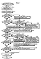
- Fig. 5 is a block diagram showing the construction of the present compiler and related input/output data.
- the present compiler can be roughly divided into three groups.
- the first group generates the serial assembler code 42 from the source code 41 written in a high-level language (the compiler upstream part 10 and the assembler code generation unit 11).
- the second group generates the parallel assembler code 43 and the object code 44a-44b by subjecting the serial assembler code 42 to the parallel scheduling which is unique to the VLIW processor 100 (the constant division unit 12, the parallel scheduling unit 13, the constant combination unit 14, the code output unit 15, and the parallel assembler unit 16).
- the third group generates the final executable code 46 by linking a plurality of relocatable object code 44a and 44b (the linker unit 17).
- the relocation information 45a-45b and location information 40 are related to labels and are input into or output from the linker unit 17.
- the relocation information 45a-45b and location information 40 are used to determine final label addresses and are also input into the constant division unit 12 for use when generating optimal code.
- the input/output data 40-45 and other intermediate language data are stored on a hard disk of the computer system described above as files or are stored in a memory as temporary data.
- the compiler upstream part 10 reads high-level language source code 41 saved in a file format, performs syntactic analysis and semantic analysis on the source code 41, and generates internal format code. Furthermore, as necessary, the internal format code are optimized so that the size of the finally generated executable code and the execution time are reduced.
- the processing of the compiler upstream part 10 is the same as that of the compiler upstream part of an ordinary compiler (a compiler for an ordinary processor, not for a constant reconstructing VLIW processor).
- the assembler code generation unit 11 generates the serial assembler code 42 from the internal format code which was generated and optimized by the compiler upstream part 10.
- the "serial assembler code” is serially arranged assembler instructions for operations and is assembler code for an ordinary processor (a processor including one operation unit).
- the processing of the assembler code generation unit 11 is the same as that of the assembler code generation unit of an ordinary compiler.
- the constant division unit 12 reads the assembler code 42 generated by the assembler code generation unit 11 and divides all long constant use instructions included in the assembler code 42 into divided constant set instructions and divided constant use instructions. That is, long constant use instructions are replaced with two types of instructions (divided constant set instructions and divided constant use instructions). With the two types of instructions, the same process as that of a long constant use instruction is performed. During this replacement process, depending on the length of the long constant included in a long constant use instruction, the long constant use instruction may be replaced with two or more divided constant set instructions and a divided constant use instruction.
- a "long constant” is a constant which is too long to be written within a unit operation field in a VLIW. More specifically, (1) when used by a branch instruction, a long constant is a constant which cannot be written within the first operation field (a branch label expressed by one or more bits), and (2) when used by a transfer/arithmetic logic instruction, a long constant is a constant which cannot be written within a 12-bit operation field shown in Fig. 3B (a constant expressed by 5 or more bits). Also, a "long constant use instruction” is an instruction using a long constant.
- a constant which can be written within a unit operation field in a VLIW which is to say a constant used by a transfer/arithmetic logic instruction and is expressed by 4 or less bits, is called a "short constant”.
- An instruction using a short constant is called a “short constant use instruction”.
- the divided constant use instruction includes a short constant (a constant of 4 or less bits) and therefore is a short constant use instruction.
- Fig. 6 is a flowchart showing the processing of the constant division unit 12.
- the constant division unit 12 performs the following process (steps S2-S4) for each instruction included in the assembler code 42 (steps S1-S5).
- the constant division unit 12 determines the size of a label (the number of bits necessary to express an address indicated by the label) included in an instruction to be processed (hereinafter simply referred to as a "target instruction") (step S2).
- the size of a label when the size of a label can be determined because the label is a local label which is present in the same compile unit of the source code 41 or when the size is explicitly indicated by any information such as the location information 40, the size is added to the label as size information as it is.
- a temporary size is added to the label as label information. Note that in this embodiment, the temporary size is predetermined to be 16 bits which, according to statistical analysis, is the most common address size.
- the constant division unit 12 determines whether the target instruction is a long constant use instruction (step S3).
- the instruction is divided into one or more divided constant set instructions and a divided constant use instruction (step S4).
- the long constant use instruction is a branch instruction
- the long constant (an address indicated by a branch label) is divided into 12-bit parts in order from the least significant bit.
- the constant division unit 12 generates one or more divided constant set instructions, which set obtained divided constants in the constant buffer 107 sequentially from the most significant bit, and a divided constant use instruction (an instruction equivalent to the operation code of a branch instruction).
- the target instruction is replaced with the generated one or more divided constant set instructions and a divided constant use instruction.
- the long constant in the instruction has 19 bits, for instance, the long constant is given leading zeros to be 24 bits (a multiple of 12 bits) and is divided into the upper 12 bits and the lower 12 bits.
- Three instructions in total namely a divided constant set instruction for the upper 12-bit divided constant, a divided constant set instruction for the lower 12-bit divided constant, and a divided constant use instruction, are generated in this order.
- the target instruction is replaced with these generated instructions.
- the constant division unit 12 first removes the equivalent of a short constant (the lower 4 bits) and divides the remaining long constant into 12-bit units starting from its least significant bit.
- the constant division unit 12 generates one or more divided constant set instructions, which set obtained divided constants in the constant buffer 107 sequentially from the most significant bit, and a divided constant use instruction (an instruction including the operation code of the transfer/arithmetic logic instruction and an operand indicating the short constant).
- the target instruction is replaced with the generated instructions.
- the long constant in the instruction has 19 bits, for instance, the long constant is given leading zeros to be 28 bits (12 bits x n + 4 bits) and is divided into the upper 12 bits, the middle 12 bits, and the lower 4 bits.
- Three instructions in total namely a divided constant set instruction for the upper 12-bit divided constant, a divided constant set instruction for the middle 12-bit divided constant, and a divided constant use instruction including the lower 4-bit divided constant, are generated in this order.
- the target instruction is replaced with these generated instructions.
- the parallel scheduling unit 13 receives serial assembler code from which long constant use instructions have been eliminated by the constant division unit 12.
- the parallel scheduling unit 13 detects the parallelism of the serial assembler code at the assembler instruction level and generates parallel assembler code packed into VLIWs corresponding to the three-operation format shown in Fig. 2A or the two-operation format shown in Fig. 2B.
- "parallel assembler code” is assembler code for a VLIW processor, where a sequence of parallel assembler instructions is used to specify a plurality of operations that can be executed in parallel.
- the parallel scheduling unit 13 includes the dependence graph generation unit 20 and the instruction relocation unit 21.
- the dependence graph generation unit 20 generates a dependence graph for the assembler code output from the constant division unit 12.
- the "dependence graph” is a directional graph expressing execution order relations between assembler instructions with links (also called arrows or edges) whose nodes are the instructions and regulates the execution order of instructions in the assembler code.
- Fig. 7 is a flowchart showing the processing of the dependence graph generation unit 20.
- the dependence graph generation unit 20 repeats the processing described below (steps S12-S27) for each instruction in the serial assembler code from which long constant use instructions are eliminated by the constant division unit 12 (steps S11-S29).
- the dependence graph generation unit 20 repeats the following three processes, (1) the generation of a dependence graph based on the exclusive control over the register group 108 (steps S13-S18), (2) the generation of a dependence graph based on the exclusive control over the memory (steps S19-S24), and (3) the generation of a dependence graph based on the exclusive control over the constant buffer 107 (steps S25-S28). These processes are described in more detail below.
- the dependence graph generation unit 20 generates a node corresponding to a target instruction (step S12). More specifically, the dependence graph generation unit 20 generates information relating the target instruction to the node.
- the dependence graph generation unit 20 judges whether the target instruction refers to a register (step S13).
- "referring to a register” indicates that the value of the register is read.
- the previous register definition instruction (a previous instruction which defines the register) is specified and a link from the specified instruction to the target instruction is established (step S14). More specifically, information indicating a link from the node corresponding to the indicated instruction to the node corresponding to the target instruction is generated.
- a "register definition” means that a value in a register is discarded and a new value is set in the register.
- the "previous instruction” means the latest instruction before a target instruction.
- the dependence graph generation unit 20 repeats the steps S13 and S14 for each register. This repetition may also apply to the following steps.
- the dependence graph generation unit 20 judges whether the target instruction defines a register (step S15).
- the previous register control instruction (a previous instruction which controls the register) is specified and it is judged whether the specified instruction is a register definition instruction (step S16).
- register control means the definition and reference of a register.
- step S17 When the judgement result is that the specified instruction is a register definition instruction, a link from the register definition instruction to the target instruction is established (step S17).
- the specified instruction is a register reference instruction, not a register definition instruction
- the previous register definition instruction is specified and links are established to the target instruction from each register reference instruction (instructions for referring to the register) located between the previous register definition instruction and the target instruction (step S18).
- steps S13-S18 The processing related to register references and register definitions described above (steps S13-S18) is also performed for the memory (steps S19-S24).
- the dependence graph generation unit 20 judges whether the target instruction is a divided constant set instruction (step S25).
- a link from the previous constant buffer control instruction to the target instruction is established (step S26).
- a "constant buffer control instruction” is an instruction for controlling (defining and referring to) the constant buffer 107, namely a divided constant set instruction and a divided constant use instruction.
- the dependence graph generation unit 20 judges whether the target instruction is a divided constant use instruction (step S27).
- step S28 When the target instruction is a divided constant use instruction, a link from the previous constant buffer control instruction to the target instruction is established (step S28).
- each divided constant set instruction and divided constant use instructions that accesses the constant buffer 107 is an instruction for referring to and also defining the constant buffer 107. That is, the constant buffer 107 includes a shift register, so that a divided constant set instruction is a shift & set instruction (a reference and definition instruction). Because the content of the constant buffer 107 is cleared immediately after the content is referred to, a divided constant use instruction is a reference and definition instruction.
- the instruction relocation unit 21 relocates instructions in the serial assembler code output from the constant division unit 12 by packing the instructions in VLIW units of the target processor 100. When doing so, the instruction relocation unit 21 relocates instructions so that the largest possible number of instructions are executed in parallel, thereby reducing the execution time.
- Fig. 8 is a flowchart showing the processing of the instruction relocation unit 21.
- the instruction relocation unit 21 repeats the following process (steps S42-S50) until all instructions in the serial assembler code are relocated (all instructions are packed in VLIW units and are output from the parallel scheduling unit 13) (steps S41-S51).
- the instruction relocation unit 21 checks the dependence graph to classify all instructions that can be output at the present time into an outputable instruction group (step S42).
- an "outputable instruction” is an instruction which does not depend on a previous instruction and so can be executed (outputted) independently.
- the examples of outputable instructions are (1) a target instruction to which there is no link in the dependence graph and (2) a target instruction whose link source node corresponds to instructions having been output or to divided constant set instructions in the dependence graph.
- the "outputable instruction group” is composed of all instructions which can be output at the present time.
- the outputable instruction group includes target instructions whose link source is a divided constant set instruction. This is because even if a VLIW includes a divided constant set instruction and a divided constant use instruction, these instructions can be replaced with a single instruction by the constant combination unit 14 as described later, so that these instructions can be executed without causing any problems.
- step S42 After an outputable instruction group is generated (step S42), a process for selecting and deleting one instruction from the group (steps S45-S48) is repeated until all instructions have been selected and deleted from the group (steps S43-S49).
- step S43-S49 the process exits from the loop (steps S43-S49), generates another outputable instruction group (step S42), and repeats the same process (steps S45-S48) (steps S43-S49). This is because by the time instructions composing the generated VLIW are deleted from the outputable instruction group, new outputable instructions may have been generated.
- the instruction relocation unit 21 judges whether a VLIW can be made from instructions in an output schedule instruction group (whether any more instructions can be inserted into the VLIW) (step S44).
- output schedule instructions are instructions which can be included in a generated single VLIW and are executable in parallel, while the “output schedule instruction group” temporarily holds instructions to accumulate the maximum number of output schedule instructions (the maximum number of output schedule instructions which can be arranged in a VLIW). That is, only instructions shifted from the outputable instruction group to the output schedule instruction group are output from the parallel scheduling unit 13 as instructions which compose a generated VLIW.
- the instruction relocation unit 21 selects an instruction from the outputable instruction group that will result in the execution time and the code size being reduced (step S45). More specifically, the instruction relocation unit 21 calculates estimates for the total number of VLIWs generated from a basic block by referring to the dependence graph and selects the instruction that results in the lowest estimate.
- the instruction relocation unit 21 judges whether the selected instruction (a target instruction) can be included in the output schedule instruction group (step S46). Here, if one or more instructions have been included in the output schedule instruction group by this time, the instruction relocation unit 21 judges whether the included instructions and the target instruction can compose a VLIW (whether a VLIW can be output) (step S46).
- the instruction relocation unit 21 judges that these instructions cannot be output.
- the instruction relocation unit 21 judges that instructions cannot be output. This prevents the generation of an erroneous code, where a divided constant use instruction is output without divided constant set instructions.
- the instruction relocation unit 21 judges that an instruction included in the output schedule instruction group and a target instruction can compose a VLIW in step S46, the target instruction is transferred from the outputable instruction group to the output schedule instruction group (steps S47 and S48).
- step S48 when the instruction relocation unit 21 judges that an instruction included in the output schedule instruction group and a target instruction cannot compose a VLIW in step S46, the target instruction cannot be output at this time and so is eliminated from the outputable instruction group (step S48).
- step S50 When the instruction relocation unit 21 judges that a VLIW can be made from instructions in the output schedule instruction group in step S44, the instructions are eliminated from the output schedule instruction group and are output as a VLIW (step S50). Note that when the process proceeds from step S49 to step S50, there are cases where all operation fields of a VLIW cannot be filled with instructions remaining in the output schedule instruction group. In this case, a VLIW whose blank operation fields are filled with no-operation instructions (nop) is output.
- serial assembler code input into the parallel scheduling unit 13 is packed into VLIWs to generate parallel assembler code which is then output.
- the constant combination unit 14 replaces these instructions with a long constant use instruction which it obtains by combining these instructions.
- the constant combination unit 14 replaces these instructions with a divided constant set instruction which it obtains by combining these instructions. This corresponds to a case where the constant division unit 12 need not have divided a long constant (need not have arranged divided constants in a plurality of VLIWs).
- the code output unit 15 converts internal-format assembler code that has been combined (replaced) by the constant combination unit 14 to a text-format assembler code, and outputs the converted code as files (the parallel assembler code 43).
- the parallel assembler unit 16 converts the parallel assembler code 43 output from the code output unit 15 into a machine language dedicated to the VLIW processor 100 for which the present compiler is used, and generates the object code 44a-44b and the relocation information 45a-45b. During this process, the format information to be located in the first field 51 of a VLIW is determined. In the case of a VLIW including one or more divided constant set instructions, for instance, the parallel assembler unit 16 generates machine code for the fields having only a divided constant and the format information indicating the fields.
- Each of the relocation information 45a-45b is composed of information indicating the name of a label for each object code 44a, the address of an instruction using the label, and the size of the label.
- This label size is the size determined by the constant division unit 12 (the label size determined in step S2 shown in Fig. 6), and is a temporary value (16 bits in the above example) in the case of an external label.
- the linker unit 17 links the plurality of relocatable object code 44a-44b generated in different compile units, determines undetermined labels included in the object code, and generates the executable code 46 and the relocation information 40 for the VLIW processor 100.
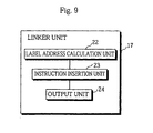
- Fig. 9 is a block diagram showing the detailed construction of the linker unit 17.
- the linker unit 17 includes the label address calculation unit 22, the instruction insertion unit 23, and the output unit 24.
- the label address calculation unit 22 calculates an address of each label after the plurality of relocatable object code 44a-44b input into the linker unit is linked. By doing so, the size of each label is also determined. This process is the same as that by a label address calculation unit of an ordinary compiler.
- the instruction insertion unit 23 inserts the required divided constant set instruction to cope with the situation.
- Fig. 10 is a flowchart showing the processing of the instruction insertion unit 23.
- the instruction insertion unit 23 sequentially fetches each label out of the object code 44a-44b input into the linker unit 17 and repeats the following process (steps S62-S64) for each of the fetched labels (steps S61-S65).
- relocation information of a fetched label (a target label) is read from the relocation information 45a-45b input into the linker unit 17 (step S62).
- the linker unit 17 judges whether the size calculated by the label address calculation unit 22 is greater than that of the target label indicated by the read relocation information (step S63).
- one or more divided constant set instructions are generated to store divided constants corresponding to the difference between these sizes.
- a new VLIW including the generated divided constant set instructions and a no-operation instruction is inserted immediately before the VLIW including the instruction that uses the target label (step S64).
- the output unit 24 generates the location information 40 indicating the size of each label determined by the label address calculation unit 22 and a list of instructions that refer to the labels, and outputs the location information 40 with the executable code 46 obtained after the processing of the instruction insertion unit 23.
- the following description concerns an operation of the constant division unit 12 and the parallel schedule unit 13 where the serial assembler code 42 shown in Fig. 11A is generated by the assembler code generation unit 11 and is input into the constant division unit 12.
- the assembler code 401 and 402 shown in Fig. 11A are described below.
- the value in the register R1 is added to the value in the register R2 and the result is stored in the register R2.
- the constant division unit 12 repeats the processing for dividing long constants (steps S1-S5) for each of three instructions shown in Fig. 11A. However, in this example, the instructions 400 and 401 include neither labels nor long constants and are therefore not processed.
- the constant division unit 12 cannot determine the size of the label "LabeL" in the instruction 402 and so assumes the size is 16 bits (step S2).
- the constant division unit 12 judges that the instruction 402 is a long constant use instruction (step S3) and replaces this long constant use instruction 402 with one or more divided constant set instructions and a divided constant use instruction (step S4).
- Fig. 11B shows code generated by the constant division unit 12 when the serial assembler code 42 shown in Fig. 11A is input.
- the long constant use instruction 402 in Fig. 11A is replaced with the divided constant set instruction 405 and the divided constant use instruction 406.
- the dependence graph generation unit 20 repeats the same process for each of three instructions shown in Fig. 11B (steps S11-S29).
- Fig. 12 shows the dependence graph 600 generated by the dependence graph generation unit 20 in the case where the serial assembler code shown in Fig. 11B is input into the parallel scheduling unit 13.
- the dependence graph generation unit 20 generates the node 601 corresponding to this instruction 403 (step S12).
- this instruction 403 refers to the register R0
- a link from a previous instruction defining the register R0 should be established (steps S13 and S14). However, there are no preceding instructions, so that this link cannot be established.
- this instruction 403 defines the register R1
- a previous instruction controlling the register R1 should be specified (steps S15 and S16). However, there are no preceding instructions, so that a link cannot be established.
- this example uses only one basic block (a process routine having one entrance and one exit) for ease of explanation.
- the plurality of basic blocks can be processed by using virtual nodes indicating preceding basic blocks and following basic blocks.
- the instruction 404 is to be processed next and so the dependence graph generation unit 20 generates node 603 corresponding to this instruction 404 (step S12).
- the dependence graph generation unit 20 specifies the previous instruction 403 defining the register R1 and establishes the link 602 from the instruction 403 to the instruction 404 (steps S13 and S14).
- the previous instruction controlling the register R2 should be specified (steps S15 and S16). However, there is no such preceding instruction, so that a link is not established.
- the instruction 405 is to be processed next and so the dependence graph generation unit 20 generates the node 604 corresponding to this instruction 405 (step S12).
- the instruction 405 does not control a register or memory and therefore is not subjected to the link process in steps S13-S24.
- the instruction 405 is a divided constant set instruction, so that the dependence graph generation unit 20 attempts to specify a previous constant buffer control instruction (steps S25 and S26). However, there is no such preceding instruction, and therefore a link is not established.
- the instruction 406 is to be processed and the dependence graph generation unit 20 generates the node 606 corresponding to this instruction 406 (step S12).
- the dependence graph generation unit 20 attempts to specify a previous instruction controlling the register R3 (steps S15 and S16). However, there is no such preceding instruction, and therefore a link is not established.
- the instruction 406 is a divided constant use instruction so that the dependence graph generation unit 2 0 specifies the previous constant buffer control instruction 405 and establishes the link 605 from the instruction 405 to the instruction 406 (steps S27 and S28).
- the instruction relocation unit 21 relocates the serial assembler code shown in Fig. 11B in parallel.
- the following is a description of the operation of the instruction relocation unit 21 in this case, with reference to the flowchart shown in Fig. 8.
- the instruction relocation unit 21 repeats the scheduling cycle (steps S41-S51) including a process for generating the outputable instruction group (step S42) and a process for consuming one instruction in the generated outputable instruction group at a time (step S43-S50).
- the instruction relocation unit 21 In the first scheduling cycle, the instruction relocation unit 21 generates a group composed of the three instructions 403, 405, and 406 as the outputable instruction group (step S42). This is because the instructions 403 and 405 are instructions without links from other nodes to their nodes, and the instruction 406 corresponds to a node whose link source node corresponds to a divided constant set instruction.
- step S45 There is no instruction in the output schedule instruction group, so that the instruction relocation unit 21 judges that a VLIW cannot be made from instructions in the output schedule instruction group in step S44 and the process proceeds to the first consumption cycle by selecting an optimal instruction (step S45).
- the instruction 403 is selected.
- the instruction relocation unit 21 moves the selected instruction 403 into the output schedule instruction group (step S47) and eliminates the instruction 403 from the outputable instruction group (step S48).
- the output schedule instruction group does not include enough instructions to fill a VLIW at the present time, so that instruction relocation unit 21 judges that a VLIW cannot be made from instructions in the output schedule instruction group in step S44.
- the instruction relocation unit 21 selects the instruction 405 as an optimal instruction (step S45).
- Both the selected instructions 405 and 403 in the output schedule instruction group are 12-bit instructions and so may construct a VLIW. Therefore, the instruction relocation unit 21 moves the instruction 405 into the output schedule instruction group (step S47) and eliminates the instruction 405 from the outputable instruction group (step S48).
- the instruction relocation unit 21 judges that a VLIW can be made from instructions in the output schedule instruction group in step S44, eliminates these instructions 403 and 405 from the output schedule instruction group, and outputs a VLIW including these instructions (step S50) .
- the instruction relocation unit 21 selects the instruction 406, instead of the instruction 405, as an optimal instruction in the second consumption cycle (step S45), the divided constant set instruction 405 from which a link is established to the node of the instruction 406 has not been output and is not included in the output schedule instruction group. Therefore, the instruction relocation unit 21 judges that an instruction included in the output schedule instruction group and a target instruction cannot compose a VLIW in step S46 and the instruction 406 is eliminated from the outputable instruction group. As a result, the same VLIW (the VLIW including the instructions 403 and 405) is output in this case.
- Fig. 11C shows VLIWs (parallel assembler code) generated by the instruction relocation unit 21 when the serial assembler code shown in Fig. 11B is input into the parallel scheduling unit 13. Note that code in the first field 51 of a VLIW is omitted for ease of explanation.
- the first scheduling cycle generates the VLIW 407 shown in Fig. 11C.
- the second scheduling cycle starts with the instruction 406 remaining in the outputable instruction group.
- the instruction relocation unit 21 newly adds the instruction 404 to the outputable instruction group (step S42). This is because the instruction 403 corresponds to the node from which a link is established to the node of the instruction 404. As a result, an outputable instruction group composed of the instructions 404 and 406 is generated.
- step S45 There is no instruction in the output schedule instruction group so that the instruction relocation unit 21 judges that a VLIW cannot be made from instructions in the output schedule instruction group in step S44 and the process proceeds to the first consumption cycle by selecting an optimal instruction (step S45).
- the instruction relocation unit 21 selects the instruction 404.
- step S47 There is no instruction in the output schedule instruction group in this case, so that the instruction relocation unit 21 moves the instruction 404 into the output schedule instruction group (step S47) and eliminates the instruction 404 from the outputable instruction group (step S48).
- the output schedule instruction group includes the instructions 404 and 406 at the present time, so that the instruction relocation unit 21 judges that a VLIW can be made from instructions in the output schedule instruction group in step S44.
- the instructions 404 and 406 are eliminated from the output schedule instruction group and are output as the second VLIW (step S50). That is, the second scheduling cycle generates the VLIW 408 shown in Fig. 11C.
- the instruction relocation unit 21 packs all instructions input into the parallel scheduling unit 13 in VLIWs which it then outputs (steps S41-S51). Then the instruction relocation unit 21 terminates its scheduling process.
- VLIWs shown in Fig. 11C are generated from the serial assembler code shown in Fig. 11A by the processing of the constant division unit 12 and the parallel scheduling unit 13. This process is compared with the case of an ordinary compiler to demonstrate the characteristics of the present compiler.
- Fig. 13 is a block diagram showing the construction of the ordinary compiler.
- the ordinary compiler does not have the functions equivalent to the constant division unit 12 and the constant combination unit 14. Therefore, the ordinary compiler does not have the functions equivalent to the other elements 910-917, 920, and 921.
- the assembler code generation unit 911 when the assembler code generation unit 911 generates the serial assembler code shown in Fig. 11A, for instance, the serial assembler code is input into the parallel scheduling unit 913 as it is. As a result, the dependence graph generation unit 920 generates the dependence graph 925 shown in Fig. 14.
- the instruction relocation unit 921 relocates the instructions shown in Fig. 11A according to the dependence graph 925. As shown in Fig. 14, the instructions 400 and 401 depend on each other and so cannot coexist (cannot construct a VLIW). The instruction 402 is 24 bits long so that the instruction 402 cannot coexist with other instructions 400 and 401. Therefore, the instruction relocation unit 921 generates three VLIWs 930-932 shown in Fig. 15.
- the code size of the parallel assembler code generated by the ordinary compiler is greater than that of the embodiment by one VLIW. Therefore, one more cycle is required for the execution of the code generated by the ordinary compiler.
- the compiler of the embodiment divides the VLIW 932 in Fig. 15 into small instructions (one or more divided constant set instructions and a divided constant use instruction) and the small instructions are arranged into the VLIWs 930 and 931 to fill the redundant areas in these VLIWs.
- Figs. 17A-17G show a series of specific code and related information for the explanation of the operation of the linker unit 17.
- Fig. 17A shows the serial assembler code 42 generated by the assembler code generation unit 11 of Example 2.
- Fig. 17B shows code generated by the constant division unit 12 to which the serial assembler code 42 is input.
- Fig. 17C shows parallel assembler code generated by the parallel scheduling unit 13 to which the generated code is input.
- Figs. 17D and 17E show the object code 44a and relocation information 45a generated by the parallel assembler unit 16 to which the generated parallel assembler code is input.
- Figs. 17F and 17G show the executable code 46 and the location information 40 generated by the linker unit 17 to which the object code 44a and the relocation information 45a are input.
- Figs. 17A-17C show additional information indicated by codes following the sign "@", where the additional information is generated together with each instruction.
- This additional information includes an identifier for specifying each instruction and information related to divided constants.
- the additional information "@ID numeral" shown in Fig. 17A is the identifier of an instruction (an instruction identifier) in the same row.
- the additional information "LbU12" and “LbL4" represent the upper 12 bits and the lower 4 bits of the label "LabeL", respectively
- the additional information "S16” (the size information) indicates that the label "LabeL” having been divided with its size assumed to be 16 bits
- the additional information "M” indicates that the present instruction is the first one in the instructions to store divided pieces of the label "LabeL” into the constant buffer 107.
- the instruction "DS" 414 shown in Fug. 17A is a dummy instruction for maintaining a storage area (4 bytes) for storing the label "LabeL”.
- the object code 44a shown in Fig 17D and the relocation information 45a shown in Fig. 17E are input into the linker unit 17.
- the "location information" in the object code indicates relative addresses of each instruction by offsets (in byte units) from the start of a specific memory area (a segment or a section).
- the sign “0x” indicates that the number following the sign is expressed in hexadecimal.
- the signs “LabeL:12u” and “LabeL:4L” represent the upper 12 bits and the lower 4 bits of the label “LabeL”, respectively, the two pieces being divided constants.
- the relocation information 45a is composed of the "label", the "location information” indicating the location of an instruction referring to the label, and the "additional information" accompanying the instruction.
- the location information is composed of an address of a VLIW and a numeral specifying the location of a unit operation field in the VLIW including an instruction referring to the label, where the VLIW address values differ from each other by 32 bits (4 bytes).
- the label "LabeL” is referred to by an instruction arranged in the third operation field of the VLIW located at the relative address "0x1000" and this VLIW includes the additional information "ID102. LbU12. S16. M”.
- the label “LabeL” is also referred to by the instruction arranged in the third operation field of the VLIW located at the relative address "0x1004" and this VLIW includes the additional information "ID102. LbL4. S16".
- the label address calculation unit 22 calculates that the final size of the label "LabeL" is 28 bits by referring to other simultaneously input object code.
- the instruction insertion unit 23 sets the label "LabeL” as the target label (step S61) and extracts relocation information of the target label "LabeL” from the relocation information 45a input into the linker unit 17 (step S62) .
- the instruction insertion unit 23 compares the size information "S16" included in the additional information of the relocation information with the size "28 bits" of the target label calculated by the label address calculation unit 22 (step S63).
- the instruction insertion unit 23 specifies one out of the relocation information 429 and 430 for the label "LabeL" shown in Fig. 17E which includes the additional information "M" (in this example, the relocation information 429). Then the instruction insertion unit 23 inserts a new VLIW including a no-operation code (nop) and one or more divided constant set instructions immediately before the VLIW 425 corresponding to the location information (0x1000. 3) (step S64).
- a no-operation code no-operation code
- the resulting VLIW 431 is additionally inserted immediately before the VLIW 432.
- the label "LabeL:12u” indicates the upper 12 bits of the 28-bit label “LabeL”, that is bits exceeding the 16 bits indicated by the size information of the relocation information.
- the divided constant "LabeL:12m” indicates middle 12 bits of the 28-bit label "LabeL”.
- the output unit 24 generates the location information 40 including the label size determined by the label address calculation unit 22 and outputs the location information with the executable code 46 obtained after the instruction insertion unit 23 performs the instruction insertion process (Fig. 17F).
- the location information 436 of the label "LabeL” includes the label size "28" and the identifier "@ID102" of the instruction referring to the label.
- this output from the linker unit becomes the final executable code 46.
- Figs. 18A-18E show code and related information generated by each component element when the generated location information 40 is fed back into the constant division unit 12.
- Fig. 18A shows the code generated by the constant division unit 12 from the serial assembler code 42 shown in Fig. 17A and the location information 40 shown in Fig. 17G.
- Fig. 18B shows parallel assembler code generated by the parallel scheduling unit 13 from the generated code.
- Figs. 18C and 18D respectively show the object code 44a and the relocation information 45a generated by the parallel assembler unit 16 from the parallel assembler code.
- Fig. 18E shows the executable code 46 generated by the linker unit 17 from the object code 44a and the relocation information 45a.
- the constant division unit 12 determines that the size of the external label of the instruction with the instruction identifier "ID102" is 28 bits (step S2 in Fig. 6), and divides the 28-bit label "LabeL” (steps S3 and S4).
- the instruction 412 in Fig. 17A is replaced by three instructions 442-444 shown in Fig. 18A.
- the additional information "LbM12" of the instruction 443 indicates that this instruction refers to the middle 12 bits of the label "LabeL".
- the parallel scheduling unit 13 generates parallel assembler code without no-operation codes (nop) (see Fig. 18B) by generating a dependence graph and relocating instructions according to the procedure shown in Figs. 7 and 8.
- the parallel assembler unit 16 generates the object code 44a corresponding to the parallel assembler code (see Fig. 18C) and the relocation information 45a (see Fig. 18D). Note that the legend "LabeL.12m” shown in Fig. 18C represents the middle 12 bits of the label "LabeL”.
- the label address calculation unit 22 calculates that the size of the label "LabeL” is 28 bits again and so the instruction insertion unit 23 does not insert any more instruction concerning the label "LabeL” (step S63 in Fig. 10). Therefore, the executable code 46 shown in Fig. 18E is generated.
- the code size of the executable code optimized by sending back the location information 12 to the constant division unit 12 is smaller than that of the other executable code (see Fig. 17F) by one VLIW.
- the executable code generated in this manner can be transported to target environments equipped with the VLIW processors 100 by means of a recording medium, such as a floppy disk, a CD-ROM, or a semiconductor memory, or through communications via a transmission medium.
- a recording medium such as a floppy disk, a CD-ROM, or a semiconductor memory
- Fig. 19A shows the serial assembler code 42 generated by the assembler code generation unit 11 of Example 3.
- the execution control of the VLIW processor 100 moves to the branch label " _func".
- the size of this branch label "_func" is 12 bits long and the argument R1 is transferred to the function " _func" when control branches to the function.
- Fig. 19B shows the code generated by the constant division unit 12 from the serial assembler code 42 shown in Fig. 19A.
- the branch instruction 473 is accompanied by the 12-bit branch label " _func" so that the instruction 473 is divided into the divided constant set instruction 477 for storing the branch label " _func" in the constant buffer 107 and the divided constant use instruction 478 equivalent to the operation code "caLL" of the branch instruction 473.
- Fig. 19C shows a dependence graph generated by the dependence graph generation unit 20 in the case where the code shown in Fig. 19B is input.
- the branch instruction 478 depends on the instruction 474.
- Fig. 19D shows the outputable instruction group and the output schedule instruction group temporarily generated by the instruction relocation unit 21 in the case where the code shown in Fig. 19B and the dependence graph shown in Fig. 19C are input.
- the branch instruction (caLL) 478 is included in the output schedule instruction group.
- Fig. 19E shows the parallel assembler code generated by the instruction relocation unit 21. This figure also shows the code in the first field 51 of VLIWs.
- the constant division unit 12 and the parallel scheduling unit 13 of the present compiler generate the parallel assembler code of two VLIWs shown in Fig. 19E from the serial assembler code 42 shown in Fig. 19A.
- Fig. 16 shows parallel assembler code which may be generated by the ordinary compiler.
- the ordinary compiler cannot divide the branch instruction 473 shown in Fig. 19A so that at least a 13-bit field, namely successive two fields, is required for this instruction. Therefore, parallel assembler code for three VLIWs 940-942 is generated and there are many redundant areas in these VLIWs.
- Fig. 20A shows the serial assembler code 42 generated by the assembler code generation unit 11 of Example 4.
- Fig. 20B shows the code generated by the constant division unit 12 from the serial assembler code 42 shown in Fig. 20A.
- the branch instruction 503 is divided into the divided constant set instruction 507 and the divided constant use instruction 508 like the Example 3.
- Fig. 20C shows a dependence graph generated by the dependence graph generation unit 20 from the code shown in Fig. 20B.
- Fig. 20D shows the outputable instruction group and the output schedule instruction group temporarily generated by the instruction relocation unit 21 from the code shown in Fig. 20B and the dependence graph shown in Fig. 20C.
- the divided constant set instruction 507 and the divided constant use instruction 508 are included in the output schedule instruction group.
- Fig. 20E shows the parallel assembler code generated by the instruction relocation unit 21.
- the parallel assembler code is composed of two VLIWs 509 and 510.
- the instructions 507 and 508 generated from the branch instruction 503 are arranged in the first field 5 1 and the second field 52 of the VLIW 510, respectively.
- Fig. 20F shows the code generated by the constant combination unit 14 from the parallel assembler code shown in Fig. 20E.
- the constant combination unit 14 detects that the divided constant set instruction 507 and the divided constant use instruction 508 generated from the same long constant use instruction (the branch instruction 503) are arranged in the same VLIW 510. Accordingly, the constant combination unit 14 replaces these instructions 507 and 508 with a long constant use instruction (an instruction of the same format as the original branch instruction 503) obtained by combining the instructions 507 and 508. This solves problems caused by the constant division unit 12 unnecessarily dividing a constant (since divided constants need not have arranged the divided constants in a plurality of VLIWs).
- the target processor of the compiler of the embodiment is similar to the VLIW processor disclosed by Japanese Laid-Open Patent Application H9-159058 or H9-159059.
- the present compiler may be used for any constant reconstruction processor executing a program which is made by dividing instructions into parts and arranging the divided instructions parts in a plurality of VLIWs.
- VLIWs While the compiler of the embodiment generates VLIWs in two formats shown in Figs. 2A and 2B, this compiler may generates VLIWs in any type of format, such as VLIWs which each are composed of three 16-bit operation fields. This is because the present invention is a technique for dividing constants included in instructions and performing parallel scheduling according to the size of operation fields of VLIWs.
- the VLIW processor 100 which is the target processor of the compiler of the embodiment, includes a 32-bit shift register (the constant buffer 107).
- the shift register is filled with 0s immediately after a value stored in the shift register is referred to.
- the present invention is not limited to the processor including the constant buffer 107 functioning like this.
- the present invention may be used for a processor including a constant buffer for storing two or more independent constants and using instructions that explicitly indicate storage areas of the constants and clears the used content. More specifically, when a divided constant set instruction is generated, an instruction for indicating the storage area may also be generated. And when a divided constant use instruction is generated, an instruction for clearing the content may also be generated.
- fixed values such as 4 bits or 12 bits are used when constants are divided.
- the present invention is not limited to these values.
- the size of a label when the size of a label cannot be determined, the size is assumed to be the most common address size (16 bits). However, the size may be assumed to be the maximum address size of the target processor. Also, when a constant whose size cannot be determined is an operand for a transfer/arithmetic logic instruction, the size of the constant may be assumed to be the maximum constant size of the target processor or to be the most common constant size. The assumed size may be pre-stored as a default value or may be specified by a user as an option when the compiler is activated.
- the function of the constant division unit 12 can be expressed from two points of view. That is, from the first point of view, the constant division unit 12 functions as a means for dividing each instruction including a constant among input instructions (each long constant use instruction) into a plurality of instructions (one or more divided constant set instructions and a divided constant use instruction) as shown in Fig. 21A.
- the constant division unit 12 functions as a means for dividing each constant in input instructions (each 28-bit long constant) into a plurality of parts and for generating a plurality of instructions respectively including the divided constant parts (a divided constant set instruction for the upper 12-bit divided constant, a divided constant set instruction for the middle 12-bit divided constant, and a divided constant use instruction including the lower 4-bit short constant) according to the input instructions, as shown in Fig. 21B.
- Example 1 the instruction relocation unit 21 adds the instruction 404 to the instruction 406 remaining in the outputable instruction group in the first scheduling cycle to proceed to the second cycle. However, the instruction relocation unit 21 may clear the content of the outputable instruction group and recalculate for each cycle.
- executable code generated by the compiler of the embodiment can be transported to a target environment which executes the generated code by means of a recording medium, such as a floppy disk, a CD-ROM, or a semiconductor memory, or through communications via a transmission medium.
- a recording medium such as a floppy disk, a CD-ROM, or a semiconductor memory
- Fig. 22 shows a simplified content of the CD-ROM 200 recording the VLIW sequence 201 shown in Fig. 18E and the VLIW sequence 202 shown in Fig. 9E generated by the compiler of the embodiment.
- the two VLIWs 458 and 459 include constants to be combined and stored in the storage buffer of the processor implicitly indicated by the VLIW sequence.
- the VLIW 460 follows both the VLIWs 458 and 459 and is the first VLIW to refer to the storage buffer.
- This VLIW 460 includes a constant and the instruction (Ld) for using a constant obtained by combining the constant and the constants included in the two or more VLIWs.
- the VLIW 480 includes the constant (sfst) to be stored into the storage buffer of the processor implicitly indicated by the VLIW sequence.
- the compiler itself of the present invention may also be stored in a recording medium, such as a floppy disk, a CD-ROM, or a semiconductor memory, and be distributed, like executable code obtained by the compiler.
- a recording medium such as a floppy disk, a CD-ROM, or a semiconductor memory
Priority Applications (1)
| Application Number | Priority Date | Filing Date | Title |
|---|---|---|---|
| EP05077437A EP1628213A3 (en) | 1997-08-29 | 1998-08-28 | VLIW processor |
Applications Claiming Priority (3)
| Application Number | Priority Date | Filing Date | Title |
|---|---|---|---|
| JP23514497 | 1997-08-29 | ||
| JP235144/97 | 1997-08-29 | ||
| JP23514497A JP3327818B2 (ja) | 1997-08-29 | 1997-08-29 | プログラム変換装置及び記録媒体 |
Related Child Applications (1)
| Application Number | Title | Priority Date | Filing Date |
|---|---|---|---|
| EP05077437A Division EP1628213A3 (en) | 1997-08-29 | 1998-08-28 | VLIW processor |
Publications (3)
| Publication Number | Publication Date |
|---|---|
| EP0899656A2 EP0899656A2 (en) | 1999-03-03 |
| EP0899656A3 EP0899656A3 (en) | 2002-01-02 |
| EP0899656B1 true EP0899656B1 (en) | 2005-12-28 |
Family
ID=16981713
Family Applications (2)
| Application Number | Title | Priority Date | Filing Date |
|---|---|---|---|
| EP05077437A Withdrawn EP1628213A3 (en) | 1997-08-29 | 1998-08-28 | VLIW processor |
| EP98306914A Expired - Lifetime EP0899656B1 (en) | 1997-08-29 | 1998-08-28 | Program conversion apparatus for constant reconstructing VLIW processor |
Family Applications Before (1)
| Application Number | Title | Priority Date | Filing Date |
|---|---|---|---|
| EP05077437A Withdrawn EP1628213A3 (en) | 1997-08-29 | 1998-08-28 | VLIW processor |
Country Status (5)
| Country | Link |
|---|---|
| US (1) | US6367067B1 (ja) |
| EP (2) | EP1628213A3 (ja) |
| JP (1) | JP3327818B2 (ja) |
| KR (1) | KR100496946B1 (ja) |
| DE (1) | DE69832932T2 (ja) |
Families Citing this family (29)
| Publication number | Priority date | Publication date | Assignee | Title |
|---|---|---|---|---|
| JP3327818B2 (ja) | 1997-08-29 | 2002-09-24 | 松下電器産業株式会社 | プログラム変換装置及び記録媒体 |
| JP2000132404A (ja) | 1998-10-22 | 2000-05-12 | Matsushita Electric Ind Co Ltd | 命令列最適化装置 |
| US6457173B1 (en) * | 1999-08-20 | 2002-09-24 | Hewlett-Packard Company | Automatic design of VLIW instruction formats |
| GB2358491A (en) * | 1999-09-03 | 2001-07-25 | Sgs Thomson Microelectronics | A relocation format for linking |
| US6675377B1 (en) * | 1999-09-13 | 2004-01-06 | Matsushita Electric Industrial Co., Ltd. | Program conversion apparatus |
| JP2002091762A (ja) * | 2000-09-14 | 2002-03-29 | Denso Corp | プログラム生成装置 |
| US7331040B2 (en) * | 2002-02-06 | 2008-02-12 | Transitive Limted | Condition code flag emulation for program code conversion |
| GB0202728D0 (en) * | 2002-02-06 | 2002-03-27 | Transitive Technologies Ltd | Condition code flag emulation for program code conversion |
| SE521753C2 (sv) * | 2002-02-08 | 2003-12-02 | Xelerated Ab | Förfarande och system för att uppfylla realtidskrav för en dataprocessor |
| US8141068B1 (en) * | 2002-06-18 | 2012-03-20 | Hewlett-Packard Development Company, L.P. | Compiler with flexible scheduling |
| EP1378824A1 (en) * | 2002-07-02 | 2004-01-07 | STMicroelectronics S.r.l. | A method for executing programs on multiple processors and corresponding processor system |
| JP3847672B2 (ja) | 2002-07-03 | 2006-11-22 | 松下電器産業株式会社 | コンパイラ装置及びコンパイル方法 |
| AU2003253159A1 (en) | 2002-09-24 | 2004-04-19 | Koninklijke Philips Electronics N.V. | Apparatus, method ,and compiler enabling processing of load immediate instructions in a very long instruction word processor |
| US7444620B2 (en) * | 2003-02-28 | 2008-10-28 | Bea Systems, Inc. | Systems and methods for a common runtime container framework |
| JP2005173645A (ja) * | 2003-12-05 | 2005-06-30 | Ibm Japan Ltd | プログラム開発支援装置、プログラム開発支援方法、プログラム、及び、記録媒体 |
| JP4283131B2 (ja) * | 2004-02-12 | 2009-06-24 | パナソニック株式会社 | プロセッサ及びコンパイル方法 |
| US7401329B2 (en) * | 2005-04-25 | 2008-07-15 | Arm Limited | Compiling computer programs to exploit parallelism without exceeding available processing resources |
| US20070083736A1 (en) * | 2005-10-06 | 2007-04-12 | Aravindh Baktha | Instruction packer for digital signal processor |
| JP4879589B2 (ja) * | 2006-01-20 | 2012-02-22 | パナソニック株式会社 | コンパイラ装置 |
| KR20090009981A (ko) * | 2006-06-15 | 2009-01-23 | 닛본 덴끼 가부시끼가이샤 | 프로세서 및 명령 제어 방법 |
| US20100223596A1 (en) * | 2007-10-03 | 2010-09-02 | Takeshi Inuo | Data processing device and method |
| EP2282268B1 (en) * | 2009-07-23 | 2012-11-21 | STMicroelectronics Srl | Interfacing device and method, for example for systems-on-chip |
| JP5059174B2 (ja) * | 2010-08-10 | 2012-10-24 | 株式会社東芝 | プログラム変換装置、およびそのプログラム |
| US9477476B2 (en) * | 2012-11-27 | 2016-10-25 | Qualcomm Incorporated | Fusing immediate value, write-based instructions in instruction processing circuits, and related processor systems, methods, and computer-readable media |
| US9424045B2 (en) | 2013-01-29 | 2016-08-23 | Arm Limited | Data processing apparatus and method for controlling use of an issue queue to represent an instruction suitable for execution by a wide operand execution unit |
| US9348596B2 (en) | 2013-06-28 | 2016-05-24 | International Business Machines Corporation | Forming instruction groups based on decode time instruction optimization |
| US9372695B2 (en) * | 2013-06-28 | 2016-06-21 | Globalfoundries Inc. | Optimization of instruction groups across group boundaries |
| US9875107B2 (en) * | 2015-01-19 | 2018-01-23 | International Business Machines Corporation | Accelerated execution of execute instruction target |
| DE102018113475A1 (de) * | 2018-06-06 | 2019-12-12 | Infineon Technologies Ag | Rechenwerk zum rechnen mit maskierten daten |
Family Cites Families (17)
| Publication number | Priority date | Publication date | Assignee | Title |
|---|---|---|---|---|
| JP2835103B2 (ja) * | 1989-11-01 | 1998-12-14 | 富士通株式会社 | 命令指定方法及び命令実行方式 |
| JP3004108B2 (ja) * | 1991-11-27 | 2000-01-31 | 株式会社東芝 | 情報処理装置 |
| JPH05197545A (ja) * | 1991-12-10 | 1993-08-06 | Mitsubishi Electric Corp | マイクロコンピュータ |
| US5557761A (en) * | 1994-01-25 | 1996-09-17 | Silicon Graphics, Inc. | System and method of generating object code using aggregate instruction movement |
| JP3430635B2 (ja) * | 1994-06-17 | 2003-07-28 | 富士通株式会社 | 定数参照最適化処理装置 |
| US5600810A (en) * | 1994-12-09 | 1997-02-04 | Mitsubishi Electric Information Technology Center America, Inc. | Scaleable very long instruction word processor with parallelism matching |
| JPH08161169A (ja) * | 1994-12-09 | 1996-06-21 | Toshiba Corp | Vliw方式の計算機システム及びvliwの解釈・実行方法 |
| JPH08194626A (ja) * | 1995-01-17 | 1996-07-30 | Hitachi Ltd | 即値生成方法 |
| US5669001A (en) * | 1995-03-23 | 1997-09-16 | International Business Machines Corporation | Object code compatible representation of very long instruction word programs |
| US5867711A (en) * | 1995-11-17 | 1999-02-02 | Sun Microsystems, Inc. | Method and apparatus for time-reversed instruction scheduling with modulo constraints in an optimizing compiler |
| US5826054A (en) * | 1996-05-15 | 1998-10-20 | Philips Electronics North America Corporation | Compressed Instruction format for use in a VLIW processor |
| US5787302A (en) * | 1996-05-15 | 1998-07-28 | Philips Electronic North America Corporation | Software for producing instructions in a compressed format for a VLIW processor |
| US5805850A (en) * | 1997-01-30 | 1998-09-08 | International Business Machines Corporation | Very long instruction word (VLIW) computer having efficient instruction code format |
| US6219779B1 (en) * | 1997-06-16 | 2001-04-17 | Matsushita Electric Industrial Co., Ltd. | Constant reconstructing processor which supports reductions in code size |
| US5941983A (en) * | 1997-06-24 | 1999-08-24 | Hewlett-Packard Company | Out-of-order execution using encoded dependencies between instructions in queues to determine stall values that control issurance of instructions from the queues |
| KR19990017608A (ko) * | 1997-08-25 | 1999-03-15 | 유재희 | 신호 처리 프로세서의 연산 유닛 및 입출력 장치 |
| JP3327818B2 (ja) | 1997-08-29 | 2002-09-24 | 松下電器産業株式会社 | プログラム変換装置及び記録媒体 |
-
1997
- 1997-08-29 JP JP23514497A patent/JP3327818B2/ja not_active Expired - Fee Related
-
1998
- 1998-08-28 EP EP05077437A patent/EP1628213A3/en not_active Withdrawn
- 1998-08-28 US US09/143,269 patent/US6367067B1/en not_active Expired - Lifetime
- 1998-08-28 DE DE69832932T patent/DE69832932T2/de not_active Expired - Lifetime
- 1998-08-28 EP EP98306914A patent/EP0899656B1/en not_active Expired - Lifetime
- 1998-08-29 KR KR10-1998-0035360A patent/KR100496946B1/ko not_active IP Right Cessation
Also Published As
| Publication number | Publication date |
|---|---|
| DE69832932D1 (de) | 2006-02-02 |
| EP0899656A2 (en) | 1999-03-03 |
| DE69832932T2 (de) | 2006-07-06 |
| US6367067B1 (en) | 2002-04-02 |
| EP0899656A3 (en) | 2002-01-02 |
| EP1628213A2 (en) | 2006-02-22 |
| EP1628213A3 (en) | 2009-01-07 |
| JPH1173325A (ja) | 1999-03-16 |
| JP3327818B2 (ja) | 2002-09-24 |
| KR19990024036A (ko) | 1999-03-25 |
| KR100496946B1 (ko) | 2005-09-09 |
Similar Documents
| Publication | Publication Date | Title |
|---|---|---|
| EP0899656B1 (en) | Program conversion apparatus for constant reconstructing VLIW processor | |
| US6820223B2 (en) | Processor, compiling apparatus, and compile program recorded on a recording medium | |
| US6418527B1 (en) | Data processor instruction system for grouping instructions with or without a common prefix and data processing system that uses two or more instruction grouping methods | |
| JP3896087B2 (ja) | コンパイラ装置およびコンパイル方法 | |
| US5303357A (en) | Loop optimization system | |
| JP3564445B2 (ja) | プロセッサ、コンパイル装置及びコンパイル方法 | |
| US20060277529A1 (en) | Compiler apparatus | |
| US20040230770A1 (en) | Method and system for processing program for parallel processing purposes, storage medium having stored thereon program getting program processing executed for parallel processing purposes, and storage medium having stored thereon instruction set to be executed in parallel | |
| US9021236B2 (en) | Methods and apparatus for storing expanded width instructions in a VLIW memory for deferred execution | |
| KR100316078B1 (ko) | 파이프라인방식프로세서 | |
| USRE41751E1 (en) | Instruction converting apparatus using parallel execution code | |
| US6611956B1 (en) | Instruction string optimization with estimation of basic block dependence relations where the first step is to remove self-dependent branching | |
| JPH11194948A (ja) | コンパイラ最適化アルゴリズム | |
| US6813763B1 (en) | Program conversion device for increasing hit rate of branch prediction and method therefor | |
| US6606703B2 (en) | Processor using less hardware and instruction conversion apparatus reducing the number of types of instructions | |
| KR101147190B1 (ko) | 다중-명령어 워드 프로세서에서 피드백 접속의 런타임 선택 | |
| US5568623A (en) | Method for rearranging instruction sequence in risc architecture | |
| US6886091B1 (en) | Replacing VLIW operation with equivalent operation requiring fewer issue slots | |
| US20100005456A1 (en) | Compiling method, compiling apparatus and computer system for a loop in a program | |
| JP3553845B2 (ja) | プロセッサ、コンパイラ、コイパイル方法及び記録媒体 | |
| JP3464019B2 (ja) | レジスタの割付方式 | |
| JP4721975B2 (ja) | コンパイラ装置およびコンパイル方法 | |
| CN117492836A (zh) | 一种针对可变长向量体系结构的数据流分析方法 | |
| Dugal | Code scheduling and optimization for a superscalar X 86 microprocessor |
Legal Events
| Date | Code | Title | Description |
|---|---|---|---|
| PUAI | Public reference made under article 153(3) epc to a published international application that has entered the european phase |
Free format text: ORIGINAL CODE: 0009012 |
|
| AK | Designated contracting states |
Kind code of ref document: A2 Designated state(s): AT BE CH CY DE DK ES FI FR GB GR IE IT LI LU MC NL PT SE Kind code of ref document: A2 Designated state(s): DE FR GB NL |
|
| AX | Request for extension of the european patent |
Free format text: AL;LT;LV;MK;RO;SI |
|
| PUAL | Search report despatched |
Free format text: ORIGINAL CODE: 0009013 |
|
| AK | Designated contracting states |
Kind code of ref document: A3 Designated state(s): AT BE CH CY DE DK ES FI FR GB GR IE IT LI LU MC NL PT SE |
|
| AX | Request for extension of the european patent |
Free format text: AL;LT;LV;MK;RO;SI |
|
| 17P | Request for examination filed |
Effective date: 20020510 |
|
| AKX | Designation fees paid |
Free format text: DE FR GB NL |
|
| 17Q | First examination report despatched |
Effective date: 20031216 |
|
| GRAP | Despatch of communication of intention to grant a patent |
Free format text: ORIGINAL CODE: EPIDOSNIGR1 |
|
| GRAP | Despatch of communication of intention to grant a patent |
Free format text: ORIGINAL CODE: EPIDOSNIGR1 |
|
| GRAS | Grant fee paid |
Free format text: ORIGINAL CODE: EPIDOSNIGR3 |
|
| GRAA | (expected) grant |
Free format text: ORIGINAL CODE: 0009210 |
|
| AK | Designated contracting states |
Kind code of ref document: B1 Designated state(s): DE FR GB NL |
|
| PG25 | Lapsed in a contracting state [announced via postgrant information from national office to epo] |
Ref country code: NL Free format text: LAPSE BECAUSE OF FAILURE TO SUBMIT A TRANSLATION OF THE DESCRIPTION OR TO PAY THE FEE WITHIN THE PRESCRIBED TIME-LIMIT Effective date: 20051228 |
|
| REG | Reference to a national code |
Ref country code: GB Ref legal event code: FG4D |
|
| RIN1 | Information on inventor provided before grant (corrected) |
Inventor name: KOSHIMURA, RYOICHIRO Inventor name: TAKAYAMA, SHUICHI Inventor name: TANAKA, AKIRA Inventor name: ODANI, KENSUKE |
|
| REF | Corresponds to: |
Ref document number: 69832932 Country of ref document: DE Date of ref document: 20060202 Kind code of ref document: P |
|
| NLV1 | Nl: lapsed or annulled due to failure to fulfill the requirements of art. 29p and 29m of the patents act | ||
| ET | Fr: translation filed | ||
| PLBE | No opposition filed within time limit |
Free format text: ORIGINAL CODE: 0009261 |
|
| STAA | Information on the status of an ep patent application or granted ep patent |
Free format text: STATUS: NO OPPOSITION FILED WITHIN TIME LIMIT |
|
| 26N | No opposition filed |
Effective date: 20060929 |
|
| PGFP | Annual fee paid to national office [announced via postgrant information from national office to epo] |
Ref country code: GB Payment date: 20110824 Year of fee payment: 14 Ref country code: FR Payment date: 20110818 Year of fee payment: 14 Ref country code: DE Payment date: 20110824 Year of fee payment: 14 |
|
| GBPC | Gb: european patent ceased through non-payment of renewal fee |
Effective date: 20120828 |
|
| REG | Reference to a national code |
Ref country code: FR Ref legal event code: ST Effective date: 20130430 |
|
| PG25 | Lapsed in a contracting state [announced via postgrant information from national office to epo] |
Ref country code: DE Free format text: LAPSE BECAUSE OF NON-PAYMENT OF DUE FEES Effective date: 20130301 Ref country code: GB Free format text: LAPSE BECAUSE OF NON-PAYMENT OF DUE FEES Effective date: 20120828 |
|
| PG25 | Lapsed in a contracting state [announced via postgrant information from national office to epo] |
Ref country code: FR Free format text: LAPSE BECAUSE OF NON-PAYMENT OF DUE FEES Effective date: 20120831 |
|
| REG | Reference to a national code |
Ref country code: DE Ref legal event code: R119 Ref document number: 69832932 Country of ref document: DE Effective date: 20130301 |