EP0899482A2 - Continuously variable transmission and control - Google Patents
Continuously variable transmission and control Download PDFInfo
- Publication number
- EP0899482A2 EP0899482A2 EP98202562A EP98202562A EP0899482A2 EP 0899482 A2 EP0899482 A2 EP 0899482A2 EP 98202562 A EP98202562 A EP 98202562A EP 98202562 A EP98202562 A EP 98202562A EP 0899482 A2 EP0899482 A2 EP 0899482A2
- Authority
- EP
- European Patent Office
- Prior art keywords
- ratio
- speed
- dcg
- count
- continuously variable
- Prior art date
- Legal status (The legal status is an assumption and is not a legal conclusion. Google has not performed a legal analysis and makes no representation as to the accuracy of the status listed.)
- Granted
Links
Images


Classifications
-
- F—MECHANICAL ENGINEERING; LIGHTING; HEATING; WEAPONS; BLASTING
- F16—ENGINEERING ELEMENTS AND UNITS; GENERAL MEASURES FOR PRODUCING AND MAINTAINING EFFECTIVE FUNCTIONING OF MACHINES OR INSTALLATIONS; THERMAL INSULATION IN GENERAL
- F16H—GEARING
- F16H61/00—Control functions within control units of change-speed- or reversing-gearings for conveying rotary motion ; Control of exclusively fluid gearing, friction gearing, gearings with endless flexible members or other particular types of gearing
- F16H61/66—Control functions within control units of change-speed- or reversing-gearings for conveying rotary motion ; Control of exclusively fluid gearing, friction gearing, gearings with endless flexible members or other particular types of gearing specially adapted for continuously variable gearings
- F16H61/662—Control functions within control units of change-speed- or reversing-gearings for conveying rotary motion ; Control of exclusively fluid gearing, friction gearing, gearings with endless flexible members or other particular types of gearing specially adapted for continuously variable gearings with endless flexible members
- F16H61/66254—Control functions within control units of change-speed- or reversing-gearings for conveying rotary motion ; Control of exclusively fluid gearing, friction gearing, gearings with endless flexible members or other particular types of gearing specially adapted for continuously variable gearings with endless flexible members controlling of shifting being influenced by a signal derived from the engine and the main coupling
- F16H61/66259—Control functions within control units of change-speed- or reversing-gearings for conveying rotary motion ; Control of exclusively fluid gearing, friction gearing, gearings with endless flexible members or other particular types of gearing specially adapted for continuously variable gearings with endless flexible members controlling of shifting being influenced by a signal derived from the engine and the main coupling using electrical or electronical sensing or control means
Definitions
- This invention relates to a continuously variable transmission and controls.
- Continuously variable ratio transmissions are employed in vehicles to provide efficient drive systems.
- the transmission ratio can be changed in a continuous manner from a maximum underdrive ratio to a maximum overdrive ratio. This permits the engine to be operated at either the best fuel consumption area or the best performance area.
- Vehicle speed can be maintained at a substantially constant level while the transmission ratio is varied to attain a desired vehicle speed as requested by an operator.
- the most currently used continuously variable transmissions are the flexible belt type due mainly to the advent of the flexible steel belt which runs against steel sheaves.
- the sheaves of the input and output pulleys are movable axially to adjust the radius at which the belt turns.
- the sheaves are moved to hydraulic pressure which is distributed from a control valve.
- a stepper motor and a control valve are provided to control the speed ratio between an input member and an output member of a flexible belt type continuously variable transmission.
- the stepper motor receives a count signal from the control to establish the commanded position and a speed ratio of the continuously variable transmission through movement of the control valve.
- the stepper motor is given a step count to rapidly move the valve to permit a ratio change in an underdrive direction.
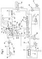
- FIG. 1 The schematic representation of Figure 1 describes a continuously variable transmission generally designated 10 including a torque converter and torque converter clutch 12, a continuously variable transmission (CVT) 14 and a forward/reverse planetary gearset 16 disposed between the torque converter and the CVT 14.
- a continuously variable transmission generally designated 10 including a torque converter and torque converter clutch 12, a continuously variable transmission (CVT) 14 and a forward/reverse planetary gearset 16 disposed between the torque converter and the CVT 14.
- the torque converter 12 is driven by an engine 18 to provide power to the continuously variable transmission 14.
- the planetary gearset 16 includes a sun gear 20, a ring gear 22 and a compound carrier assembly 24.
- the ring gear 22 is groundable through a stationary clutch 26 and the carrier 24 and sun gear 20 are interconnectable through a selectively engageable rotating clutch 28.
- the carrier 24 is drivingly connected with an output shaft 30 of the torque converter and torque converter clutch 12 and the sun gear 20 is connected through a transmission input shaft 32 with an input member or adjustable sheave assembly 34.
- the adjustable sheave assembly 34 is connected with an output member or adjustable sheave assembly 36 by means of a flexible belt member 38.
- the stationary clutch 26 when engaged will provide a reverse drive between the shaft 30 and the sun gear 20 which will cause the continuously variable transmission 14 to operate at a reverse ratio.
- the engagement of the rotating clutch 28 will cause a 1:1 drive between the shaft 30 and the input member 34 thereby causing a forward drive within the transmission.
- the output member 36 is drivingly connected with a final drive gear 40 which in turn is connected with a final drive gear 42.
- the final drive gear 42 is drivingly connected with a conventional differential gearset 44 to provide an output from the continuously variable transmission 14.
- the sheave assemblies 34 and 36 are controlled by hydraulic pressure in chambers 46 and 48, respectively.
- the pressure utilized in the chambers 46 and 48 is controlled by an electro/hydraulic control system which includes a conventional positive displacement pump 50 which delivers fluid pressure to a fluid pressure regulator 52.
- the pressure regulator 52 then establishes the maximum system pressure within the control system and delivers that pressure through a passage 54 to a primary sheave limit valve 56.
- the fluid pressure in passage 54 is limited by a line limit valve 60 when the maximum system pressure is satisfied in passage 54 the regulator valve 52 will distribute fluid pressure to a passage 58 which includes the line limit valve 60 for limiting the pressure within the passage 58 to a predetermined amount.
- the passage 58 communicates with a torque converter clutch control valve 61 and a torque converter clutch valve 62. These two valves operate in a conventional manner and control the pressure and flow of fluid to the torque converter and torque converter clutch assembly 12.
- the assembly 12 In the position shown, the assembly 12 is in the disengaged or clutch released position and all of the power is transmitted hydro-dynamically in a well known manner.
- the torque converter clutch valve 62 When the torque converter clutch valve 62 is shifted through the control pressure operation, the clutch portion of the assembly 12 is engaged and the engine has a direct drive the planetary gear arrangement 16.
- the passage 54 is also connected to a manual valve 66 through a clutch control valve 68 as limited by the valve 60.
- the manual valve 66 is movable by an operator through a lever 70 to a plurality of operating conditions including Park “P”, Reverse “R”, Neutral “N”, Drive “D”, Intermediate “INT” and Low “LO”.
- the lever 70 is manipulated linearly in a slot 72 to the drive positions above enumerated.
- the slot 72 also has a side or adjacent slot 74 which permits the driver to preselect a number of transmission ratios as will be described later.
- the clutch control valve 68 provides the necessary pressure to engage the clutches 28 and 26.
- the pressure distributed by the clutch control valve 68 is controlled by a variable bleed solenoid valve 76 which permits the electronic control system to adjust the engaging and disengaging pressure of the clutches 26 and 28.
- the fluid pressure in passage 54 is connected to a ratio control valve 84 and through a passage 78 to the primary limit valve 56. This valve 56 limits the pressure distributed to the chamber 46.
- An actuator control 80 includes a ratio control motor 82, the ratio control valve 84, and a feedback arm 86 which is connected to a portion of the sheave assembly 34. The arm 86 is connected to the movable sheave of the sheave assembly 34 such that the position of the sheave assembly is always known to the control system.
- the control valve 84 is manipulated such that fluid pressure is increased at the sheave assembly 34 or decreased at the sheave assembly 34. If the fluid pressure is increased at the sheave assembly 34, the ratio within the continuously variable transmission 14 will change from an underdrive ratio shown toward an overdrive position. If the continuously variable transmission 14 is established at an overdrive or above a minimum underdrive ratio and the pressure at the control valve 84 is relieved, the ratio within the continuously variable transmission 14 will move toward an underdrive ratio.
- the pressure output or pressure established by the regulator valve 52 is also variable such that a control function is provided by a pulse width modulated line control valve 88.
- the line control valve 88 has a pulse width modulated solenoid, which is a well known device, and is adapted to deliver a control pressure through a passage 90 to the regulator valve 52.
- the pressure in the passage 90 is increased to cause an increase in the output of pressure regulator 52 and decreased to cause a decrease in line pressure.
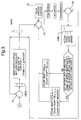
- the ratio within the continuously variable transmission 14 is preferably controlled by a conventional programmable digital computer which is programmed to operate the algorithm shown in Figures 2 and 3. Briefly, the algorithm described in Figures 2 and 3 provides command signals for the continuously variable transmission 14 as received from the operator through the range selector manual valve 66 and from various engine and vehicle speed signals.
- the vehicle provides an engine speed or an input speed to the transmission at a sensor 92 and input speed to the continuously variable transmission 14 at a sensor 94 and an output speed from the continuously variable transmission at a sensor 96.
- the control system can determine if the torque converter clutch is engaged or disengaged and can also determine the actual speed ratio across the continuously variable transmission 14.
- the control system determines a desired speed ratio from the various inputs and establishes an output signal which is directed a summing or comparing unit S1.
- the summing unit S1 compares the desired speed signal as with a commanded speed signal, as will be described in more detail later.
- the commanded speed signal is stored and also fed back to the summing unit S1 for error correction as will be discussed later.
- the commanded signal is also directed to a Table SRAC which effects a count for the motor 82.
- the counts at the motor 82 are equal or comparable with sheave travel.
- the sheave travel is then also related by the curve C1 with the speed ratio of the continuously variable transmission 14.
- the control system by knowing the count at the Table SRAC will establish the commanded speed ratio at the transmission.
- Figure 5 depicts a portion of the actuator 80.
- the ratio control motor 82 is connected with a link 100 which is also connected to a valve spool 102 of the valve 84.
- Feedback link 86 is connected to a hub or rim 104 of the sheave assembly 34.
- the enlarged portion of the valve 84 is shown in Figure 6.
- the motor 82 is a stepper motor which will respond to the counts as output by the algorithm described above.
- the valve 84 includes the valve spool 102 which is slidably disposed in a valve bore 106 and urged leftwardly by a spring 108 to maintain the link 100, the valve spool 102, the stepper motor 82 and feedback link 86 in firm contact.
- the valve bore 106 has a first port 110 which is communicating with the valve 56, a second port 112 which communicates with the chamber 46 and a third port 114 which communicates with exhaust or with the system sump 116.
- the motor 82 When it is desired to move toward an overdrive condition, the motor 82 will receive the proper count input from the algorithm described above such that the valve spool 102 will be moved leftward opening fluid communication between the valve 56 and the chamber 46 to cause the sheave assembly 34 to urge the belt 38 outwardly thereby pulling the belt 38 inwardly in the sheave 36 and accommodating a lesser diameter in sheave 36.
- the hub 104 will be moved rightward thereby causing the link 100 to pivot and bring the valve spool 102 back toward the neutral position shown. In this position, the fluid pressure from valve 56 is maintained at the chamber 46 to accommodate any fluid leakage which might occur downstream.
- valve spool 102 has a central land 118 which is large enough to overlap the port 112.
- the port 112 is essentially line on line with the right edge of land 118 which will permit fluid pressure in port 110 to feed any leakage makeup necessary to maintain the pressure in chamber 46 at the desired level.
- the overlap of land 118 creates a time lag before the pressure within the chamber 46 can be exhausted. This time lapse or lag is compensated by the step count described above in the algorithm.
- the stepper motor 82 When the step count occurs, the stepper motor 82 will rapidly move rightward to accommodate the large increase in count command thereby causing the valve spool 102 to move rightward rapidly, quickly opening the communication between the ports 112 and 114 so that the pressure in chamber 46 can be rapidly reduced. This will permit the continuously variable transmission 14 to change ratios in the underdrive direction quite rapidly. The time required for the count change (to cause the valve to move sufficiently to exhaust the chamber 46) is removed from the control cycle thus eliminating the lag which is otherwise present with the valve overlap.
- the commanded ratio is then directed to a transmission control module TCM driver which in turn directs the signal to the motor 82 for the movement of the actuator 80.
- the actuator 80 adjusts the speed ratio within the continuously variable transmission 14. This signal is then compared at a summing point S2 which compares the actual transmission speed ratio with the commanded transmission speed ratio to determine if an adapt modifier is necessary to bring the control count into accordance with the driver commanded or driver desired count.
- the output of the adapt modifier is directed to a summing unit S3 which adds the commanded signal, the count adapt modifier signal and a valve overlap signal from a valve overlap control C2 to provide a signal to the TCM driver.
- the valve overlap control C2 provides a step count to a transmission control module (TCM DRIVER) which directs the count to the actuator 80. This will cause the control motor 82 to move a predetermined step when the mechanism is shifting in an underdrive direction.
- TCM DRIVER transmission control module
- the Ratio Control Algorithm selects the desired ratio the transmission is to operate in from a series of maps.
- the maps that are used are determined by Transmission Range. Desired ratio determines commanded ratio which is used to set the step count of the ratio control motor.
- the ratio control motor positions the ratio control valve. The current step count of the motor is saved on powerdown and must remain the same on the next powerup. A control flow logic at the end of this section is included. This algorithm runs at 25 milliseconds on a conventional programmable digital computer.
- the desired transmission ratio is selected from Table DTR a function of CVT _ RANGE . It is stored in the process variable DESIRED_SPEED_RATIO. Process Variable DTR Operating Range Granularity DESIRED_SPEED_RATIO 0 to 6.5535 0.0001
- CVT _ RANGE indicates REVERSE
- the desired speed ratio, DESIRED_SPEED_RATIO is defined by the constant KE_REV_DESIRED_SPEED_RATIO.
- Desired Speed Ratio is determined by one of three maps dependent upon the state of the pattern select switch. In Intermediate and Low Range, the same maps are used but Desired Speed Ratio is limited to a maximum value defined in calibration tables. In Park, Neutral, Drive, Intermediate and Low Ranges, Detent Desired Speed Ratio determines the desired speed ratio when in the Detent Mode.
- DESIRED_SPEED_RATIO desired speed ratio
- process variable DESIRED_DET_SPEED_RATIO found in the two-dimensional table KV_DET_DESIRED_SPEED_RATIO (DDSR) plus a signed adaptive speed ratio DET_SPEED_RATIO_ADAPT found in non-volatile RAM table DET_SPEED_RATIO_ADAPT_CELLS (DSRA) .
- DDSR two-dimensional table KV_DET_DESIRED_SPEED_RATIO
- DSRA non-volatile RAM table
- the independent variable in these tables DDSR, DSRA is VEHICLE_SPEED and the dependent variable is DESIRED_DET_SPEED_RATIO and DET_SPEED_RATIO_ADAPT respectively.
- the dependent variable is linearly interpolated, a function of the independent variable (vehicle speed).
- DESIRED_SPEED_RATIO DESIRED_DET_SPEED_RATIO + DET_SPEED_RATIO_ADAPT 2 Dimensional Table DDSR KV_DET_DESIRED_SPEED_RATIO Independent Variable Operating Range Resolution KPH_OUTPUT_SPEED 4 to 228 kph 14 kph Dependent Variable Operating Range Granularity DESIRED_DET_SPEED_RATIO 0 to 6.5535 0.0001 Process Variable Operating Range Granularity DESIRED_DET_SPEED_RATIO 0 to 6.5535 0.0001 DET_SPEED_RATIO_ADAPT -3.2768 to 3.2767 0.0001
- the detent desired ratio is scheduled to maintain a desired engine RPM. Desired engine speed is determined from the calibration KE_DESIRED_DET_ENGINE_RPM.
- desired decent speed ratio is modified by signed adaptive cells DET_SPEED_RATIO_ADAPT_CELLS.
- the independent variable in the table is KPH_OUTPUT_SPEED a nd the dependent variable is DET_SPEED_RATIO_ADAPT. If check sum of the adapt cells fail, then all of the adapt cells must reset to their default values of zero.
- the adaptive cells, DET_SPEED_RATIO_ADAPT_CELLS may be updated when timer, DETENT_ADAPT_TIMER, reaches calibration time KE_DETENT_ADAPT_TIME .
- the timer, DETENT_ADAPT_TIMER is cleared and started when the detent mode is first entered.
- DETENT_ADAPT_TIMER reaches calibration time KE_DETENT_ADAPT_TIME
- the adaptive cells may be updated.
- the timer is also cleared and started after an adapt update which allows time for the actual ratio to move to the desired speed ratio before another adapt update is allowed.
- the actual engine rpm is used in the following equation to determine the engine RPM error, DETENT_ENGINE_RPM_ERROR : DETENT_ENGINE_RPM_ERROR is a signed number.
- DET_SPEED_RATIO_ADAPT_CELLS is updated by the signed modifier DETENT_RATIO_ADAPT_MOD found in table KV_DETENT_ADAPT_MODIFIER .
- the independent variable in the table is DETENT_ENGINE_RPM_ERROR and the dependent variable is DETENT_RATIO_ADAPT_MOD.
- DAM signed modifier
- the closest vehicle speed cell is updated by adding the signed modifier, determined from table KV_DETENT_ADAPT_MODIFIER (DAM) , which has been multiplied by factor KE_DET_ADAPT_FACTOR_0 .
- a percentage of the signed modifier value also updates the two neighbouring table positions on either side of the selected cell (vehicle speed) position.
- the percentage factor is a calibration constant dependent upon cell position.
- factor KE_DET_ADAPT_FACTOR_1L is used on the cell next to the selected cell on the decreasing vehicle speed side.
- the value of DET_SPEED_RATIO_ADAPT_CELLS is bounded by KE_MIN_DET_SPEED_RATIO_ADAPT, and KE_MAX_DET_SPEED_RATIO_ADAPT.
- desired speed ratio is defined by one of three maps in table DXDR dependent upon the pattern select input which sets NORMAL , SPORT or ECONOMY .
- desired speed ratio DESIRED_SPEED_RATIO
- t o DRIVE_NORM_DESIRED_SPEED_RATIO which is found in the three-dimensional table KA_DRIVE_NORM_DESIRED_RATIO (DXDR) .
- desired speed ratio DESIRED_SPEED_RATIO
- DRIVE_SPORT_DESIRED_SPEED_RATIO DRIVE_ECON_DESIRED_SPEED_RATIO
- DXDR KA_DRIVE_ECON_DESIRED_RATIO
- the independent variables in the tables are KPH_OUTPUT_SPEED and THROTTLE , the dependent variables are DRIVE_NORM_DESIRED_SPEED_RATIO , DRIVE_SPORT_DESIRED_SPEED_RATIO and DRIVE_ECON_DESIRED_SPEED_RATIO.
- the desired speed ratio is defined by the DRIVE table and the pattern select, KA_DRIVE_NORM_DESIRED_RATIO, KA_DRIVE_SPORT_DESIRED_RATIO or KA_DRIVE_ECON_DESIRED_RATIO, however, it is limited to a maximum speed ratio.
- the maximum speed ratio in DRIVE_INT is defined in the two-dimensional table KV_INT_DESIRED_SR_LIMIT (IDSL) .
- the maximum speed ratio in DRIVE_LOW is defined in the two-dimensional table KV_LOW_DESIRED_SR_LIMIT (LDSL) .
- the independent variable in the tables is KPH_OUTPUT_SPEED and the dependent variables are INT_DESIRED_SR_LIMIT and LOW_DESIRED_SR_LIMIT .
- DESIRED_SPEED_RATIO is the DRIVE_DESIRED_SPEED_RATIO from Table KA_DRIVE_DESIRED_RATIO or INT_DESIRED_SR_LIMIT from cable KV_INT_DESIRED_SR_LIMIT, which ever table value contains the lowest speed ratio value.
- DESIRED_SPEED_RATIO can be less than INT_DESIRED_SR_LIMIT as defined by DRIVE_DESIRED_SPEED_RATIO but it cannot exceed INT_DESIRED_SR_LIMIT .
- the Driver Commanded Gear Mode (DCG Mode) is entered when the Range is DRIVE and the input DRIVER_COMMAND_GEAR is true.
- DCG Mode the transmission is manually upshifted and downshifted by the driver. There are a maximum of 6 gears, each of which are assigned a speed ratio.
- DCG_SPEED_RATIO is set by DCG_SPEED_RATIO .
- DCG_SPEED_RATIO is found in the calibration table KV_DCG_SPEED_RATIO (DCG) as a function of COMMANDED_GEAR.
- COMMANDED_GEAR is determined by DESIRED_GEAR and calibration limits. Both COMMANDED_GEAR and DESIRED_GEAR are limited to the calibration constant KE_DCG_GEAR_NUMBER which is the maximum number of discrete gear steps available in DCG Mode. The minimum number of gear steps is 1.
- DCG_ERROR_x does not satisfy the above condition, set DESIRED_GEAR equal to the associated gear value of DCG_ERROR_x where DCG_ERROR_x is a negative number closest to zero.
- DCG_MIN_GEAR is set to one and DCG_MAX_GEAR is set to the calibration constant KE_DCG_GEAR_NUMBER which is the maximum number of discrete gear steps available in DCG Mode.
- DESIRED_SPEED_RATIO is determined by the maps described previously.
- DESIRED_GEAR Each time the driver input indicates upshift, DESIRED_GEAR is incremented one step. When the driver input indicates downshift, DESIRED_GEAR is decremented one step. Again DESIRED_GEAR is limited to a maximum found in calibration constant KE_DCG_GEAR_NUMBER and to a minimum of 1. COMMANDED_GEAR is set to DESIRED_GEAR within DCG_MAX_GEAR and DCG_MIN_GEAR limitations.
- a gear display output follows DESIRED_GEAR.
- the gear display and DESIRED_GEAR will temporarily show a driver input even when outside the limits DCG_MAX_GEAR and DCG_MIN_GEAR which is bounded by 1 and KE_DCG_GEAR_NUMBER .
- COMMANDED_GEAR is always limited to a minimum of the value of DCG_MIN_GEAR and a maximum of DCG_MAX_GEAR . If a driver commands a downshift less than DCG_MIN_GEAR or an upshift greater than DCG_MAX_GEAR , DESIRED_GEAR follows the signal for a calibratable amount of time, KE_DESIRED_DISPLAY_TIME.
- DCG_MAX_GEAR When DCG_MAX_GEAR is set due to one of the above calibrations, the value of DCG_MAX_GEAR is incremented when vehicle speed is equal to or above the calibration plus KE_DCG_MAX_DELTA . For example, if in the kickdown mode and vehicle speed is less than KE_DCG_DETENT_43 , DCG_MAX_GEAR is set to 3. When vehicle speed is greater than or equal to KE_DCG_DETENT_43 plus KE_DCG_MAX_DELTA , DCG_MAX_GEAR is then set to 4. With DCG_MAX_GEAR set to 4, a driver initiated upshift will allow DESIRED_GEAR and COMMANDED_GEAR to equal 4.
- DCG_MIN_GEAR When DCG_MIN_GEAR is set due to one of the above calibrations, the value of DCG_MIN_GEAR is decremented (minimum of 1) when vehicle speed is less than the calibration minus KE_DCG_OVERSPD_DELTA . For example, if vehicle speed is greater than KE_DCG_OVERSPD_12 , DCG_MIN_GEAR is set to 2. When vehicle speed is less than KE_DCG_OVERSPD_12 minus KE_DCG_OVERSPD_DELTA , then DCG_MIN_GEAR is set to 1. With DCG_MIN_GEAR set to 1, a driver initiated downshift will allow DESIRED_GEAR and COMMANDED_GEAR to equal 1.
- Commanded speed ratio is determined from the error between desired speed ratio and the last commanded speed ratio. This error is used to determine the rate at which commanded speed ratio converges to desired speed ratio. The commanded speed ratio is used to look up the count of the ratio control actuator. Commanded speed ratio calculation is frozen if vehicle speed is less than KE_RATIO_CONTROL_FREEZE_LOW_VS because speed signals are noisy at the low vehicle speeds of approximately three (3) kph.
- COMMANDED_SR_ERROR DESIRED_SPEED_RATIO - COMMANDED_SPEED_RATIO Table
- KV_COM_ERROR_SR_RATE (CESR) modifies the last COMMANDED_SPEED_RATIO .
- KV_COM_ERROR_SR_RATE is a two-dimensional tables with COMMANDED_SR_ERROR as the independent variable and DELTA_COM_SR_PER_SEC the dependent variable.
- DELTA_COM_SR_PER_SEC is multiplied by the loop time to give DELTA_COM_SR_PER_LOOP.
- the driven position of the ratio control actuator is stored in counts.
- the controller keeps track of the counts in process variable COUNT saving the value at powerdown.
- the actual count follows COMMANDED_COUNT as rapidly as pulses can occur. If COUNT check sum has been compromised, then COUNT is reset to KE_RATIO_MOTOR_DEFAULT_COUNT.
- COMMANDED_COUNT is determined by looking up the base actuator count, ACTUATOR_COUNT , which is then modified by an adapt value COUNT_ADAPT_CELL and an underdrive step count if conditions permit.
- COMMANDED_COUNT ACTUATOR_COUNT + COUNT_ADAPT_CELL
- COUNT the actual position of ratio control actuator
- the base actuator count, ACTUATOR_COUNT is found in table KV_SR_ACTUATOR_COUNT (SRAC) .
- the independent variable in table KV_SR_ACTUATOR_COUNT is COMMANDED_SPEED_RATIO , the dependent variable is ACTUATOR_COUNT .
- a signed step value is added each loop to the commanded count in order to quickly position the ratio control valve in an exhaust position (due to valve overlap). The step is not added when desired and commanded speed ratio are close to equal.
- commanded speed ratio error COMMANDED_SR_ERROR
- KE_STEP_COUNT_VALUE is added to ACTUATOR_COUNT and process variable flag STEP_COUNT_ADDED is set.
- COMMANDED_SR_ERROR When commanded speed ratio error, COMMANDED_SR_ERROR , becomes greater than the signed value of KE_SR_ERROR_COUNT_CLEAR while process variable STEP_COUNT_ADDED is set , KE_STEP_COUNT_VALUE is not longer used in determining COMMANDED_COUNT and process variable STEP_COUNT_ADDED is cleared.
- COMMANDED_COUNT ACTUATOR_COUNT + COUNT_ADAPT_CELL Calibration Constant Operating Range Granularity KE_SR_ERROR_COUNT_ADD -3.2768 to 3.2767 0.0001 KE_SR_ERROR_COUNT_CLEAR -3.2768 to 3.2767 0.0001 KE_STEP_COUNT_VALUE -128 to 127 1 Process Variable Operating Range Granularity STEP_COUNT_ADDED 0 to 255 1
- Step Count Adapt system is in place to adjust for offsets when actual ratio does not match commanded ratio.
- An offset can occur if the actuator does not move upon a count change or if an offset exists in the primary pulley link.
- Actuator step count adapt cell is kept in non-volatile ram, if its check sum has been compromised, then it gets reset to zero.
- Actuator step count adapt cell, COUNT_ADAPT_CELL calculation is frozen if vehicle speed is less than KE_RATIO_CONTROL_FREEZE_LOW_VS because speed signals are noisy and unreliable at the low vehicle speeds.
- ACTUAL_SPEED_RATIO_ERROR COMMANDED_SPEED_RATIO - CVT_SPEED_RATIO
- the adaptive cell, COUNT_ADAPT_CELL may be updated when timer, COUNT_ADAPT_TIMER , reaches calibration time KE_COUNT_ADAPT_TIME .
- the timer, COUNT_ADAPT_TIMER is cleared and started when COMMANDED_SR_ERROR is greater than or equal to KE_COUNT_ADAPT_LOW and less than KE_COUNT_ADAPT_HIGH .
- the timer is incremented as long as commanded speed ratio error, COMMANDED_SR_ERROR , is within the calibration band and it is stopped if it falls out side the band.
- Timer COUNT_ADAPT_TIMER is cleared and started when COMMANDED_SR_ERROR again is within the calibration band.
- the adaptive cell may be updated.
- the timer is also cleared and started after an adapt update which allows time for the actual ratio to move to the desired speed ratio before another adapt updated is allowed.
- ACTUAL_SPEED_RATIO_ERROR is a signed number.
- COUNT_ADAPT_CELL is updated by the signed modifier COUNT_ADAPT_MOD found in table KV_COUNT_ADAPT_MODIFIER (CAM) .
- the independent variable in the table is ACTUAL_SPEED_RATIO_ERROR and the dependent variable is COUNT_ADAPT_MOD .
- COUNT_ADAPT_CELL x COUNT_ADAPT_CELL x-1 + COUNT_ADAPT_MOD NV RAM Operating Range Granularity COUNT_ADAPT_CELL -20,000 to 20,000 1 2 Dimensional Table CAM KV_COUNT_ADAPT_MODIFIER Independent Variable Operating Range Resolution ACTUAL_SPEED_RATIO_ERROR -0.200 to 0.200 0.025 Dependent Variable Operating Range Granularity COUNT_ADAPT_MOD -128 to 127 1 Calibration Constant Operating Range Granularity KE_COUNT_ADAPT_TIME 0 to 6.375 sec 0.025 sec KE_COUNT_ADAPT_LOW -3.2768 to 3.2767 0.0001 KE_COUNT_ADAPT_HIGH -3.2768 to 3.2767 0.0001 Process Variable Operating Range Granularity ACTUAL_SPEED_RATIO_ERROR -3.2768 to 3.2767 0.0001 COUNT_ADAPT_MOD
- process variables listed below need slew capability through instrumentation.
- the process variables will use the normal algorithm (a slew value that is present prior to power down is not saved and will be cleared for the next power up).
- the actual process variable in use, whether calculated or slewed, must be displayed when viewing the process variable with instrumentation.
- the process variable DESIRED_SPEED_RATIO must be able to be slewed which will override the normal ratio determination.
- the process variable COMMANDED_COUNT must be able to be slewed which will override the normal commanded count determination.
- the DCG Mode can be enabled by the manual modifier V_DCG_MODE_ MAN . If V_DCG_MODE_MAN is equal to 0, then the DCG Mode is entered or exited by the state of DRIVER_COMMAND_GEAR . If V_DCG_MODE_ MAN is anything other than 0, the DCG Mode is enabled.
- COMMANDED_GEAR must be able to be slewed when in the DCG Mode (either by the switch or the manual modifier), which will override the normal desired gear determination.
- COMMANDED_GEAR is limited to a maximum found in calibration constant KE_DCG_GEAR_NUMBER and to a minimum of 1 but is not restricted by DCG_MAX_GEAR and DCG_MIN_GEAR limitations.
- COUNT_ADAPT_CELL must be able to be slewed which will override the normal adapt determination.
- the non-volatile ram value of COUNT_ADAPT_CELL must also be able to be initialized to value found in V_COUNT_ADAPT_MAN .
Abstract
Description
- This invention relates to a continuously variable transmission and controls.
- Continuously variable ratio transmissions are employed in vehicles to provide efficient drive systems. The transmission ratio can be changed in a continuous manner from a maximum underdrive ratio to a maximum overdrive ratio. This permits the engine to be operated at either the best fuel consumption area or the best performance area. Vehicle speed can be maintained at a substantially constant level while the transmission ratio is varied to attain a desired vehicle speed as requested by an operator.
- The most currently used continuously variable transmissions are the flexible belt type due mainly to the advent of the flexible steel belt which runs against steel sheaves. The sheaves of the input and output pulleys are movable axially to adjust the radius at which the belt turns. The sheaves are moved to hydraulic pressure which is distributed from a control valve.
- It is an object of this invention to provide an improved control for a continuously variable transmission of the flexible belt type.
- In one aspect of this invention, a stepper motor and a control valve are provided to control the speed ratio between an input member and an output member of a flexible belt type continuously variable transmission.
- In another aspect of this invention, the stepper motor receives a count signal from the control to establish the commanded position and a speed ratio of the continuously variable transmission through movement of the control valve.
- In yet another aspect of this invention, the stepper motor is given a step count to rapidly move the valve to permit a ratio change in an underdrive direction.
-
- Figure 1 is a schematic representation of a continuously variable transmission and electro-hydraulic controls therefore.
- Figure 2 is a portion of an algorithm which controls the speed ratio within the continuously variable transmission.
- Figure 3 is another portion of the algorithm which controls the speed ratio within the continuously variable transmission.
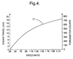
- Figure 4, is a graph representing the relation between speed ratio and sheave travel and Forcemotor Counts.
- Figure 5 is a diagrammatic representation of a portion of the hydraulic control for a continuously variable transmission.
- Figure 6 is an enlarged view of the hydraulic control shown in Figure 5.
-
- The schematic representation of Figure 1 describes a continuously variable transmission generally designated 10 including a torque converter and
torque converter clutch 12, a continuously variable transmission (CVT) 14 and a forward/reverseplanetary gearset 16 disposed between the torque converter and theCVT 14. - The
torque converter 12 is driven by anengine 18 to provide power to the continuouslyvariable transmission 14. Theplanetary gearset 16 includes asun gear 20, aring gear 22 and acompound carrier assembly 24. Thering gear 22 is groundable through astationary clutch 26 and thecarrier 24 andsun gear 20 are interconnectable through a selectively engageable rotatingclutch 28. - The
carrier 24 is drivingly connected with anoutput shaft 30 of the torque converter andtorque converter clutch 12 and thesun gear 20 is connected through atransmission input shaft 32 with an input member oradjustable sheave assembly 34. Theadjustable sheave assembly 34 is connected with an output member oradjustable sheave assembly 36 by means of aflexible belt member 38. These types of devices are well known in the art such that a more elaborate description is not believed necessary for those skilled in the art. - The
stationary clutch 26 when engaged will provide a reverse drive between theshaft 30 and thesun gear 20 which will cause the continuouslyvariable transmission 14 to operate at a reverse ratio. The engagement of the rotatingclutch 28 will cause a 1:1 drive between theshaft 30 and theinput member 34 thereby causing a forward drive within the transmission. - The
output member 36 is drivingly connected with afinal drive gear 40 which in turn is connected with afinal drive gear 42. Thefinal drive gear 42 is drivingly connected with a conventionaldifferential gearset 44 to provide an output from the continuouslyvariable transmission 14. - The sheave assemblies 34 and 36 are controlled by hydraulic pressure in
chambers chambers positive displacement pump 50 which delivers fluid pressure to afluid pressure regulator 52. Thepressure regulator 52 then establishes the maximum system pressure within the control system and delivers that pressure through apassage 54 to a primarysheave limit valve 56. - The fluid pressure in
passage 54 is limited by aline limit valve 60 when the maximum system pressure is satisfied inpassage 54 theregulator valve 52 will distribute fluid pressure to apassage 58 which includes theline limit valve 60 for limiting the pressure within thepassage 58 to a predetermined amount. Thepassage 58 communicates with a torque converterclutch control valve 61 and a torqueconverter clutch valve 62. These two valves operate in a conventional manner and control the pressure and flow of fluid to the torque converter and torqueconverter clutch assembly 12. - In the position shown, the
assembly 12 is in the disengaged or clutch released position and all of the power is transmitted hydro-dynamically in a well known manner. When the torqueconverter clutch valve 62 is shifted through the control pressure operation, the clutch portion of theassembly 12 is engaged and the engine has a direct drive theplanetary gear arrangement 16. - The
passage 54 is also connected to amanual valve 66 through aclutch control valve 68 as limited by thevalve 60. Themanual valve 66 is movable by an operator through alever 70 to a plurality of operating conditions including Park "P", Reverse "R", Neutral "N", Drive "D", Intermediate "INT" and Low "LO". Thelever 70 is manipulated linearly in aslot 72 to the drive positions above enumerated. Theslot 72 also has a side or adjacent slot 74 which permits the driver to preselect a number of transmission ratios as will be described later. - The
clutch control valve 68 provides the necessary pressure to engage theclutches clutch control valve 68 is controlled by a variable bleedsolenoid valve 76 which permits the electronic control system to adjust the engaging and disengaging pressure of theclutches - The fluid pressure in
passage 54 is connected to aratio control valve 84 and through apassage 78 to theprimary limit valve 56. Thisvalve 56 limits the pressure distributed to thechamber 46. Anactuator control 80 includes aratio control motor 82, theratio control valve 84, and afeedback arm 86 which is connected to a portion of thesheave assembly 34. Thearm 86 is connected to the movable sheave of thesheave assembly 34 such that the position of the sheave assembly is always known to the control system. - When the
control motor 82 is actuated as will be described later, thecontrol valve 84 is manipulated such that fluid pressure is increased at thesheave assembly 34 or decreased at thesheave assembly 34. If the fluid pressure is increased at thesheave assembly 34, the ratio within the continuouslyvariable transmission 14 will change from an underdrive ratio shown toward an overdrive position. If the continuouslyvariable transmission 14 is established at an overdrive or above a minimum underdrive ratio and the pressure at thecontrol valve 84 is relieved, the ratio within the continuouslyvariable transmission 14 will move toward an underdrive ratio. - The pressure output or pressure established by the
regulator valve 52 is also variable such that a control function is provided by a pulse width modulatedline control valve 88. Theline control valve 88 has a pulse width modulated solenoid, which is a well known device, and is adapted to deliver a control pressure through apassage 90 to theregulator valve 52. The pressure in thepassage 90 is increased to cause an increase in the output ofpressure regulator 52 and decreased to cause a decrease in line pressure. - The ratio within the continuously
variable transmission 14 is preferably controlled by a conventional programmable digital computer which is programmed to operate the algorithm shown in Figures 2 and 3. Briefly, the algorithm described in Figures 2 and 3 provides command signals for the continuouslyvariable transmission 14 as received from the operator through the range selectormanual valve 66 and from various engine and vehicle speed signals. - The vehicle provides an engine speed or an input speed to the transmission at a
sensor 92 and input speed to the continuouslyvariable transmission 14 at asensor 94 and an output speed from the continuously variable transmission at asensor 96. By comparing these various speed signals, the control system can determine if the torque converter clutch is engaged or disengaged and can also determine the actual speed ratio across the continuouslyvariable transmission 14. - The control system determines a desired speed ratio from the various inputs and establishes an output signal which is directed a summing or comparing unit S1. The summing unit S1 compares the desired speed signal as with a commanded speed signal, as will be described in more detail later. The commanded speed signal is stored and also fed back to the summing unit S1 for error correction as will be discussed later. The commanded signal is also directed to a Table SRAC which effects a count for the
motor 82. - As seen in Figure 4, the counts at the
motor 82 are equal or comparable with sheave travel. The sheave travel is then also related by the curve C1 with the speed ratio of the continuouslyvariable transmission 14. Thus, the control system, by knowing the count at the Table SRAC will establish the commanded speed ratio at the transmission. - Figure 5 depicts a portion of the
actuator 80. As can be seen, theratio control motor 82 is connected with alink 100 which is also connected to avalve spool 102 of thevalve 84.Feedback link 86 is connected to a hub or rim 104 of thesheave assembly 34. The enlarged portion of thevalve 84 is shown in Figure 6. - The
motor 82 is a stepper motor which will respond to the counts as output by the algorithm described above. Thevalve 84 includes thevalve spool 102 which is slidably disposed in avalve bore 106 and urged leftwardly by aspring 108 to maintain thelink 100, thevalve spool 102, thestepper motor 82 and feedback link 86 in firm contact. The valve bore 106 has afirst port 110 which is communicating with thevalve 56, asecond port 112 which communicates with thechamber 46 and athird port 114 which communicates with exhaust or with thesystem sump 116. - When it is desired to move toward an overdrive condition, the
motor 82 will receive the proper count input from the algorithm described above such that thevalve spool 102 will be moved leftward opening fluid communication between thevalve 56 and thechamber 46 to cause thesheave assembly 34 to urge thebelt 38 outwardly thereby pulling thebelt 38 inwardly in thesheave 36 and accommodating a lesser diameter insheave 36. - As the
sheave assembly 34 is adjusted, thehub 104 will be moved rightward thereby causing thelink 100 to pivot and bring thevalve spool 102 back toward the neutral position shown. In this position, the fluid pressure fromvalve 56 is maintained at thechamber 46 to accommodate any fluid leakage which might occur downstream. - As best seen in Figure 6, the
valve spool 102 has acentral land 118 which is large enough to overlap theport 112. As seen in Figure 6, theport 112 is essentially line on line with the right edge ofland 118 which will permit fluid pressure inport 110 to feed any leakage makeup necessary to maintain the pressure inchamber 46 at the desired level. However, when it is desired to change the ratio of the continuouslyvariable transmission 14 in an underdrive direction, the overlap ofland 118 creates a time lag before the pressure within thechamber 46 can be exhausted. This time lapse or lag is compensated by the step count described above in the algorithm. - When the step count occurs, the
stepper motor 82 will rapidly move rightward to accommodate the large increase in count command thereby causing thevalve spool 102 to move rightward rapidly, quickly opening the communication between theports chamber 46 can be rapidly reduced. This will permit the continuouslyvariable transmission 14 to change ratios in the underdrive direction quite rapidly. The time required for the count change (to cause the valve to move sufficiently to exhaust the chamber 46) is removed from the control cycle thus eliminating the lag which is otherwise present with the valve overlap. - The commanded ratio is then directed to a transmission control module TCM driver which in turn directs the signal to the
motor 82 for the movement of theactuator 80. Theactuator 80, as described above, adjusts the speed ratio within the continuouslyvariable transmission 14. This signal is then compared at a summing point S2 which compares the actual transmission speed ratio with the commanded transmission speed ratio to determine if an adapt modifier is necessary to bring the control count into accordance with the driver commanded or driver desired count. - The output of the adapt modifier is directed to a summing unit S3 which adds the commanded signal, the count adapt modifier signal and a valve overlap signal from a valve overlap control C2 to provide a signal to the TCM driver. The valve overlap control C2, provides a step count to a transmission control module (TCM DRIVER) which directs the count to the
actuator 80. This will cause thecontrol motor 82 to move a predetermined step when the mechanism is shifting in an underdrive direction. - The Ratio Control Algorithm selects the desired ratio the transmission is to operate in from a series of maps. The maps that are used are determined by Transmission Range. Desired ratio determines commanded ratio which is used to set the step count of the ratio control motor. The ratio control motor positions the ratio control valve. The current step count of the motor is saved on powerdown and must remain the same on the next powerup. A control flow logic at the end of this section is included. This algorithm runs at 25 milliseconds on a conventional programmable digital computer.
- The desired transmission ratio is selected from Table DTR a function of CVT_RANGE. It is stored in the process variable DESIRED_SPEED_RATIO.
Process Variable DTR Operating Range Granularity DESIRED_SPEED_RATIO 0 to 6.5535 0.0001 - If CVT_RANGE indicates REVERSE, the desired speed ratio, DESIRED_SPEED_RATIO is defined by the constant KE_REV_DESIRED_SPEED_RATIO.
Calibration Constant Operating Range Granularity KE_REV_DESIRED_SPEED_RATIO 0 to 6.5535 0.0001 - In Park, Neutral and Drive Range, Desired Speed Ratio is determined by one of three maps dependent upon the state of the pattern select switch. In Intermediate and Low Range, the same maps are used but Desired Speed Ratio is limited to a maximum value defined in calibration tables. In Park, Neutral, Drive, Intermediate and Low Ranges, Detent Desired Speed Ratio determines the desired speed ratio when in the Detent Mode.
- When THROTTLE_KICKDOWN is requested by the operator, the detent mode is active and desired speed ratio, DESIRED_SPEED_RATIO, is defined by process variable DESIRED_DET_SPEED_RATIO found in the two-dimensional table KV_DET_DESIRED_SPEED_RATIO (DDSR) plus a signed adaptive speed ratio DET_SPEED_RATIO_ADAPT found in non-volatile RAM table DET_SPEED_RATIO_ADAPT_CELLS (DSRA). The independent variable in these tables DDSR, DSRA is VEHICLE_SPEED and the dependent variable is DESIRED_DET_SPEED_RATIO and DET_SPEED_RATIO_ADAPT respectively. As in all tables, the dependent variable (desired speed ratio) is linearly interpolated, a function of the independent variable (vehicle speed).
DET_SPEED_RATIO_ADAPT 2 Dimensional Table DDSR
KV_DET_DESIRED_SPEED_RATIOIndependent Variable Operating Range Resolution KPH_OUTPUT_SPEED 4 to 228 kph 14 kph Dependent Variable Operating Range Granularity DESIRED_DET_SPEED_RATIO 0 to 6.5535 0.0001 Process Variable Operating Range Granularity DESIRED_DET_SPEED_RATIO 0 to 6.5535 0.0001 DET_SPEED_RATIO_ADAPT -3.2768 to 3.2767 0.0001 Calibration Constant Operating Range Granularity KE_DESIRED_DET_ENGINE_RPM 0 to 8192 rpm 0.25 rpm - As previously described, when in the decent mode, desired decent speed ratio is modified by signed adaptive cells
DET_SPEED_RATIO_ADAPT_CELLS. The independent variable in the table is KPH_OUTPUT_SPEED and the dependent variable is
DET_SPEED_RATIO_ADAPT. If check sum of the adapt cells fail, then all of the adapt cells must reset to their default values of zero.2 Dimensional Table NV RAM DSRA
DET_SPEED_RATIO_ADAPT_CELLSIndependent Variable Operating Range Resolution KPH_OUTPUT_SPEED 4 to 228 kph 14 kph Dependent Variable Operating Range Granularity DET_SPEED_RATIO_ADAPT -3.2768 to 3.2767 0.0001
KE_DETENT_ADAPT_TIME. The timer, DETENT_ADAPT_TIMER is cleared and started when the detent mode is first entered. It is incremented as long as the decent mode is present and it is stopped when the Detent Mode is exited. When timer, DETENT_ADAPT_TIMER, reaches calibration time
KE_DETENT_ADAPT_TIME, the adaptive cells may be updated. The timer is also cleared and started after an adapt update which allows time for the actual ratio to move to the desired speed ratio before another adapt update is allowed. The actual engine rpm is used in the following equation to determine the engine RPM error, DETENT_ENGINE_RPM_ERROR:DETENT_ENGINE_RPM_ERROR is a signed number.
DET_SPEED_RATIO_ADAPT_CELLS is updated by the signed modifier
DETENT_RATIO_ADAPT_MOD found in table
KV_DETENT_ADAPT_MODIFIER. The independent variable in the table is
DETENT_ENGINE_RPM_ERROR and the dependent variable is
DETENT_RATIO_ADAPT_MOD. When conditions are met to allow an adapt update, the closest vehicle speed cell is updated by adding the signed modifier, determined from table KV_DETENT_ADAPT_MODIFIER (DAM), which has been multiplied by factor KE_DET_ADAPT_FACTOR_0. A percentage of the signed modifier value also updates the two neighbouring table positions on either side of the selected cell (vehicle speed) position. The percentage factor is a calibration constant dependent upon cell position. For example, factor
KE_DET_ADAPT_FACTOR_1L is used on the cell next to the selected cell on the decreasing vehicle speed side. The value of
DET_SPEED_RATIO_ADAPT_CELLS is bounded by
KE_MIN_DET_SPEED_RATIO_ADAPT, and
KE_MAX_DET_SPEED_RATIO_ADAPT.
2 Dimensional Table DAM
KV_DETENT_ADAPT_MODIFIERIndependent Variable Operating Range Resolution DETENT_ENGINE_RPM_ERROR -400 to 400 rpm 50 rpm Dependent Variable Operating Range Granularity DETENT_RATIO_ADAPT_MOD -3.2768 to 3.2767 0.0001 Calibration Constant Operating Range Granularity KE_DETENT_ADAPT_TIME 0 to 6.375 sec 0.025 sec KE_DET_ADAPT_FACTOR_2L 0 to 1 0.0039 KE_DET_ADAPT_FACTOR_1L 0 to 1 0.0039 KE_DET_ADAPT_FACTOR_0 0 to 1 0.0039 KE_DET_ADAPT_FACTOR_1H 0 to 1 0.0039 KE_DET_ADAPT_FACTOR_2H 0 to 1 0.0039 KE_MIN_DET_SPEED_RATIO_ADAPT -3.2768 to 3.2767 0.0001 KE_MAX_DET_SPEED_RATIO_ADAPT -3.2768 to 3.2767 0.0001 Process Variable Operating Range Granularity DETENT_TIMER 0 to 6.375 sec 0.025 sec DETENT_ENGINE_RPM_ERROR -1000 to 1000 rpm 0.25 rpm DETENT_RATIO_ADAPT_MOD -3.2768 to 3.2767 0.0001 - If CVT_RANGE indicates DRIVE or PARK or NEUTRAL, desired speed ratio is defined by one of three maps in table DXDR dependent upon the pattern select input which sets NORMAL, SPORT or ECONOMY. When the pattern select is NORMAL, desired speed ratio, DESIRED_SPEED_RATIO, is equal to DRIVE_NORM_DESIRED_SPEED_RATIO which is found in the three-dimensional table KA_DRIVE_NORM_DESIRED_RATIO (DXDR). When the pattern select is SPORT or ECONOMY, desired speed ratio,
DESIRED_SPEED_RATIO, is equal to
DRIVE_SPORT_DESIRED_SPEED_RATIO or
DRIVE_ECON_DESIRED_SPEED_RATIO, which are found in the three-dimensional table KA_DRIVE_SPORT_DESIRED_RATIO DXDR or KA_DRIVE_ECON_DESIRED_RATIO (DXDR). The independent variables in the tables are KPH_OUTPUT_SPEED and THROTTLE, the dependent variables are DRIVE_NORM_DESIRED_SPEED_RATIO,
DRIVE_SPORT_DESIRED_SPEED_RATIO and
DRIVE_ECON_DESIRED_SPEED_RATIO.3 Dimensional Table DXDR
KA_DRIVE_NORM_DESIRED_RATIO,
KA_DRIVE_SPORT_DESIRED_RATIO,
KA_DRIVE_ECON_DESIRED_RATIOIndependent Variable Operating Range Resolution THROTTLE 0 to 100 % 6.25% KPH_OUTPUT_SPEED 4 to 228 kph 14 kph Dependent Variable Operating Range Granularity DRIVE_NORM_DESIRED_SPEED_RATIO 0 to 6.5535 0.0001 DRIVE_SPORT_DESIRED_SPEED_RATIO DRIVE_ECON_DESIRED_SPEED_RATIO Process Variable Operating Range Granularit DRIVE_NORM_DESIRED_SPEED_RATIO 0 to 6.5535 0.0001 DRIVE_SPORT_DESIRED_SPEED_RATIO 0 to 6.5535 0.0001 DRIVE_ECON_DESIRED_SPEED_RATIO 0 to 6.5535 0.0001 - If CVT_RANGE indicates DRIVE_INT or DRIVE_LOW, the desired speed ratio is defined by the DRIVE table and the pattern select,
KA_DRIVE_NORM_DESIRED_RATIO,
KA_DRIVE_SPORT_DESIRED_RATIO or
KA_DRIVE_ECON_DESIRED_RATIO, however, it is limited to a maximum speed ratio. The maximum speed ratio in DRIVE_INT is defined in the two-dimensional table KV_INT_DESIRED_SR_LIMIT (IDSL). The maximum speed ratio in DRIVE_LOW is defined in the two-dimensional table KV_LOW_DESIRED_SR_LIMIT (LDSL). The independent variable in the tables is KPH_OUTPUT_SPEED and the dependent variables are INT_DESIRED_SR_LIMIT and LOW_DESIRED_SR_LIMIT. - For example, in DRIVE_INT, DESIRED_SPEED_RATIO is the DRIVE_DESIRED_SPEED_RATIO from Table
KA_DRIVE_DESIRED_RATIO or INT_DESIRED_SR_LIMIT from cable KV_INT_DESIRED_SR_LIMIT, which ever table value contains the lowest speed ratio value. DESIRED_SPEED_RATIO can be less than
INT_DESIRED_SR_LIMIT as defined by DRIVE_DESIRED_SPEED_RATIO but it cannot exceed INT_DESIRED_SR_LIMIT.2 Dimensional Tables IDSL, LDSL
KV_INT_DESIRED_SR_LIMIT, KV_LOW_DESIRED_SR_LIMITIndependent Variable Operating Range Resolution KPH_OUTPUT_SPEED 4 to 228 kph 14 kph Dependent Variable Operating Range Granularity INT_DESIRED_SR_LIMIT 0 to 6.5535 0.0001 LOW_DESIRED_SR_LIMIT Process Variable Operating Range Granularity INT_DESIRED_SR_LIMIT 0 to 6.5535 0.0001 LOW_DESIRED_SR_LIMIT 0 to 6.5535 0.0001 - The Driver Commanded Gear Mode (DCG Mode) is entered when the Range is DRIVE and the input DRIVER_COMMAND_GEAR is true. In the DCG Mode the transmission is manually upshifted and downshifted by the driver. There are a maximum of 6 gears, each of which are assigned a speed ratio.
- In the DCG Mode, DESIRED_SPEED_RATIO is set by DCG_SPEED_RATIO. DCG_SPEED_RATIO is found in the calibration table KV_DCG_SPEED_RATIO (DCG) as a function of COMMANDED_GEAR. COMMANDED_GEAR is determined by DESIRED_GEAR and calibration limits. Both COMMANDED_GEAR and DESIRED_GEAR are limited to the calibration constant KE_DCG_GEAR_NUMBER which is the maximum number of discrete gear steps available in DCG Mode. The minimum number of gear steps is 1.
2 Dimensional Table DCG
KV_DCG_SPEED_RATIOIndependent Variable Operating Range Resolution COMMANDED_GEAR 1 to 6 1 Dependent Variable Operating Range Granularity DCG_SPEED_RATIO 0 to 6.5535 0.0001 Process Variable Operating Range Granularity DCG_SPEED_RATIO 0 to 6.5535 0.0001 COMMANDED_GEAR 1 to 6 1 DESIRED_GEAR 1 to 6 1 Calibration Constant Operating Range Granularity KE_DCG_GEAR_NUMBER 1 to 6 1 - When the DCG Mode is first entered, the current ACTUAL_SPEED_RATIO is compared to each DCG_SPEED_RATIO found in the table KV_DCG_SPEED RATIO. DCG_ERROR_x (where x = 1,2,3,4,5,6) is equal to DCG_SPEED_RATIO_x minus COMMANDED_SPEED_RATIO. If DCG_ERROR_x is zero or less than KE_DCG_ERROR_LIMIT for a calibration, set DESIRED_GEAR equal to the associated value. If DCG_ERROR_x does not satisfy the above condition, set DESIRED_GEAR equal to the associated gear value of DCG_ERROR_x where DCG_ERROR_x is a negative number closest to zero. When entering DCG Mode, DCG_MIN_GEAR is set to one and DCG_MAX_GEAR is set to the calibration constant KE_DCG_GEAR_NUMBER which is the maximum number of discrete gear steps available in DCG Mode.
Process Variable Operating Range Granularity DCG_ERROR_x -3.2768 to 3.2767 0.0001 DCG_MIN_GEAR 1 to 6 1 DCG_MAX_GEAR 1 to 6 1 Calibration Constant Operating Range Granularity KE_DCG_ERROR_LIMIT 0 to 6.5535 0.0001 - When exiting DCG Mode, DESIRED_SPEED_RATIO is determined by the maps described previously.
- Each time the driver input indicates upshift, DESIRED_GEAR is incremented one step. When the driver input indicates downshift, DESIRED_GEAR is decremented one step. Again DESIRED_GEAR is limited to a maximum found in calibration constant KE_DCG_GEAR_NUMBER and to a minimum of 1. COMMANDED_GEAR is set to DESIRED_GEAR within DCG_MAX_GEAR and DCG_MIN_GEAR limitations.
- A gear display output, not shown, follows DESIRED_GEAR. The gear display and DESIRED_GEAR will temporarily show a driver input even when outside the limits DCG_MAX_GEAR and DCG_MIN_GEAR which is bounded by 1 and KE_DCG_GEAR_NUMBER. COMMANDED_GEAR is always limited to a minimum of the value of DCG_MIN_GEAR and a maximum of DCG_MAX_GEAR. If a driver commands a downshift less than DCG_MIN_GEAR or an upshift greater than DCG_MAX_GEAR, DESIRED_GEAR follows the signal for a calibratable amount of time, KE_DESIRED_DISPLAY_TIME. When a driver commands a downshift less than DCG_MIN_GEAR or an upshift greater than DCG_MAX_GEAR, timer, DCG_DISPLAY_TIMER is initialized and started. Once the timer is complete, DESIRED_GEAR is again limited by DCG_MIN_GEAR. If another driver command occurs outside the limit before the timer is complete, the DESIRED_GEAR is decremented or incremented again and the timer restarted. If DCG_MIN_GEAR or DCG_MAX_GEAR changes due to the gear limit calibrations (not a driver initiated shift), DESIRED_GEAR and COMMANDED_GEAR are immediately bounded by these limits and the timer is not used.
Calibration Constant Operating Range Granularity KE_DESIRED_DISPLAY_TIME 0 to 6.375 sec 0.025 sec Process Variable Operating Range Granularity DCG_DISPLAY_TIMER 0 to 6.375 sec 0.025 sec - During a deceleration (not in detent/kickdown mode), downshifting will occur automatically at the vehicle speeds found in calibration constants KE_DCG_DOWNSHIFT_65,
KE_DCG_DOWNSHIFT_54, KE_DCG_DOWNSHIFT_43,
KE_DCG_DOWNSHIFT_32, KE_DCG_DOWNSHIFT_21. These calibrations set DCG_MAX_GEAR when not in kickdown mode to a gear value which limits COMMANDED_GEAR and DESIRED_GEAR. For example if the vehicle speed is less than KE_DCG_DOWNSHIFT_65, DCG_MAX_GEAR is set to 5. In the detent/kickdown mode, downshifting will occur automatically below the vehicle speeds found in calibration constants KE_DCG_DETENT_65, KE_DCG_DETENT_54, KE_DCG_DETENT_43, KE_DEG_DETENT_32, KE_DCG_DETENT_21. These calibrations set DCG_MAX_GEAR in detent/kickdown mode to a gear value which limits COMMANDED_GEAR and DESIRED_GEAR. When DCG_MAX_GEAR is set due to one of the above calibrations, the value of DCG_MAX_GEAR is incremented when vehicle speed is equal to or above the calibration plus KE_DCG_MAX_DELTA. For example, if in the kickdown mode and vehicle speed is less than KE_DCG_DETENT_43, DCG_MAX_GEAR is set to 3. When vehicle speed is greater than or equal to KE_DCG_DETENT_43 plus KE_DCG_MAX_DELTA, DCG_MAX_GEAR is then set to 4. With DCG_MAX_GEAR set to 4, a driver initiated upshift will allow DESIRED_GEAR and COMMANDED_GEAR to equal 4.Calibration Constant Operating Range Granularity KE_DCG_DOWNSHIFT_65 0 to 512 kph 0.0078 kph KE_DCG_DOWNSHIFT_54 0 to 512 kph 0.0078 kph KE_DCG_DOWNSHIFT_43 0 to 512 kph 0.0078 kph KE_DCG_DOWNSHIFT_32 0 to 512 kph 0.0078 kph KE_DCG_DOWNSHIFT_21 0 to 512 kph 0.0078 kph KE_DCG_DETENT_65 0 to 512 kph 0.0078 kph KE_DCG_DETENT_54 0 to 512 kph 0.0078 kph KE_DCG_DETENT_43 0 to 512 kph 0.0078 kph KE_DCG_DETENT_32 0 to 512 kph 0.0078 kph KE_DCG_DETENT_21 0 to 512 kph 0.0078 kph KE_DCG_MAX_DELTA 0 to 512 kph 0.0078 kph - In both kickdown and non kickdown mode, overspeed protection is available resulting in automatic upshifts. If vehicle speed is greater than or equal to calibration constants KE_DCG_OVERSPD_12,
KE_DCG_OVERSPD_23, KE_DCG_OVERSPD_34,
KE_DCG_OVERSPD_45, KE_DCG_OVERSPD_56, DCG_MIN_GEAR is set to a gear value which limits COMMANDED_GEAR and DESIRED_GEAR. When DCG_MIN_GEAR is set due to one of the above calibrations, the value of DCG_MIN_GEAR is decremented (minimum of 1) when vehicle speed is less than the calibration minus KE_DCG_OVERSPD_DELTA. For example, if vehicle speed is greater than KE_DCG_OVERSPD_12, DCG_MIN_GEAR is set to 2. When vehicle speed is less than KE_DCG_OVERSPD_12 minus KE_DCG_OVERSPD_DELTA, then DCG_MIN_GEAR is set to 1. With DCG_MIN_GEAR set to 1, a driver initiated downshift will allow DESIRED_GEAR and COMMANDED_GEAR to equal 1.Calibration Constant Operating Range Granularity KE_DCG_OVERSPD_12 0 to 512 kph 0.0078 kph KE_DCG_OVERSPD_23 0 to 512 kph 0.0078 kph KE_DCG_OVERSPD_34 0 to 512 kph 0.0078 kph KE_DCG_OVERSPD_45 0 to 512 kph 0.0078 kph KE_DCG_OVERSPD_56 0 to 512 kph 0.0078 kph KE_DCG_OVERSPD_DELTA 0 to 512 kph 0.0078 kph - Commanded speed ratio is determined from the error between desired speed ratio and the last commanded speed ratio. This error is used to determine the rate at which commanded speed ratio converges to desired speed ratio. The commanded speed ratio is used to look up the count of the ratio control actuator. Commanded speed ratio calculation is frozen if vehicle speed is less than KE_RATIO_CONTROL_FREEZE_LOW_VS because speed signals are noisy at the low vehicle speeds of approximately three (3) kph.
The commanded speed ratio error is determined in the following equation:DELTA_COM_SR_PER_LOOP 2 Dimensional Table CESR
KV_COM_ERROR_SR_RATEIndependent Variable Operating Range Resolution COMMANDED_SR_ERROR -0.960 to 0.960 0.040 Dependent Variable Operating Range Granularity DELTA_COM_SR_PER_SEC -3.2768 to 3.2767 sr/sec 0.0001 sr/sec Calibration Constant Operating Range Granularity KE_RATIO_CONTROL_ FREEZE_LOW_VS 0 to 512 kph 0.0078 kph Process Variable Operating Range Granularity COMMANDED_SR_ERROR -3.2768 to 3.2767 0.0001 DELTA_COM_SR_PER_SEC -3.2768 to 3.2767 sr/sec 0.0001 sr/ sec COMMANDED_SPEED_RATIO 0 to 6.5535 0.0001 - The driven position of the ratio control actuator is stored in counts. The controller keeps track of the counts in process variable COUNT saving the value at powerdown. The actual count follows COMMANDED_COUNT as rapidly as pulses can occur. If COUNT check sum has been compromised, then COUNT is reset to
KE_RATIO_MOTOR_DEFAULT_COUNT. COMMANDED_COUNT is determined by looking up the base actuator count, ACTUATOR_COUNT, which is then modified by an adapt value COUNT_ADAPT_CELL and an underdrive step count if conditions permit.During power up and when conditions do not permit adding in an underdrive step count, the following equation is used:
Calibration Constant Operating Range Granularity KE_RATIO_MOTOR_DEFAULT_COUNT -20,000 to 20,000 1 KE_RATIO_MOTOR_WAIT_TIME 0 to 6.375 sec 0.0039 Process Variable Operating Range Granularity COUNT -20,000 to 21,000 1 COMMANDED_COUNT -20,000 to 21,000 1 ACTUATOR_COUNT 0 to 1,000 1 COUNT_ADAPT_CELL -20,000 to 20,000 1 - The base actuator count, ACTUATOR_COUNT, is found in table KV_SR_ACTUATOR_COUNT (SRAC). The independent variable in table KV_SR_ACTUATOR_COUNT is COMMANDED_SPEED_RATIO , the dependent variable is ACTUATOR_COUNT.
2 Dimensional Table SRAC
KV_SR_ACTUATOR_COUNTIndependent Variable Operating Range Resolution COMMANDED_SPEED_RATIO 0.350 to 2.450 0.02625 Dependent Variable Operating Range Granularity ACTUATOR_COUNT 0 to 1000 1 - When speed ratio is commanded to move toward underdrive, a signed step value is added each loop to the commanded count in order to quickly position the ratio control valve in an exhaust position (due to valve overlap). The step is not added when desired and commanded speed ratio are close to equal.
When commanded speed ratio error, COMMANDED_SR_ERROR, is less than the signed value of KE_SR_ERROR_COUNT_ADD, a signed calibration value KE_STEP_COUNT_VALUE is added to ACTUATOR_COUNT and process variable flag STEP_COUNT_ADDED is set.When commanded speed ratio error, COMMANDED_SR_ERROR, becomes greater than the signed value of KE_SR_ERROR_COUNT_CLEAR while process variable STEP_COUNT_ADDED is set, KE_STEP_COUNT_VALUE is not longer used in determining COMMANDED_COUNT and process variable STEP_COUNT_ADDED is cleared.
Calibration Constant Operating Range Granularity KE_SR_ERROR_COUNT_ADD -3.2768 to 3.2767 0.0001 KE_SR_ERROR_COUNT_CLEAR -3.2768 to 3.2767 0.0001 KE_STEP_COUNT_VALUE -128 to 127 1 Process Variable Operating Range Granularity STEP_COUNT_ADDED 0 to 255 1 - The Step Count Adapt system is in place to adjust for offsets when actual ratio does not match commanded ratio. An offset can occur if the actuator does not move upon a count change or if an offset exists in the primary pulley link. Actuator step count adapt cell is kept in non-volatile ram, if its check sum has been compromised, then it gets reset to zero.
- Actuator step count adapt cell, COUNT_ADAPT_CELL, calculation is frozen if vehicle speed is less than
KE_RATIO_CONTROL_FREEZE_LOW_VS because speed signals are noisy and unreliable at the low vehicle speeds. - When commanded speed ratio is near desired speed ratio for a calibration amount of time, the error between commanded speed ratio and actual speed ratio can modify the actual count. The speed ratio error is defined as the difference between commanded speed ratio and actual speed ratio as shown in the following equation:
- The adaptive cell, COUNT_ADAPT_CELL, may be updated when timer, COUNT_ADAPT_TIMER, reaches calibration time KE_COUNT_ADAPT_TIME. The timer, COUNT_ADAPT_TIMER is cleared and started when COMMANDED_SR_ERROR is greater than or equal to KE_COUNT_ADAPT_LOW and less than KE_COUNT_ADAPT_HIGH. The timer is incremented as long as commanded speed ratio error, COMMANDED_SR_ERROR, is within the calibration band and it is stopped if it falls out side the band. Timer COUNT_ADAPT_TIMER is cleared and started when COMMANDED_SR_ERROR again is within the calibration band. When timer, COUNT_ADAPT_TIMER, reaches calibration time KE_COUNT_ADAPT_TIME, the adaptive cell may be updated. The timer is also cleared and started after an adapt update which allows time for the actual ratio to move to the desired speed ratio before another adapt updated is allowed.
- ACTUAL_SPEED_RATIO_ERROR is a signed number.
COUNT_ADAPT_CELL is updated by the signed modifier
COUNT_ADAPT_MOD found in table KV_COUNT_ADAPT_MODIFIER (CAM). The independent variable in the table is
ACTUAL_SPEED_RATIO_ERROR and the dependent variable is
COUNT_ADAPT_MOD. When conditions are met to allow an adapt update:NV RAM Operating Range Granularity COUNT_ADAPT_CELL -20,000 to 20,000 1 2 Dimensional Table CAM
KV_COUNT_ADAPT_MODIFIERIndependent Variable Operating Range Resolution ACTUAL_SPEED_RATIO_ERROR -0.200 to 0.200 0.025 Dependent Variable Operating Range Granularity COUNT_ADAPT_MOD -128 to 127 1 Calibration Constant Operating Range Granularity KE_COUNT_ADAPT_TIME 0 to 6.375 sec 0.025 sec KE_COUNT_ADAPT_LOW -3.2768 to 3.2767 0.0001 KE_COUNT_ADAPT_HIGH -3.2768 to 3.2767 0.0001 Process Variable Operating Range Granularity ACTUAL_SPEED_RATIO_ERROR -3.2768 to 3.2767 0.0001 COUNT_ADAPT_MOD -3.2768 to 3.2767 0.0001 COUNT_ADAPT_TIMER 0 to 6.375 sec 0.025 sec - It is possible for the process variables COMMANDED_COUNT and COUNT to exceed the variable range if a number of lost counts occur. This section describes the "reset" of COUNT_ADAPT_CELL , COMMANDED_COUNT and COUNT.
The following conditions must be true to enable the reset:The reset action is to set the adapt variable, COUNT_ADAPT_CELL to zero, recalculate COMMANDED_COUNT with the zero value of COUNT_ADAPT_CELL and set COUNT equal to COMMANDED_COUNT.

- When the vehicle is stopped the stepper motor is frozen which will allow the reset without interfering with the normal ratio function. When vehicle speed is equal to 0, process variable ZERO_VEHICLE_SPEED_TIMER is rest and started. When vehicle speed becomes greater than 0, process variable ZERO_VEHICLE_SPEED_TIMER frozen. When the reset action takes place, COMMANDED_COUNT must be recalculated and COUNT set equal to COMMANDED_COUNT without the stepper motor moving.
Calibration Constant Operating Range Granularity KE_COMMANDED_COUNT_ RESET_THRESH 0 to 20,000 1 Process Variable Operating Range Granularity ZERO_VEHICLE_SPEED_TIMER 0 to 6.375 sec 0.025 sec - The process variables listed below need slew capability through instrumentation. On power up, the process variables will use the normal algorithm (a slew value that is present prior to power down is not saved and will be cleared for the next power up). The actual process variable in use, whether calculated or slewed, must be displayed when viewing the process variable with instrumentation.
- The process variable DESIRED_SPEED_RATIO must be able to be slewed which will override the normal ratio determination.
- The process variable COMMANDED_COUNT must be able to be slewed which will override the normal commanded count determination.
- The DCG Mode can be enabled by the manual modifier V_DCG_MODE_ MAN. If V_DCG_MODE_MAN is equal to 0, then the DCG Mode is entered or exited by the state of DRIVER_COMMAND_GEAR. If V_DCG_MODE_ MAN is anything other than 0, the DCG Mode is enabled.
- The process variable COMMANDED_GEAR must be able to be slewed when in the DCG Mode (either by the switch or the manual modifier), which will override the normal desired gear determination. COMMANDED_GEAR is limited to a maximum found in calibration constant KE_DCG_GEAR_NUMBER and to a minimum of 1 but is not restricted by DCG_MAX_GEAR and DCG_MIN_GEAR limitations.
- The process variable COUNT_ADAPT_CELL must be able to be slewed which will override the normal adapt determination. The non-volatile ram value of COUNT_ADAPT_CELL must also be able to be initialized to value found in V_COUNT_ADAPT_MAN.
Manual Modifier Operating Range Granularity V_DCG_MODE_MAN 0 to 255 1 V_COUNT_ADAPT_MAN -20,000 to 21,000 1
Claims (2)
- A continuously variable transmission and control comprising:a continuously variable transmission (14) including an input member (34), an output member (36) and an actuator mechanism (80) for establishing speed ratios between said input member and said output member;said actuator mechanism having a hydraulic valve member (84) for distributing hydraulic fluid at a predetermined pressure to and from said continuously variable transmission to control the speed ratios thereof in both an overdrive direction and an underdrive direction, said valve member having a neutral position wherein pressure is maintained at said continuously variable transmission to maintain the desired speed ratio, and an actuator (82) for controlling valve movement during a ratio change request;means (SRAC, C2, S3, TCM) for establishing and delivering control signals to said actuator including means for delivering a step control signal to said actuator to rapidly permit exhausting of pressure at said continuously variable transmission when a ratio change in the underdrive direction is requested.
- The continuously variable transmission and control defined in Claim 1, wherein said step control signal is withheld when said ratio change request is less than a predetermined value.
Applications Claiming Priority (2)
| Application Number | Priority Date | Filing Date | Title |
|---|---|---|---|
| US08/919,026 US5997431A (en) | 1997-08-27 | 1997-08-27 | Continuously variable transmission and control |
| US919026 | 1997-08-27 |
Publications (3)
| Publication Number | Publication Date |
|---|---|
| EP0899482A2 true EP0899482A2 (en) | 1999-03-03 |
| EP0899482A3 EP0899482A3 (en) | 2001-03-28 |
| EP0899482B1 EP0899482B1 (en) | 2002-11-20 |
Family
ID=25441372
Family Applications (1)
| Application Number | Title | Priority Date | Filing Date |
|---|---|---|---|
| EP98202562A Expired - Lifetime EP0899482B1 (en) | 1997-08-27 | 1998-07-30 | Continuously variable transmission and control |
Country Status (3)
| Country | Link |
|---|---|
| US (1) | US5997431A (en) |
| EP (1) | EP0899482B1 (en) |
| DE (1) | DE69809514T2 (en) |
Cited By (4)
| Publication number | Priority date | Publication date | Assignee | Title |
|---|---|---|---|---|
| FR2816022A1 (en) * | 2000-10-30 | 2002-05-03 | Mitsubishi Electric Corp | AUTOMATIC TRANSMISSION |
| EP1403567A2 (en) * | 2002-09-30 | 2004-03-31 | JATCO Ltd | Hydraulic control apparatus for vehicle with belt-drive continuously variable transmission |
| EP1780447A3 (en) * | 2005-10-31 | 2010-06-23 | JATCO Ltd | Control apparatus for continuously-variable transmission of vehicle |
| US8133140B2 (en) | 2005-10-31 | 2012-03-13 | Jatco Ltd | Control apparatus for continuously-variable transmission of vehicle |
Families Citing this family (11)
| Publication number | Priority date | Publication date | Assignee | Title |
|---|---|---|---|---|
| US6579206B2 (en) | 2001-07-26 | 2003-06-17 | General Motors Corporation | Coordinated control for a powertrain with a continuously variable transmission |
| US6659727B2 (en) * | 2001-09-07 | 2003-12-09 | General Motors Corporation | Control method for a dual mode compressor drive system |
| TWI305046B (en) * | 2002-09-09 | 2009-01-01 | Macronix Int Co Ltd | |
| US6955113B2 (en) | 2002-11-07 | 2005-10-18 | Honeywell International Inc. | Electro-hydraulic actuator with mechanical servo position feedback |
| KR100692125B1 (en) * | 2003-10-30 | 2007-03-12 | 현대자동차주식회사 | Belt lubrication control device of continuous variable transmission |
| JP4041088B2 (en) * | 2004-03-31 | 2008-01-30 | ジヤトコ株式会社 | Step motor cooling structure for belt type continuously variable transmission |
| US7247125B2 (en) * | 2004-04-30 | 2007-07-24 | General Motors Corporation | Torque converter controller stuck-on test in a multiplex device |
| JP4051361B2 (en) * | 2004-08-06 | 2008-02-20 | ジヤトコ株式会社 | Arrangement structure of continuously variable transmission and manufacturing method thereof |
| US6978201B1 (en) * | 2004-12-22 | 2005-12-20 | Daimlerchrysler Corporation | Model based kickdown shift method for clutch to clutch shift transmissions with accumulators |
| JP4842741B2 (en) * | 2006-09-01 | 2011-12-21 | ヤマハ発動機株式会社 | Saddle riding vehicle |
| US8029664B2 (en) | 2008-06-26 | 2011-10-04 | Hamilton Sundstrand Corporation | Wash filter with wash velocity control cone |
Family Cites Families (9)
| Publication number | Priority date | Publication date | Assignee | Title |
|---|---|---|---|---|
| EP0093413B1 (en) * | 1982-04-30 | 1988-02-03 | Nissan Motor Co., Ltd. | Apparatus for controlling line pressure in continuously variable transmission |
| JPS58200842A (en) * | 1982-05-14 | 1983-11-22 | Nissan Motor Co Ltd | Control method for v-belt type stepless transmission gear box |
| US4509125A (en) * | 1982-08-06 | 1985-04-02 | General Motors Corporation | Continuously variable transmission ratio control system |
| JPS59110952A (en) * | 1982-12-17 | 1984-06-27 | Nissan Motor Co Ltd | Control method for no-stage transmission gear box |
| JPH073261B2 (en) * | 1983-05-27 | 1995-01-18 | 日産自動車株式会社 | Controller for continuously variable transmission |
| JPS6353130A (en) * | 1986-08-23 | 1988-03-07 | Fuji Heavy Ind Ltd | Control device for continuously variable transmission |
| JP3058005B2 (en) * | 1994-04-28 | 2000-07-04 | 日産自動車株式会社 | Control device for continuously variable transmission |
| US5788599A (en) * | 1995-04-12 | 1998-08-04 | Nissan Motor Co., Ltd. | Continuously variable transmission system for vehicle |
| US5808514A (en) * | 1996-09-19 | 1998-09-15 | Maxim Integrated Products, Inc. | Three state output method and apparatus for high speed amplifiers |
-
1997
- 1997-08-27 US US08/919,026 patent/US5997431A/en not_active Expired - Fee Related
-
1998
- 1998-07-30 EP EP98202562A patent/EP0899482B1/en not_active Expired - Lifetime
- 1998-07-30 DE DE69809514T patent/DE69809514T2/en not_active Expired - Fee Related
Non-Patent Citations (1)
| Title |
|---|
| None |
Cited By (7)
| Publication number | Priority date | Publication date | Assignee | Title |
|---|---|---|---|---|
| FR2816022A1 (en) * | 2000-10-30 | 2002-05-03 | Mitsubishi Electric Corp | AUTOMATIC TRANSMISSION |
| EP1403567A2 (en) * | 2002-09-30 | 2004-03-31 | JATCO Ltd | Hydraulic control apparatus for vehicle with belt-drive continuously variable transmission |
| EP1403567A3 (en) * | 2002-09-30 | 2005-11-02 | JATCO Ltd | Hydraulic control apparatus for vehicle with belt-drive continuously variable transmission |
| US7074144B2 (en) | 2002-09-30 | 2006-07-11 | Jatco Ltd | Hydraulic control apparatus for vehicle with belt-drive continuously variable transmission |
| EP1780447A3 (en) * | 2005-10-31 | 2010-06-23 | JATCO Ltd | Control apparatus for continuously-variable transmission of vehicle |
| US7774120B2 (en) | 2005-10-31 | 2010-08-10 | Jatco Ltd | Control apparatus for continuously-variable transmission of vehicle |
| US8133140B2 (en) | 2005-10-31 | 2012-03-13 | Jatco Ltd | Control apparatus for continuously-variable transmission of vehicle |
Also Published As
| Publication number | Publication date |
|---|---|
| US5997431A (en) | 1999-12-07 |
| DE69809514T2 (en) | 2003-07-17 |
| EP0899482A3 (en) | 2001-03-28 |
| DE69809514D1 (en) | 2003-01-02 |
| EP0899482B1 (en) | 2002-11-20 |
Similar Documents
| Publication | Publication Date | Title |
|---|---|---|
| EP0899482B1 (en) | Continuously variable transmission and control | |
| US4470117A (en) | Control system for a continuously variable transmission for vehicles | |
| US4459879A (en) | Torque ratio control device for a V-belt type continuously variable transmission for vehicles | |
| EP0217221B1 (en) | Method and apparatus for controlling power transmitting system for automotive vehicle, including continuously variable transmission and auxiliary transmission | |
| US4476746A (en) | Hydraulic regulator for a V-belt type continuously variable transmission for vehicles | |
| EP2226532B1 (en) | Control apparatus and method for automatic transmission | |
| EP1271006B1 (en) | Automatic transmission control system | |
| US6514174B2 (en) | Shift control system for automatic transmission | |
| US6364802B1 (en) | Hydraulic control system for a continuously variable transmission | |
| EP0727598B1 (en) | Control apparatus for transmission | |
| EP0899481B1 (en) | Continuously variable transmission and control | |
| US5924955A (en) | Continuously variable transmission controller | |
| JPH0564262B2 (en) | ||
| US5957809A (en) | Hydraulic control system for automatic transmissions to improve shift quality | |
| US5429561A (en) | Shift control system with engagement pressure as a function of torque input and the type of shifts | |
| EP0736707A2 (en) | Shift control apparatus for automatic transmission | |
| EP0725238A2 (en) | Apparatus for controlling gear-shift in automatic transmission | |
| EP0899480A2 (en) | Continuously variable transmission and control | |
| US4813307A (en) | Method of controlling hydraulic pressure for an automatic transmission gear system | |
| JP3424505B2 (en) | Transmission control device for continuously variable transmission | |
| JP3389827B2 (en) | Transmission control device for continuously variable transmission | |
| GB2076482A (en) | Hydraulic regulator for a V-belt type continuously variable transmission for vehicles | |
| JP3299011B2 (en) | Hydraulic control device for automatic transmission | |
| JPH08326860A (en) | Continuously variable transmission | |
| JPH08178000A (en) | Controller of continuously variable automatic transmission |
Legal Events
| Date | Code | Title | Description |
|---|---|---|---|
| PUAI | Public reference made under article 153(3) epc to a published international application that has entered the european phase |
Free format text: ORIGINAL CODE: 0009012 |
|
| AK | Designated contracting states |
Kind code of ref document: A2 Designated state(s): DE FR GB |
|
| AX | Request for extension of the european patent |
Free format text: AL;LT;LV;MK;RO;SI |
|
| PUAL | Search report despatched |
Free format text: ORIGINAL CODE: 0009013 |
|
| AK | Designated contracting states |
Kind code of ref document: A3 Designated state(s): AT BE CH CY DE DK ES FI FR GB GR IE IT LI LU MC NL PT SE |
|
| AX | Request for extension of the european patent |
Free format text: AL;LT;LV;MK;RO;SI |
|
| 17P | Request for examination filed |
Effective date: 20010504 |
|
| 17Q | First examination report despatched |
Effective date: 20010809 |
|
| AKX | Designation fees paid |
Free format text: DE FR GB |
|
| GRAG | Despatch of communication of intention to grant |
Free format text: ORIGINAL CODE: EPIDOS AGRA |
|
| GRAG | Despatch of communication of intention to grant |
Free format text: ORIGINAL CODE: EPIDOS AGRA |
|
| GRAH | Despatch of communication of intention to grant a patent |
Free format text: ORIGINAL CODE: EPIDOS IGRA |
|
| GRAH | Despatch of communication of intention to grant a patent |
Free format text: ORIGINAL CODE: EPIDOS IGRA |
|
| GRAA | (expected) grant |
Free format text: ORIGINAL CODE: 0009210 |
|
| AK | Designated contracting states |
Kind code of ref document: B1 Designated state(s): DE FR GB |
|
| PG25 | Lapsed in a contracting state [announced via postgrant information from national office to epo] |
Ref country code: FR Free format text: LAPSE BECAUSE OF FAILURE TO SUBMIT A TRANSLATION OF THE DESCRIPTION OR TO PAY THE FEE WITHIN THE PRESCRIBED TIME-LIMIT Effective date: 20021120 |
|
| REG | Reference to a national code |
Ref country code: GB Ref legal event code: FG4D |
|
| REF | Corresponds to: |
Ref document number: 69809514 Country of ref document: DE Date of ref document: 20030102 |
|
| PG25 | Lapsed in a contracting state [announced via postgrant information from national office to epo] |
Ref country code: GB Free format text: LAPSE BECAUSE OF NON-PAYMENT OF DUE FEES Effective date: 20030730 |
|
| EN | Fr: translation not filed | ||
| PLBE | No opposition filed within time limit |
Free format text: ORIGINAL CODE: 0009261 |
|
| STAA | Information on the status of an ep patent application or granted ep patent |
Free format text: STATUS: NO OPPOSITION FILED WITHIN TIME LIMIT |
|
| 26N | No opposition filed |
Effective date: 20030821 |
|
| GBPC | Gb: european patent ceased through non-payment of renewal fee |
Effective date: 20030730 |
|
| PGFP | Annual fee paid to national office [announced via postgrant information from national office to epo] |
Ref country code: DE Payment date: 20050831 Year of fee payment: 8 |
|
| PG25 | Lapsed in a contracting state [announced via postgrant information from national office to epo] |
Ref country code: DE Free format text: LAPSE BECAUSE OF NON-PAYMENT OF DUE FEES Effective date: 20070201 |