EP0899433A1 - Fremdgezündete Brennkraftmaschine mit Direkteinspritzung - Google Patents
Fremdgezündete Brennkraftmaschine mit Direkteinspritzung Download PDFInfo
- Publication number
- EP0899433A1 EP0899433A1 EP98402004A EP98402004A EP0899433A1 EP 0899433 A1 EP0899433 A1 EP 0899433A1 EP 98402004 A EP98402004 A EP 98402004A EP 98402004 A EP98402004 A EP 98402004A EP 0899433 A1 EP0899433 A1 EP 0899433A1
- Authority
- EP
- European Patent Office
- Prior art keywords
- intake
- cylinder head
- motor according
- head element
- axis
- Prior art date
- Legal status (The legal status is an assumption and is not a legal conclusion. Google has not performed a legal analysis and makes no representation as to the accuracy of the status listed.)
- Withdrawn
Links
Images
Classifications
-
- F—MECHANICAL ENGINEERING; LIGHTING; HEATING; WEAPONS; BLASTING
- F02—COMBUSTION ENGINES; HOT-GAS OR COMBUSTION-PRODUCT ENGINE PLANTS
- F02F—CYLINDERS, PISTONS OR CASINGS, FOR COMBUSTION ENGINES; ARRANGEMENTS OF SEALINGS IN COMBUSTION ENGINES
- F02F3/00—Pistons
- F02F3/26—Pistons having combustion chamber in piston head
-
- F—MECHANICAL ENGINEERING; LIGHTING; HEATING; WEAPONS; BLASTING
- F02—COMBUSTION ENGINES; HOT-GAS OR COMBUSTION-PRODUCT ENGINE PLANTS
- F02B—INTERNAL-COMBUSTION PISTON ENGINES; COMBUSTION ENGINES IN GENERAL
- F02B23/00—Other engines characterised by special shape or construction of combustion chambers to improve operation
- F02B23/08—Other engines characterised by special shape or construction of combustion chambers to improve operation with positive ignition
- F02B23/10—Other engines characterised by special shape or construction of combustion chambers to improve operation with positive ignition with separate admission of air and fuel into cylinder
- F02B23/104—Other engines characterised by special shape or construction of combustion chambers to improve operation with positive ignition with separate admission of air and fuel into cylinder the injector being placed on a side position of the cylinder
-
- F—MECHANICAL ENGINEERING; LIGHTING; HEATING; WEAPONS; BLASTING
- F02—COMBUSTION ENGINES; HOT-GAS OR COMBUSTION-PRODUCT ENGINE PLANTS
- F02F—CYLINDERS, PISTONS OR CASINGS, FOR COMBUSTION ENGINES; ARRANGEMENTS OF SEALINGS IN COMBUSTION ENGINES
- F02F1/00—Cylinders; Cylinder heads
- F02F1/24—Cylinder heads
- F02F1/42—Shape or arrangement of intake or exhaust channels in cylinder heads
- F02F1/4214—Shape or arrangement of intake or exhaust channels in cylinder heads specially adapted for four or more valves per cylinder
-
- F—MECHANICAL ENGINEERING; LIGHTING; HEATING; WEAPONS; BLASTING
- F02—COMBUSTION ENGINES; HOT-GAS OR COMBUSTION-PRODUCT ENGINE PLANTS
- F02B—INTERNAL-COMBUSTION PISTON ENGINES; COMBUSTION ENGINES IN GENERAL
- F02B23/00—Other engines characterised by special shape or construction of combustion chambers to improve operation
- F02B23/08—Other engines characterised by special shape or construction of combustion chambers to improve operation with positive ignition
- F02B23/10—Other engines characterised by special shape or construction of combustion chambers to improve operation with positive ignition with separate admission of air and fuel into cylinder
- F02B2023/106—Tumble flow, i.e. the axis of rotation of the main charge flow motion is horizontal
-
- F—MECHANICAL ENGINEERING; LIGHTING; HEATING; WEAPONS; BLASTING
- F02—COMBUSTION ENGINES; HOT-GAS OR COMBUSTION-PRODUCT ENGINE PLANTS
- F02B—INTERNAL-COMBUSTION PISTON ENGINES; COMBUSTION ENGINES IN GENERAL
- F02B23/00—Other engines characterised by special shape or construction of combustion chambers to improve operation
- F02B23/08—Other engines characterised by special shape or construction of combustion chambers to improve operation with positive ignition
- F02B23/10—Other engines characterised by special shape or construction of combustion chambers to improve operation with positive ignition with separate admission of air and fuel into cylinder
- F02B2023/108—Swirl flow, i.e. the axis of rotation of the main charge flow motion is vertical
-
- F—MECHANICAL ENGINEERING; LIGHTING; HEATING; WEAPONS; BLASTING
- F02—COMBUSTION ENGINES; HOT-GAS OR COMBUSTION-PRODUCT ENGINE PLANTS
- F02B—INTERNAL-COMBUSTION PISTON ENGINES; COMBUSTION ENGINES IN GENERAL
- F02B75/00—Other engines
- F02B75/12—Other methods of operation
- F02B2075/125—Direct injection in the combustion chamber for spark ignition engines, i.e. not in pre-combustion chamber
-
- F—MECHANICAL ENGINEERING; LIGHTING; HEATING; WEAPONS; BLASTING
- F02—COMBUSTION ENGINES; HOT-GAS OR COMBUSTION-PRODUCT ENGINE PLANTS
- F02B—INTERNAL-COMBUSTION PISTON ENGINES; COMBUSTION ENGINES IN GENERAL
- F02B2275/00—Other engines, components or details, not provided for in other groups of this subclass
- F02B2275/48—Tumble motion in gas movement in cylinder
-
- F—MECHANICAL ENGINEERING; LIGHTING; HEATING; WEAPONS; BLASTING
- F02—COMBUSTION ENGINES; HOT-GAS OR COMBUSTION-PRODUCT ENGINE PLANTS
- F02F—CYLINDERS, PISTONS OR CASINGS, FOR COMBUSTION ENGINES; ARRANGEMENTS OF SEALINGS IN COMBUSTION ENGINES
- F02F1/00—Cylinders; Cylinder heads
- F02F1/24—Cylinder heads
- F02F2001/244—Arrangement of valve stems in cylinder heads
- F02F2001/245—Arrangement of valve stems in cylinder heads the valve stems being orientated at an angle with the cylinder axis
-
- Y—GENERAL TAGGING OF NEW TECHNOLOGICAL DEVELOPMENTS; GENERAL TAGGING OF CROSS-SECTIONAL TECHNOLOGIES SPANNING OVER SEVERAL SECTIONS OF THE IPC; TECHNICAL SUBJECTS COVERED BY FORMER USPC CROSS-REFERENCE ART COLLECTIONS [XRACs] AND DIGESTS
- Y02—TECHNOLOGIES OR APPLICATIONS FOR MITIGATION OR ADAPTATION AGAINST CLIMATE CHANGE
- Y02T—CLIMATE CHANGE MITIGATION TECHNOLOGIES RELATED TO TRANSPORTATION
- Y02T10/00—Road transport of goods or passengers
- Y02T10/10—Internal combustion engine [ICE] based vehicles
- Y02T10/12—Improving ICE efficiencies
Definitions
- the invention relates to internal combustion engines with direct injection and controlled ignition.
- the direct injection engines have through injectors directly in the combustion chambers of the engine cylinders.
- the invention provides an internal combustion engine with direct injection and controlled ignition which can in particular operate in variable richness in homogeneous or layered mixture (fuel in liquid form; around 60 ° before top dead center).
- this engine includes, above each engine cylinder, a cylinder head element having two intake ports and at least one port exhaust as well as corresponding intake ducts and exhaust all opening onto the same side face of the cylinder head.
- the conduit exhaust extends between the two intake ducts and, the exhaust duct on the one hand, and the two intake ducts on the other hand, extend on the same level above the face bottom of the cylinder head element or on two different levels above said underside.
- the conduits intake and exhaust can be placed one below the other or in the same horizontal plane.
- the cylinder head element has two orifices on the one hand and the two two intake ducts on the other hand then extend over two different levels above the underside of the element cylinder head.
- intake and exhaust ducts are placed one below the other.
- the part of the underside of the cylinder head element comprising the intake orifices may be substantially flat, the axis of each intake valve then being substantially parallel to the axis of the engine cylinder.
- the part of the underside of the cylinder head element comprising the exhaust port (s) may comprise a plane inclined.
- the upper side of the piston sliding in the engine cylinder advantageously comprises a bowl-shaped cavity located under the intake ports, and possibly an inclined plane complementary to that of the underside of the cylinder head element which allows in particular to obtain a compression ratio understood between 10 and 12.
- the underside of the cylinder head member may be completely flat.
- the engine has approximately one spark plug for each cylinder centered and substantially parallel to the axis of the engine cylinder and located between the intake and exhaust ports, as well as a inclined injector located on the side of the intake ports.
- This inclined injector can optionally be arranged so that the jet of injected fuel is offset from the axis of the body of the injector.
- the injector can be fired said "offset" relative to the axis of the injector body, and this to optimize the area impact of the jet of fuel on the surface of the piston.
- the intake ducts can be arranged so as to generate movements in the combustion chamber aerodynamics of rollers with axes perpendicular to the axis of the cylinder-engine (movements of "tumble" in English).
- the intake ducts can also be arranged to so as to generate movements in the combustion chamber vortex aerodynamics with axes parallel to the axis of the engine cylinder (movements of "swirl” in English). Movements swirl and counter-rotating aerodynamic aerodynamics are then possible and are advantageously associated with a form specific of the upper surface of the piston allowing transport fuel to the spark plug.
- the cavity made in the piston is arranged so as to exploit mainly the component called "swirl” or the so-called "tumble" component of the admitted air mass.
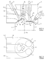
- the reference 1 designates a cylinder head element a cylinder head from a direct injection engine and controlled ignition, arranged above the engine block 3 whose longitudinal axis is perpendicular to the plane of Figure 1.
- This cylinder head element 1 is more particularly arranged above a cylinder cylinder 2 of axis Ax, and inside which slides a piston 4.
- the underside of the cylinder head element 1 has a flat part 13 comprising two inlet ports 7 and 9. This flat part is extended by a dome 14 whose upper face has an orifice receiving a spark plug 16 generally centered by relative to the axis Ax of the engine cylinder (in practice, the spark plug axis 16 and the axis Ax of the engine cylinder can be separated by a few millimeters).
- the dome 14 is extended by an inclined plane 15 comprising a exhaust port 5 cooperating with an exhaust valve 11.
- This exhaust valve 11 controls the opening and closing of an exhaust duct 6 which opens onto one side lateral FL1 of the cylinder head element.
- the exhaust duct 6 extends between the two intake ducts 8 and 10, at a level of height (relative to the underside of the cylinder head element), different from the height level at which the two pipes extend of admission.
- the intake ducts can be arranged so as to generate in the combustion chamber, delimited in particular by the upper side of the piston and by the lower side of the element breech, aerodynamic movements of the "tumble" type.
- a deflector 20, with variable position can be installed in the intake ducts to increase the level of movement "tumble" type vortices.
- the intake ducts can also be arranged for generate a "swirl" type movement in the combustion chamber.
- One can for example close one of the intake ducts.
- an inclined injector 17 is installed on the side of the intake ports 7 and 9.
- the upper face of the piston has a shaped cavity 19 bowl, arranged to exploit mainly the "swirl” component or the “tumble” component of the admitted air mass.
- This cavity 19 is located under the intake valves and also extends up to under the candle 16.
- This cavity 19 is extended by an inclined plane 18 complementary to the inclined plane 15 of the underside of the element cylinder head. This allows in particular to obtain a compression ratio of 10 to 12 in the combustion chamber.
- the injector 17 can be optionally fired called “offset" by relative to the axis of the injector body, so as to optimize the area impact of the jet of fuel (here petrol) on the upper surface piston.
- offset the area impact of the jet of fuel (here petrol) on the upper surface piston.
Landscapes
- Engineering & Computer Science (AREA)
- Chemical & Material Sciences (AREA)
- Combustion & Propulsion (AREA)
- Mechanical Engineering (AREA)
- General Engineering & Computer Science (AREA)
- Combustion Methods Of Internal-Combustion Engines (AREA)
Applications Claiming Priority (2)
| Application Number | Priority Date | Filing Date | Title |
|---|---|---|---|
| FR9710740 | 1997-08-28 | ||
| FR9710740A FR2767867B1 (fr) | 1997-08-28 | 1997-08-28 | Moteur a injection directe et allumage commande |
Publications (1)
| Publication Number | Publication Date |
|---|---|
| EP0899433A1 true EP0899433A1 (de) | 1999-03-03 |
Family
ID=9510555
Family Applications (1)
| Application Number | Title | Priority Date | Filing Date |
|---|---|---|---|
| EP98402004A Withdrawn EP0899433A1 (de) | 1997-08-28 | 1998-08-06 | Fremdgezündete Brennkraftmaschine mit Direkteinspritzung |
Country Status (2)
| Country | Link |
|---|---|
| EP (1) | EP0899433A1 (de) |
| FR (1) | FR2767867B1 (de) |
Citations (5)
| Publication number | Priority date | Publication date | Assignee | Title |
|---|---|---|---|---|
| GB466677A (en) * | 1936-02-21 | 1937-06-02 | Albert George Elliott | Improvements in or relating to the combustion chambers of internal combustion engines and the arrangement of valves therein |
| US4369627A (en) * | 1978-11-07 | 1983-01-25 | Cummins Engine Company, Inc. | Internal combustion engine |
| EP0412009A1 (de) * | 1989-08-02 | 1991-02-06 | Regie Nationale Des Usines Renault | Mehrzylinder-Benzineinspritzmotor mit drei Ventilen pro Zylinder |
| EP0558072A1 (de) * | 1992-02-28 | 1993-09-01 | Mitsubishi Jidosha Kogyo Kabushiki Kaisha | Brennkraftmaschine |
| DE4433280A1 (de) * | 1994-09-19 | 1996-03-28 | Motoren Werke Mannheim Ag | Zylinderkopf |
-
1997
- 1997-08-28 FR FR9710740A patent/FR2767867B1/fr not_active Expired - Fee Related
-
1998
- 1998-08-06 EP EP98402004A patent/EP0899433A1/de not_active Withdrawn
Patent Citations (5)
| Publication number | Priority date | Publication date | Assignee | Title |
|---|---|---|---|---|
| GB466677A (en) * | 1936-02-21 | 1937-06-02 | Albert George Elliott | Improvements in or relating to the combustion chambers of internal combustion engines and the arrangement of valves therein |
| US4369627A (en) * | 1978-11-07 | 1983-01-25 | Cummins Engine Company, Inc. | Internal combustion engine |
| EP0412009A1 (de) * | 1989-08-02 | 1991-02-06 | Regie Nationale Des Usines Renault | Mehrzylinder-Benzineinspritzmotor mit drei Ventilen pro Zylinder |
| EP0558072A1 (de) * | 1992-02-28 | 1993-09-01 | Mitsubishi Jidosha Kogyo Kabushiki Kaisha | Brennkraftmaschine |
| DE4433280A1 (de) * | 1994-09-19 | 1996-03-28 | Motoren Werke Mannheim Ag | Zylinderkopf |
Also Published As
| Publication number | Publication date |
|---|---|
| FR2767867A1 (fr) | 1999-03-05 |
| FR2767867B1 (fr) | 1999-10-22 |
Similar Documents
| Publication | Publication Date | Title |
|---|---|---|
| EP0875670B1 (de) | Brennkraftmaschine mit Direkteinspritzung | |
| US4840147A (en) | Combustion chamber of a two-stroke engine | |
| EP1217186A3 (de) | Direkteinspritzbrennkraftmaschine mit kleinem Sprühwinkel und Verfahren zu ihrer Verwendung | |
| FR2739895A1 (fr) | Moteur a combustion interne a quatre temps et a allumage commande et injection directe de carburant | |
| US5890466A (en) | Device for injecting fuel at the exhaust port of an engine cylinder | |
| JP3333298B2 (ja) | 筒内燃料噴射式の多気筒エンジン | |
| AU2003211595B2 (en) | In-cylinder fuel injection-type internal combustion engine | |
| FR2782345A1 (fr) | Piston a tete a guidage actif, et chambre de combustion associee | |
| EP0889225A1 (de) | Direkteinspritzende Otto-Brennkraftmaschine | |
| EP0879941B1 (de) | Brennkraftmaschine mit Direkteinspritzung und mit Fremdzündung | |
| EP0751286B1 (de) | Brennkraftmaschine mit einer Kraftstoffzufuhreinrichtung | |
| EP0899433A1 (de) | Fremdgezündete Brennkraftmaschine mit Direkteinspritzung | |
| EP0296899B1 (de) | Anlage eines Brennstoffzufuhrsystems in einer Zweitaktmotorbrennkammer hinsichtlich der Auslassöffnung | |
| EP0945604A1 (de) | Fremdgezündete Viertaktbrennkraftmaschine mit Direkteinspritzung | |
| EP0209426B1 (de) | Zylinderkopf einer Brennkraftmaschine mit drei Ventilen pro Zylinder | |
| EP0881370B1 (de) | Neue Anordnung für eine fremdgezündete, direkteinspritzende Viertaktbrennkraftmaschine | |
| FR2926849A1 (fr) | Moteur thermique de vehicule automobile a chambres de combustion de rendement eleve. | |
| FR2716495A1 (fr) | Dispositions permettant d'améliorer le fonctionnement des moteurs Diesel à injection directe. | |
| FR2771138A1 (fr) | Moteur a injection directe et allumage commande | |
| FR2712028A1 (fr) | Moteur à combustion interne à injection indirecte de carburant. | |
| EP0983426B1 (de) | Brennkraftmaschine mit fremdzündung | |
| FR2763996A1 (fr) | Moteur a combustion interne a allumage commande comportant trois soupapes par cylindre | |
| EP0881368A1 (de) | Direkteinspritzbrennkraftmaschine mit Fremdzündung | |
| FR2720784A1 (fr) | Moteur à combustion interne à plusieurs soupapes d'admission par cylindre. | |
| EP0878613A1 (de) | Direkteinspritzbrennkraftmaschine mit Zündvorrichtung |
Legal Events
| Date | Code | Title | Description |
|---|---|---|---|
| PUAI | Public reference made under article 153(3) epc to a published international application that has entered the european phase |
Free format text: ORIGINAL CODE: 0009012 |
|
| AK | Designated contracting states |
Kind code of ref document: A1 Designated state(s): DE ES GB IT |
|
| AX | Request for extension of the european patent |
Free format text: AL;LT;LV;MK;RO;SI |
|
| 17P | Request for examination filed |
Effective date: 19990901 |
|
| AKX | Designation fees paid |
Free format text: DE ES GB IT |
|
| GRAG | Despatch of communication of intention to grant |
Free format text: ORIGINAL CODE: EPIDOS AGRA |
|
| 17Q | First examination report despatched |
Effective date: 20020207 |
|
| STAA | Information on the status of an ep patent application or granted ep patent |
Free format text: STATUS: THE APPLICATION HAS BEEN WITHDRAWN |
|
| 18W | Application withdrawn |
Withdrawal date: 20020610 |