EP0899232B1 - Fork lift truck with structure to join lifting cylinder - Google Patents
Fork lift truck with structure to join lifting cylinder Download PDFInfo
- Publication number
- EP0899232B1 EP0899232B1 EP98116268A EP98116268A EP0899232B1 EP 0899232 B1 EP0899232 B1 EP 0899232B1 EP 98116268 A EP98116268 A EP 98116268A EP 98116268 A EP98116268 A EP 98116268A EP 0899232 B1 EP0899232 B1 EP 0899232B1
- Authority
- EP
- European Patent Office
- Prior art keywords
- cargo
- handling
- masts
- connecting member
- hand
- Prior art date
- Legal status (The legal status is an assumption and is not a legal conclusion. Google has not performed a legal analysis and makes no representation as to the accuracy of the status listed.)
- Expired - Lifetime
Links
- 238000003780 insertion Methods 0.000 claims description 29
- 230000037431 insertion Effects 0.000 claims description 29
- 238000000926 separation method Methods 0.000 claims description 4
- 230000007246 mechanism Effects 0.000 description 13
- 230000004048 modification Effects 0.000 description 11
- 238000012986 modification Methods 0.000 description 11
- 230000001419 dependent effect Effects 0.000 description 1
Images


Classifications
-
- B—PERFORMING OPERATIONS; TRANSPORTING
- B66—HOISTING; LIFTING; HAULING
- B66F—HOISTING, LIFTING, HAULING OR PUSHING, NOT OTHERWISE PROVIDED FOR, e.g. DEVICES WHICH APPLY A LIFTING OR PUSHING FORCE DIRECTLY TO THE SURFACE OF A LOAD
- B66F9/00—Devices for lifting or lowering bulky or heavy goods for loading or unloading purposes
- B66F9/06—Devices for lifting or lowering bulky or heavy goods for loading or unloading purposes movable, with their loads, on wheels or the like, e.g. fork-lift trucks
- B66F9/075—Constructional features or details
- B66F9/08—Masts; Guides; Chains
Definitions
- the present invention relates to a fork lift truck with a structure to join a cylinder lifting a cargo-handling tool according to the preamble portion of claims 1, 7, 10, 11, 13 and 14.
- a fork lift truck with such a structure is disclosed in figure 5 of the present application.
- Cargo-lifting mechanisms of a type having a structure as schematically shown in Fig. 1 are known, the cargo-lifting mechanism having three pairs of masts provided with a free lift.
- the foregoing lifting mechanism incorporates a pair of right-hand and left-hand (in a direction perpendicular to the surface of a drawing sheet) outer masts 1 secured to a front portion of the forklift truck.
- a pair of right-hand and left-hand middle masts 3 are provided for the outer masts 1 such that vertical movement of the middle masts 3 is permitted.
- a pair of right-hand and left-hand inner masts 5 which are capable of moving vertically are provided for the middle masts 3.
- the inner masts 5 are provided with a fork serving as a cargo-handling tool on which a cargo is placed such that vertical movement of the fork 7 is permitted.
- a cargo-handling-tool lifting cylinder (a full-free cylinder) 9 for vertically moving the fork 7 is secured to a position adjacent to the inner masts 5.
- the fork 7 and the inner masts 5 are connected to each other by dint of a chain 15 through a chain sprocket 13 disposed at the top end of a cylinder rod 11 of the cargo-handling-tool lifting cylinder 9.
- the cargo-handling-tool lifting cylinder 9 When the cargo-handling-tool lifting cylinder 9 is operated, the fork 7 is vertically moved with respect to the inner masts 5.
- mast-lifting cylinders 17 for vertically moving the middle masts 3 and the inner masts 5 are disposed at positions adjacent to the outer masts 1.
- the outer masts 1 and the inner masts 5 are connected to each other by dint of a chain 21 through chain sprockets 19 disposed on the upper portions of the middle masts 3.
- the inner masts 5 are moved vertically with respect to the outer masts 1 for a distance which is twice the distance for which the middle masts 3 is vertically moved.
- Fig. 2 is a plan view showing a specific structure of the above-mentioned lifting mechanism.
- the lower ends of the pairs of the right-hand and the left-hand outer masts 1, middle masts 3 and the inner masts 5 are connected to each other by an outer-mast lower beam 23, a middle-mast lower beam 25 and an inner-mast lower beam 27.
- the pair of right-hand and left-hand mast-lifting cylinders 17 for vertically moving the middle masts 3 are elongated vertically on the outer-mast lower beam 23 disposed in the rear of the outer masts 1.
- the cargo-handling-tool lifting cylinder 9 for upwardly moving the fork 7 is elongated vertically on a cylinder support 29 which is disposed between the right-hand and left-hand inner masts 5 and which forwards projects over the inner-mast lower beam 27.
- the fork 7 is joined to the front surface of a carriage 33 secured to the leading ends of a pair of carriage brackets 31 disposed on the inside of the inner masts 5.
- Mast rollers 35 are joined to the side surfaces of the upper and lower ends of the carriage brackets 31. When the mast rollers 35 vertically roll with respect to the inner masts 5, the carriage brackets 31, the carriage 33 and the fork 7 are vertically moved with respect to the inner masts 5.
- Mast rollers (not shown in Fig. 2) are disposed between the outer masts 1 and the middle masts 3 and between the middle masts 3 and the inner masts 5 (for example, mast rollers 36 are disposed in the lower portions of the inner masts 5 as shown in Fig. 3 to be described later).
- Lift-mechanism support brackets 37 for mounting the foregoing lifting mechanism on the forklift truck are disposed at the right and left ends of the outer-mast lower beam 23.
- the distance from the joining center of each of the lift-mechanism support brackets 37 to the carriage 33 is a front overhang (FOH).
- FOH front overhang
- Fig. 3 is a perspective view showing the inner masts 5 and the cargo-handling-tool lifting cylinder 9 which is joined to the inner masts 5.
- a threaded hole 29a is formed in the upper surface of the cylinder support 29 provided for the inner-mast lower beam 27.
- a bolt 39 is screwed in the threaded hole 29a.
- a locating recess 9a into which the head of the bolt 39 is introduced is formed in the lower surface of the cargo-handling-tool lifting cylinder 9.
- brackets 41 disposed at positions relatively upper than the central portion of the cargo-handling-tool lifting cylinder 9 are secured to a center beam 43 with two bolts 45, the center beam 43 establishing the connection between intermediate portions of the inner masts 5 in the vertical direction.
- the cargo-handling-tool lifting cylinder 9 is joined to a position adjacent to the inner masts 5.
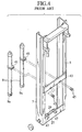
- Fig. 4 shows an example in which two cargo-handling-tool lifting cylinders 9 are employed.
- the cylinders 9 are disposed at positions adjacent to the right and left inner masts 5.
- pins 47 disposed on a cylinder support 29 are received by recesses 9a formed in the lower surface of the cargo-handling-tool lifting cylinder 9.
- brackets 41 provided for the cargo-handling-tool lifting cylinder 9 are secured to the center beam 43 with bolts 45.
- the example of the structure for joining a cylinder for lifting a cargo-handling tool of the type shown in Fig. 3 has the arrangement that the cargo-handling-tool lifting cylinder 9 is disposed at an intermediate position between the right and left inner masts 5. Therefore, forward visibility is unsatisfactory for an operator of the forklift truck to efficiently Perform the cargo handling operation.
- the example shown in Fig. 4 incorporates the two cargo-handling-tool lifting cylinders 9 disposed at the right and left positions. Therefore, the forward visibility can be improved as compared with the example shown in Fig. 3.
- the cargo-handling-tool lifting cylinders 9 are disposed between the carriage brackets 31 shown in Fig. 2. Therefore, the visibility for the forklift operator is obstructed. Thus, further improvement in the visibility is required.
- a fork lift truck with a structure to join a cylinder lifting a cargo-handling tool according to the preamble of claims 1, 7, 10, 11, 13 and 14 will now be described with reference to figure 5.
- a structure may be employed in which brackets 41 for securing the cargo-handling-tool lifting cylinders 9 are, as shown in Fig. 5 which is a plan view, secured to the center beam 43 by dint of bolts 45 from front positions of the forklift truck.
- heads of the bolts 45 interfere with the inner masts 5. Therefore, satisfactorily improved forward visibility cannot be obtained.
- the cargo-handling-tool lifting cylinders 9 To reduce the front overhang (FOH), the cargo-handling-tool lifting cylinders 9 must be disposed at positions closer to the center beam 43. If the distance is too short, the leading end of the bolts 45 screwed in the brackets 41 interfere with the cargo-handling-tool lifting cylinders 9. To prevent the interference, the distance between the two bolts 45 must be elongated. Moreover, the cargo-handling-tool lifting cylinders 9 must be disposed closer to the central portion. If the distance between the bolts 45 is elongated, the size of each of the brackets 41 is enlarged excessively to easily handle the brackets 41. What is worse, the forward visibility deteriorates. As a matter of course, the forward visibility deteriorates if the cargo-handling-tool lifting cylinders 9 is disposed adjacent to the central portion.
- Fig. 6 is a plan view showing the overall structure of a lifting mechanism of a forklift truck.
- Fig. 7 is a plan view showing an essential portion of the lifting mechanism.
- a center beam 51 serving as a plate-like connecting member for connecting a pair of right-hand and left-hand inner masts 49 is disposed at substantially the vertical center (in a direction perpendicular to a drawing sheet on which Fig. 6 is drawn) of inner masts 49 which are second masts.
- Cargo-handling-tool lifting cylinders 53 are, through the brackets 55, secured to the center beam 51 at positions in the rear of the right and left inner masts 49.
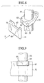
- the brackets 55 has insertion holes 57 into which the cargo-handling-tool lifting cylinders 53 are inserted and supported. Moreover, engaging projections 61 projecting forwards are provided for end surfaces 59 which are in close contact with a rear surface of the center beam 51. Each of the engaging projections 61 has a width somewhat smaller than the outer diameter of each of the cargo-handling-tool lifting cylinders 53. The engaging projections 61 are formed in front of the cargo-handling-tool lifting cylinders 53. As shown in Fig. 8 which is an exploded perspective view of a joint portion shown in Fig.
- the width of a front portion of each of the engaging projections 61 is larger than the width of a rear portion of each of the engaging projections 61.
- inclined surfaces 63 and 65 are formed on the two sides of each of the engaging projections 61.
- FIG. 9 is a view IX showing a state of Fig.8 in which the engaging projection 61 is joined to the engaging recess 67.
- a front portion of the engaging recess 67 has a width larger than the width of a rear portion of the engaging recess 67 in order to enable the engaging recess 67 to be joined to the engaging projection 61.
- inclined surfaces 69 and 71 corresponding to the inclined surfaces 63 and 65 are formed. As shown in Fig.
- a front surface 83 of the engaging projections 61 is positioned slightly inner than the front surface of the center beam 51 in a state in which the engaging projection 61 is joined to the engaging recess 67.
- the front surface 83 is substantially flush with the front surface of the center beam 51.
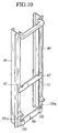
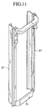
- Figs. 10, 11 and 12 are perspective views of the inner masts 49, middle masts 87 and outer masts 85.
- the middle masts 87 and outer masts 85 constitute first masts which are cooperating with the aforementioned second masts. From time to time, only the outer masts 85 constitute the first masts depending upon variety of designing of the forklift truck.
- a pair of the right-hand and left-hand inner masts 49, middle masts 87 and the outer masts 85 have lower ends which are connected to each other by dint of a corresponding inner-mast lower beam 89, a middle-mast lower beam 91 and an outer-mast lower beam 93.
- a pair of right-hand and left-hand mast-lifting cylinders 95 for vertically moving the middle masts 87 are extended on the outer-mast lower beam 93 in the rear of the outer masts 85.
- a pair of right-hand and left-hand cargo-handling-tool lifting cylinders 53 for upwardly moving a fork 99, which is joined to the front surface of a carriage 97 and which serves as a cargo-handling tool, are disposed in the rear of the pair of right-hand and left-hand inner masts 49, the cargo-handling-tool lifting cylinders 53 being extended vertically.
- the carriage 97 is secured to a leading end of each of carriage brackets 101.
- Rollers 103 arranged to be moved vertically while the rollers 103 are rotated with respect to the inner masts 49 are joined to the side surfaces of the carriage brackets 101 adjacent to the top and lower ends of the inner masts 49.
- cylinder supports 105 for supporting the lower ends of the cargo-handling-tool lifting cylinders 53 are joined to the rear portions of the inner-mast lower beam 89 adjacent to the inner masts 49. Projections 105a formed at the top ends of the cylinder supports 105 upwards project over the inner-mast lower beam 89.
- grooves (not shown) each extending in the widthwise direction of the forklift truck are formed at the lower ends of the cargo-handling-tool lifting cylinders 53. Projections 105a of the cylinder supports 105 are introduced into the grooves.
- the operation for mounting the cargo-handling-tool lifting cylinders 53 on the inner masts 49 is performed by joining the engaging projections 61 provided for the center beam 51 for supporting the cargo-handling-tool lifting cylinders 53 to the engaging recesses 67 provided for the center beam 51 as described above. Therefore, the operation can easily be performed. Thus, the workability in the assembling operation can be improved.
- the cargo-handling-tool lifting cylinders 53 are disposed in the rear of the inner masts 49. Specifically, the cargo-handling-tool lifting cylinders 53 are disposed in the rear of the carriage brackets 101. Since the cargo-handling-tool lifting cylinders 53 are not disposed between the carriage brackets 101, satisfactory forward visibility is permitted between the carriage brackets 101.
- the joint portion consisting of the engaging projections 61 and the engaging recesses 67 is formed in front of the cargo-handling-tool lifting cylinders 53.
- the front surfaces 83 of the engaging projections 61 is formed at positions somewhat inner position as compared with the front surface of the center beam 51 and the substantially flush surface is formed.
- brackets 55 can be joined to the center beam 51 at further outer positions in the widthwise direction of the forklift truck (at a left-hand position in Fig. 7). Since the cargo-handling-tool lifting cylinders 53 can be disposed at outer positions in the widthwise direction of the forklift truck, the forward visibility can furthermore be improved.
- this embodiment is not required to secure the brackets 55 with bolts from forward positions of the forklift truck in order to prevent interference with the cargo-handling-tool lifting cylinders 53, the cargo-handling-tool lifting cylinders 53 can be disposed more forwards so as to dispose the cargo-handling-tool lifting cylinders 53 adjacent to the center beam 51. Therefore, the front overhang can be reduced. Since fixing bolts are not required, any bolt fixing portion is not required for the brackets 55. Thus, the widthwise length can be reduced and therefore the forward visibility can be improved.
- Fig. 13 shows a modification of the first embodiment.
- the bracket 55 is secured to the center beam 51 with a bolt 81.
- a flange 75 projecting to the central portion of the forklift truck is formed on the side surface of the brackets 55 adjacent to the central portion of the forklift truck, that is, on a right-hand side surface shown in Fig. 13.
- the flange 75 has a bolt insertion hole 77, while a threaded hole 79 corresponding to the bolt insertion hole 77 is formed at a position adjacent to the center beam 51.
- the distance between the inclined surfaces 63 and 65 of each of the engaging projections 61 is shorter than the distance between the inclined surfaces 69 and 71 of the engaging recess 67. As a result, a gap 73 is formed between the engaging projection 61 and the engaging recess 67.
- the inclined surfaces 63 and 69 in the outer portion of the forklift truck are in close contact with each other.
- the inclined surface 63 of the engaging projections 61 formed at an outer position in the widthwise direction of the forklift truck is located in a state in which the inclined surface 63 is in close contact with the inclined surface 69 of the engaging recess 67.
- the bolts 81 are screwed in so that the brackets 55 are secured to the center beam 51.
- a play is permitted between the engaging projection 61 and the engaging recess 67 by dint of the gap 73. Therefore, the joining operation can easily be performed.
- the brackets 55 can reliably be secured to the center beam 51 by the bolts 81.
- Fig. 14 is an exploded perspective view showing an essential portion of a modification of the first embodiment of the present invention, that is, a joint portion in which the brackets 55 for supporting the cargo-handling-tool lifting cylinders 53 and the center beam 51 are joined to each other.
- the joint portion according to this embodiment has a structure that a joining projection 107 is formed on the end surfaces 59 of each of the brackets 55.
- a joining recess 109 is formed in the upper surface of the center beam 51.
- the joining projection 107 has a neck portion 107a which is introduced into the joining recess 109 and an engaging projection 107b formed in front of the neck portion 107a and projecting horizontally at a position in front of the center beam 51.
- the neck portion 107a When the neck portion 107a is joined to the joining recess 109, the end surface 59 is brought into contact with the center beam 51. Since the engaging projection 107b is positioned at a position opposite to the contact portion, the brackets 55 can be joined to the center beam 51.
- the width of the engaging projection 107b is substantially the same as the outer diameter of the cargo-handling-tool lifting cylinder 53.
- the joint portions are formed in front of the cargo-handling-tool lifting cylinders 53. Therefore, the brackets 55 despite projecting forwards can be disposed at outer positions in the widthwise direction of the forklift truck. Thus, satisfactory forward visibility can be realized. Since the cargo-handling-tool lifting cylinders 53 can be disposed adjacently at positions adjacent to the center beam 51, the front overhang can be reduced.
- Fig. 15 shows a modification of the embodiment shown in Fig. 14.
- the joining recess 109 of the center beam 51 is provided with a neck-portion receiving portion 109a into which the neck portion 107a is introduced and an engaging-projection receiving portion 109b into which the engaging projection 107b is introduced.
- the engaging projection 107b is introduced into the engaging-projection receiving portion 109b of the center beam 51 so that the engaging projection 107b does not forwards project over the center beam 51. Therefore, the brackets 55 can be disposed at further outer positions as compared with the structure shown in Fig. 13.
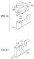
- Fig. 16 shows a second embodiment of the present invention.
- a joining groove 111 extending in the widthwise direction of the forklift truck is formed in the lower surface of a projection portion 55a provided for the front end surfaces 59 of the bracket 55.
- a recess 113 corresponding to the joining groove 111 is formed in the upper end portion of the center beam 51.
- a joining portion is constituted.
- the widthwise size of the projection portion 55a of the bracket 55 provided with the joining groove 111 is substantially the same as the outer diameter of the cargo-handling-tool lifting cylinder 53.
- a joining portion is formed in front of the cargo-handling-tool lifting cylinder 53.
- the brackets 55 can be disposed at further outer positions with respect to the center beam 51.
- the embodiment shown in Fig. 16 may be arranged such that the recess 113 of the center beam 51 is omitted.
- Fig. 17 shows a modification of the embodiment shown in Fig. 16.
- the recess 113 has a joining-groove receiving portion 113a into which the joining groove 111 is introduced and a notch 113b formed in front of the joining-groove receiving portion 113a. Since the engaging portion 115 of the bracket 55 is introduced into the notch 113b, forward projection of the projection portion 55a of the brackets 55 over the center beam 51 can be prevented. As a result, the cargo-handling-tool lifting cylinders 53 can be disposed further outer positions in the widthwise direction of the forklift truck as compared with the structure shown in Fig. 16.
- Fig. 18 shows a third embodiment of the present invention.
- a pair of joining pins 117 are disposed at the top end of the center beam 51.
- a joining hole 119 into which the joining pin 117 is inserted is formed in the upper surface of the bracket 55.
- a front end 55b of the brackets 55 provided with the joining hole 119 has a widthwise size which is substantially the same as the outer diameter of the cargo-handling-tool lifting cylinder 53.
- the joint portion is formed at a position in front of the cargo-handling-tool lifting cylinder 53.
- the brackets 55 can be disposed at further outer positions in the widthwise direction of the forklift truck with respect to the center beam 51.
- the embodiment shown in Fig. 18 may be arranged such that a bolt employed in place of the pin 117 is screwed in the top end of the center beam 51. Moreover, a receiving hole for receiving the head of the bolt allowed to appear may be formed.
- the joining pin 117 may be provided for the brackets 55, while the joining hole 119 may be provided for the center beam 51.
- Figs. 19 and 20 show a fourth embodiment of the present H fourth invention.
- a rectangular through hole 121 is provided for the center beam 51.
- an insertion projection 123 arranged to be inserted into the through hole 121 is provided for the brackets 55.
- the insertion projection 123 has a projection 123a projecting forwards over the center beam 51 as shown in Fig. 19.
- a bolt 124 serving as the engaging member is, from an upper position, screwed in a threaded hole 123b formed in the projection 123a and serving as the engaging hole. Since the head of the bolt 124 appears outside, separation of the insertion projection 123 from the through hole 121 can be prevented.
- the brackets 55 can be secured to the center beam 51.
- the end surfaces 59 of the brackets 55 are brought into contact with the center beam 51.
- the width of the insertion projection 123 is substantially the same as the outer diameter of the cargo-handling-tool lifting cylinder 53.
- the joining portion is formed in front of the cargo-handling-tool lifting cylinders 53.
- the brackets 55 can be disposed at further outer positions with respect to the center beam 51.
- a pin having a heed may be employed in place of the bolt 124, the pin being inserted into a pin insertion hole formed in place of the threaded hole 123b.
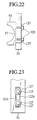
- Figs. 21 to 23 show a fifth embodiment of the present invention.
- This embodiment has a structure similar to that shown in Fig. 19 in which a through hole 121 is provided for the center beam 51; and an insertion projection 123 which is inserted into the through hole 121 is provided for the bracket 55.
- the insertion projection 123 according to this embodiment has a front surface 123c which does not forwards project over the front surface of the center beam 51.
- the front surface 123c is substantially flush with the foregoing front surface of the center beam 51.
- Fig. 22 which is a plan view showing an assembled state
- Fig. 23 which is a right-hand side view of Fig. 22
- bolts 125 are screwed in two threaded holes 123d formed in the front surface of the 123c through washers 127 as intermediators for preventing separation.
- the bolts 125 are screwed in at front positions of the forklift truck.
- the brackets 55 can be disposed at further outer positions in the widthwise direction of the forklift truck with respect to the center beam 51. Even if the pitch between the bolts 125 is shortened and thus the bolts are disposed in front of the cargo-handling-tool lifting cylinders 53, the leading end of the threaded portion of each of the bolt 125 can be accommodated in the insertion projection 123 of the bracket 55. Therefore, interference with the cargo-handling-tool lifting cylinders 53 can be prevented. Thus, the cargo-handling-tool lifting cylinders 53 can be disposed further adjacently to the center beam 51. Thus, the front overhang can be reduced without any problem.
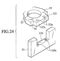
- Figs. 24 to 26 show a sixth embodiment of the present invention.
- the bracket 55 is provided with an insertion projection 123 similar to that according to the embodiment shown in Fig. 21.
- a recess 129 into which the insertion projection 123 is inserted from an upper position is provided for the center beam 51.
- the insertion projection 123 has two bolt insertion holes 123e to vertically penetrate the insertion projection 123.
- the recess 129 has threaded holes 129a corresponding to the bolt insertion holes 123e.
- Fig. 25 which is a plan view showing an assembled state
- Fig. 26 which is a right-hand side view
- the brackets 55 can be secured to the center beam 51.
- the end surfaces 59 of the brackets 55 are brought into contact with the center beam 51.
- the front surface 123c of the insertion projection 123 is substantially flush with the front surface of the center beam 51.
- the second and following embodiments may be structured such that bolts may be employed which are screwed in from the outer portions of the brackets 55.
- Fig. 27 shows an example which does not form part of the claimed invention in which a fixing member 133 having an engaging recess 133a to which the engaging projection 61 of the bracket 55 for supporting the cargo-handling-tool lifting cylinders 53 shown in Fig. 6 is joined is joined to a position upper than the center beam 51 for connecting the right and left inner masts 49.
- the present invention may be applied to a lifting mechanism having two pairs of masts, that is, having no middle mast.
- the outer masts are first masts.
Landscapes
- Engineering & Computer Science (AREA)
- Transportation (AREA)
- Structural Engineering (AREA)
- Civil Engineering (AREA)
- Life Sciences & Earth Sciences (AREA)
- Geology (AREA)
- Mechanical Engineering (AREA)
- Forklifts And Lifting Vehicles (AREA)
Description
- The present invention relates to a fork lift truck with a structure to join a cylinder lifting a cargo-handling tool according to the preamble portion of
claims - A fork lift truck with such a structure is disclosed in figure 5 of the present application.
- Cargo-lifting mechanisms of a type having a structure as schematically shown in Fig. 1 are known, the cargo-lifting mechanism having three pairs of masts provided with a free lift. The foregoing lifting mechanism incorporates a pair of right-hand and left-hand (in a direction perpendicular to the surface of a drawing sheet)
outer masts 1 secured to a front portion of the forklift truck. A pair of right-hand and left-hand middle masts 3 are provided for theouter masts 1 such that vertical movement of themiddle masts 3 is permitted. Moreover, a pair of right-hand and left-handinner masts 5 which are capable of moving vertically are provided for themiddle masts 3. Theinner masts 5 are provided with a fork serving as a cargo-handling tool on which a cargo is placed such that vertical movement of thefork 7 is permitted. - A cargo-handling-tool lifting cylinder (a full-free cylinder) 9 for vertically moving the
fork 7 is secured to a position adjacent to theinner masts 5. Thefork 7 and theinner masts 5 are connected to each other by dint of achain 15 through achain sprocket 13 disposed at the top end of acylinder rod 11 of the cargo-handling-tool lifting cylinder 9. When the cargo-handling-tool lifting cylinder 9 is operated, thefork 7 is vertically moved with respect to theinner masts 5. - On the other hand, mast-
lifting cylinders 17 for vertically moving themiddle masts 3 and theinner masts 5 are disposed at positions adjacent to theouter masts 1. Theouter masts 1 and theinner masts 5 are connected to each other by dint of achain 21 throughchain sprockets 19 disposed on the upper portions of themiddle masts 3. When themiddle masts 3 are moved vertically because of the operation of the mast-lifting cylinders 17, theinner masts 5 are moved vertically with respect to theouter masts 1 for a distance which is twice the distance for which themiddle masts 3 is vertically moved. - Fig. 2 is a plan view showing a specific structure of the above-mentioned lifting mechanism. The lower ends of the pairs of the right-hand and the left-hand
outer masts 1,middle masts 3 and theinner masts 5 are connected to each other by an outer-mastlower beam 23, a middle-mastlower beam 25 and an inner-mastlower beam 27. The pair of right-hand and left-hand mast-lifting cylinders 17 for vertically moving themiddle masts 3 are elongated vertically on the outer-mastlower beam 23 disposed in the rear of theouter masts 1. On the other hand, the cargo-handling-tool liftingcylinder 9 for upwardly moving thefork 7 is elongated vertically on acylinder support 29 which is disposed between the right-hand and left-handinner masts 5 and which forwards projects over the inner-mastlower beam 27. - The
fork 7 is joined to the front surface of acarriage 33 secured to the leading ends of a pair ofcarriage brackets 31 disposed on the inside of theinner masts 5.Mast rollers 35 are joined to the side surfaces of the upper and lower ends of thecarriage brackets 31. When themast rollers 35 vertically roll with respect to theinner masts 5, thecarriage brackets 31, thecarriage 33 and thefork 7 are vertically moved with respect to theinner masts 5. Mast rollers (not shown in Fig. 2) are disposed between theouter masts 1 and themiddle masts 3 and between themiddle masts 3 and the inner masts 5 (for example,mast rollers 36 are disposed in the lower portions of theinner masts 5 as shown in Fig. 3 to be described later). - Lift-
mechanism support brackets 37 for mounting the foregoing lifting mechanism on the forklift truck (a front axle shaft) are disposed at the right and left ends of the outer-mastlower beam 23. The distance from the joining center of each of the lift-mechanism support brackets 37 to thecarriage 33 is a front overhang (FOH). When the FOH is reduced, the distance from the forklift truck to a portion for holding a cargo can be shortened. Thus, a cargo-handling operation can stably be performed. - Fig. 3 is a perspective view showing the
inner masts 5 and the cargo-handling-tool lifting cylinder 9 which is joined to theinner masts 5. A threadedhole 29a is formed in the upper surface of thecylinder support 29 provided for the inner-mastlower beam 27. Abolt 39 is screwed in the threadedhole 29a. On the other hand, a locatingrecess 9a into which the head of thebolt 39 is introduced is formed in the lower surface of the cargo-handling-tool lifting cylinder 9. - In a state in which the locating
recess 9a of the cargo-handling-tool lifting cylinder 9 is received by the head of thebolt 39 jointed to the upper surface of thecylinder support 29,brackets 41 disposed at positions relatively upper than the central portion of the cargo-handling-tool lifting cylinder 9 are secured to acenter beam 43 with twobolts 45, thecenter beam 43 establishing the connection between intermediate portions of theinner masts 5 in the vertical direction. Thus, the cargo-handling-tool lifting cylinder 9 is joined to a position adjacent to theinner masts 5. - Fig. 4 shows an example in which two cargo-handling-
tool lifting cylinders 9 are employed. Thecylinders 9 are disposed at positions adjacent to the right and leftinner masts 5. In the foregoing example,pins 47 disposed on acylinder support 29 are received byrecesses 9a formed in the lower surface of the cargo-handling-tool lifting cylinder 9. In the foregoing state,brackets 41 provided for the cargo-handling-tool lifting cylinder 9 are secured to thecenter beam 43 withbolts 45. - The example of the structure for joining a cylinder for lifting a cargo-handling tool of the type shown in Fig. 3 has the arrangement that the cargo-handling-
tool lifting cylinder 9 is disposed at an intermediate position between the right and leftinner masts 5. Therefore, forward visibility is unsatisfactory for an operator of the forklift truck to efficiently Perform the cargo handling operation. The example shown in Fig. 4 incorporates the two cargo-handling-tool lifting cylinders 9 disposed at the right and left positions. Therefore, the forward visibility can be improved as compared with the example shown in Fig. 3. However, the cargo-handling-tool lifting cylinders 9 are disposed between thecarriage brackets 31 shown in Fig. 2. Therefore, the visibility for the forklift operator is obstructed. Thus, further improvement in the visibility is required. - To improve the forward visibility, a structure is disclosed in Japanese Utility-Model Applications Laid-Open No. 57-155198 and Laid-Open No. 59-123096, the structure is formed such that cargo-handling-
tool lifting cylinders 9 are disposed adjacently toinner masts 5 at positions in the rear of theinner masts 5. - A fork lift truck with a structure to join a cylinder lifting a cargo-handling tool according to the preamble of
claims tool lifting cylinders 9 are disposed adjacently to theinner masts 5 at positions in the rear of theinner masts 5, a structure may be employed in whichbrackets 41 for securing the cargo-handling-tool lifting cylinders 9 are, as shown in Fig. 5 which is a plan view, secured to thecenter beam 43 by dint ofbolts 45 from front positions of the forklift truck. To improve the forward visibility by disposing the cargo-handling-tool lifting cylinders 9 at further outer positions in the widthwise direction of the forklift truck, heads of thebolts 45 interfere with theinner masts 5. Therefore, satisfactorily improved forward visibility cannot be obtained. - To reduce the front overhang (FOH), the cargo-handling-
tool lifting cylinders 9 must be disposed at positions closer to thecenter beam 43. If the distance is too short, the leading end of thebolts 45 screwed in thebrackets 41 interfere with the cargo-handling-tool lifting cylinders 9. To prevent the interference, the distance between the twobolts 45 must be elongated. Moreover, the cargo-handling-tool lifting cylinders 9 must be disposed closer to the central portion. If the distance between thebolts 45 is elongated, the size of each of thebrackets 41 is enlarged excessively to easily handle thebrackets 41. What is worse, the forward visibility deteriorates. As a matter of course, the forward visibility deteriorates if the cargo-handling-tool lifting cylinders 9 is disposed adjacent to the central portion. - The above-mentioned structure in which the cargo-handling-
tool lifting cylinders 9 disposed adjacent to theinner masts 5 and in the rear of theinner masts 5 is secured from the front positions of the forklift truck with thebolts 45 cannot permit a satisfactorily wide forward visibility to be obtained. If the cargo-handling-tool lifting cylinders 9 are disposed closer to thecenter beam 43 in order to satisfy the FOH, the forward visibility furthermore deteriorates. Therefore, an improvement is required. - The present invention has been achieved with such points in mind.
- It is an object underlying the present invention to provide a forklift truck with a structure to join a cylinder lifting a cargo-handling-tool according to the preamble part of
claims - The solution of this object is achieved by the combination of features of
claims - The above and further objects and novel features of the present invention will more fully appear from the following detailed description when the same is read in conjunction with the accompanying drawings, in which:
- Fig. 1 is a schematic view showing a cargo-lifting mechanism having three pairs of masts provided with a free lift of a forklift truck;
- Fig. 2 is a schematic plan view showing a lifting mechanism provided with a conventional structure for joining a cylinder for lifting a cargo-handling tool;
- Fig. 3 is a perspective view showing inner masts and cargo-handling-tool lifting cylinders joined to the inner masts of the lifting mechanism shown in Fig. 2;
- Fig. 4 is a perspective view showing a structure in which two cargo-handling-tool lifting cylinders are employed similarly to a structure shown in Fig. 3;
- Fig. 5 is a plan view showing a structure in which two cargo-handling-tool lifting cylinders are employed similarly to a structure shown in Fig. 2;
- Fig. 6 is a plan view showing the overall structure of a lifting mechanism of a forklift truck according to a first embodiment of the present invention;
- Fig. 7 is an enlarged plan view showing an essential portion of the structure shown in Fig. 6;
- Fig. 8 is an exploded perspective view showing the portion shown in Fig. 7 when it is viewed from a front left portion of the forklift truck;
- Fig. 9 is a view of the arrow IX shown in Fig. 8 as a state in which the elements shown in Fig. 8 have been mounted;
- Fig. 10 is a perspective view showing the inner masts of the forklift truck shown in Fig. 6;
- Fig. 11 is a perspective view showing the middle masts of the forklift truck shown in Fig. 6;
- Fig. 12 is a perspective view showing the outer masts of the forklift truck shown in Fig. 6;
- Fig. 13 is a plan view showing an essential portion of a modification of the first embodiment shown in Fig. 6;
- Fig. 14 is an exploded perspective view showing an essential portion of a modification of the first embodiment of the present invention;
- Fig. 15 is a perspective view showing an essential portion of a center beam according to a modification of the embodiment shown in Fig. 14;
- Fig. 16 is an exploded perspective view showing an essential portion of a second embodiment of the present invention;
- Fig. 17 is a perspective view showing an essential portion of the center beam according to a modification of the embodiment shown in Fig. 16;
- Fig. 18 is an exploded perspective view showing an essential portion of a third embodiment of the present invention;
- Fig. 19 is an exploded perspective view showing an essential portion of a fourth embodiment of the present invention;
- Fig. 20 is a side view showing a state in which the elements shown in Fig. 19 have been mounted;
- Fig. 21 is an exploded perspective view showing a fifth embodiment of the present invention;
- Fig. 22 is a plan view showing a state in which the elements shown in Fig. 21 have been mounted;
- Fig. 23 is a right-hand side view of Fig. 22;
- Fig. 24 is an exploded perspective view showing an essential portion of a sixth embodiment of the present invention: H sixth
- Fig. 25 is a plan view showing a state in which the elements shown in Fig. 24 have been mounted;
- Fig. 26 is a right-hand side view of Fig. 25.
- There will be detailed below the preferred embodiments of the present invention with reference to the accompanying drawings. Like members are designated by like reference characters.
- Fig. 6 is a plan view showing the overall structure of a lifting mechanism of a forklift truck. Fig. 7 is a plan view showing an essential portion of the lifting mechanism. A
center beam 51 serving as a plate-like connecting member for connecting a pair of right-hand and left-handinner masts 49 is disposed at substantially the vertical center (in a direction perpendicular to a drawing sheet on which Fig. 6 is drawn) ofinner masts 49 which are second masts. Cargo-handling-tool lifting cylinders 53 are, through thebrackets 55, secured to thecenter beam 51 at positions in the rear of the right and leftinner masts 49. - The
brackets 55 has insertion holes 57 into which the cargo-handling-tool lifting cylinders 53 are inserted and supported. Moreover, engagingprojections 61 projecting forwards are provided for end surfaces 59 which are in close contact with a rear surface of thecenter beam 51. Each of the engagingprojections 61 has a width somewhat smaller than the outer diameter of each of the cargo-handling-tool lifting cylinders 53. The engagingprojections 61 are formed in front of the cargo-handling-tool lifting cylinders 53. As shown in Fig. 8 which is an exploded perspective view of a joint portion shown in Fig. 7 when viewed from a front left portion of a forklift truck, the width of a front portion of each of the engagingprojections 61 is larger than the width of a rear portion of each of the engagingprojections 61. As a result, inclined surfaces 63 and 65 are formed on the two sides of each of the engagingprojections 61. - On the other hand, the engaging
projections 61 are joined to the top end of thecenter beam 51. Moreover, a engagingrecess 67 for forming a joint portion in cooperation with the engagingprojection 61 is formed at the top end of thecenter beam 51. Fig. 9 is a view IX showing a state of Fig.8 in which the engagingprojection 61 is joined to the engagingrecess 67. A front portion of the engagingrecess 67 has a width larger than the width of a rear portion of the engagingrecess 67 in order to enable the engagingrecess 67 to be joined to the engagingprojection 61. As a result, inclined surfaces 69 and 71 corresponding to theinclined surfaces front surface 83 of the engagingprojections 61 is positioned slightly inner than the front surface of thecenter beam 51 in a state in which the engagingprojection 61 is joined to the engagingrecess 67. However, thefront surface 83 is substantially flush with the front surface of thecenter beam 51. - Figs. 10, 11 and 12 are perspective views of the
inner masts 49,middle masts 87 andouter masts 85. Themiddle masts 87 andouter masts 85 constitute first masts which are cooperating with the aforementioned second masts. From time to time, only theouter masts 85 constitute the first masts depending upon variety of designing of the forklift truck. A pair of the right-hand and left-handinner masts 49,middle masts 87 and theouter masts 85 have lower ends which are connected to each other by dint of a corresponding inner-mastlower beam 89, a middle-mastlower beam 91 and an outer-mastlower beam 93. - Similarly to a conventional structure, a pair of right-hand and left-hand mast-lifting
cylinders 95 for vertically moving themiddle masts 87 are extended on the outer-mastlower beam 93 in the rear of theouter masts 85. On the other hand, a pair of right-hand and left-hand cargo-handling-tool lifting cylinders 53 for upwardly moving afork 99, which is joined to the front surface of acarriage 97 and which serves as a cargo-handling tool, are disposed in the rear of the pair of right-hand and left-handinner masts 49, the cargo-handling-tool lifting cylinders 53 being extended vertically. Thecarriage 97 is secured to a leading end of each ofcarriage brackets 101.Rollers 103 arranged to be moved vertically while therollers 103 are rotated with respect to theinner masts 49 are joined to the side surfaces of thecarriage brackets 101 adjacent to the top and lower ends of theinner masts 49. - As shown in Fig. 10, cylinder supports 105 for supporting the lower ends of the cargo-handling-
tool lifting cylinders 53 are joined to the rear portions of the inner-mastlower beam 89 adjacent to theinner masts 49.Projections 105a formed at the top ends of the cylinder supports 105 upwards project over the inner-mastlower beam 89. On the other hand, grooves (not shown) each extending in the widthwise direction of the forklift truck are formed at the lower ends of the cargo-handling-tool lifting cylinders 53.Projections 105a of the cylinder supports 105 are introduced into the grooves. - An operation for mounting the cargo-handling-
tool lifting cylinders 53 of the structure for joining a cylinder for lifting a cargo-handling tool on theinner masts 49 will now be described. In a state in which the cargo-handling-tool lifting cylinders 53 have been inserted into the insertion holes 57 of thebrackets 55, the grooves at the lower ends of the cargo-handling-tool lifting cylinders 53 are introduced into theprojections 105a of the cylinder supports 105 shown in Fig. 10. Simultaneously, the engagingprojections 61 of thebrackets 55 are received by the engagingrecesses 67 of thecenter beam 51. - The operation for mounting the cargo-handling-
tool lifting cylinders 53 on theinner masts 49 is performed by joining the engagingprojections 61 provided for thecenter beam 51 for supporting the cargo-handling-tool lifting cylinders 53 to the engagingrecesses 67 provided for thecenter beam 51 as described above. Therefore, the operation can easily be performed. Thus, the workability in the assembling operation can be improved. - As shown in Fig. 6, the cargo-handling-
tool lifting cylinders 53 are disposed in the rear of theinner masts 49. Specifically, the cargo-handling-tool lifting cylinders 53 are disposed in the rear of thecarriage brackets 101. Since the cargo-handling-tool lifting cylinders 53 are not disposed between thecarriage brackets 101, satisfactory forward visibility is permitted between thecarriage brackets 101. The joint portion consisting of the engagingprojections 61 and the engagingrecesses 67 is formed in front of the cargo-handling-tool lifting cylinders 53. Moreover, thefront surfaces 83 of the engagingprojections 61 is formed at positions somewhat inner position as compared with the front surface of thecenter beam 51 and the substantially flush surface is formed. Therefore, thebrackets 55 can be joined to thecenter beam 51 at further outer positions in the widthwise direction of the forklift truck (at a left-hand position in Fig. 7). Since the cargo-handling-tool lifting cylinders 53 can be disposed at outer positions in the widthwise direction of the forklift truck, the forward visibility can furthermore be improved. - Since this embodiment is not required to secure the
brackets 55 with bolts from forward positions of the forklift truck in order to prevent interference with the cargo-handling-tool lifting cylinders 53, the cargo-handling-tool lifting cylinders 53 can be disposed more forwards so as to dispose the cargo-handling-tool lifting cylinders 53 adjacent to thecenter beam 51. Therefore, the front overhang can be reduced. Since fixing bolts are not required, any bolt fixing portion is not required for thebrackets 55. Thus, the widthwise length can be reduced and therefore the forward visibility can be improved. - Fig. 13 shows a modification of the first embodiment. In this embodiment, the
bracket 55 is secured to thecenter beam 51 with abolt 81. Aflange 75 projecting to the central portion of the forklift truck is formed on the side surface of thebrackets 55 adjacent to the central portion of the forklift truck, that is, on a right-hand side surface shown in Fig. 13. Theflange 75 has abolt insertion hole 77, while a threadedhole 79 corresponding to thebolt insertion hole 77 is formed at a position adjacent to thecenter beam 51. - The distance between the
inclined surfaces projections 61 is shorter than the distance between theinclined surfaces recess 67. As a result, agap 73 is formed between the engagingprojection 61 and the engagingrecess 67. In a state in which thebolt 81 has been inserted into thebolt insertion hole 77 and received by the threadedhole 79, theinclined surfaces - In the embodiment shown in Fig. 13, the
inclined surface 63 of the engagingprojections 61 formed at an outer position in the widthwise direction of the forklift truck is located in a state in which theinclined surface 63 is in close contact with theinclined surface 69 of the engagingrecess 67. In the foregoing state, thebolts 81 are screwed in so that thebrackets 55 are secured to thecenter beam 51. In this case, a play is permitted between the engagingprojection 61 and the engagingrecess 67 by dint of thegap 73. Therefore, the joining operation can easily be performed. Moreover, thebrackets 55 can reliably be secured to thecenter beam 51 by thebolts 81. - Fig. 14 is an exploded perspective view showing an essential portion of a modification of the first embodiment of the present invention, that is, a joint portion in which the
brackets 55 for supporting the cargo-handling-tool lifting cylinders 53 and thecenter beam 51 are joined to each other. Also the joint portion according to this embodiment has a structure that a joiningprojection 107 is formed on the end surfaces 59 of each of thebrackets 55. Moreover, a joiningrecess 109 is formed in the upper surface of thecenter beam 51. The joiningprojection 107 has aneck portion 107a which is introduced into the joiningrecess 109 and an engagingprojection 107b formed in front of theneck portion 107a and projecting horizontally at a position in front of thecenter beam 51. When theneck portion 107a is joined to the joiningrecess 109, theend surface 59 is brought into contact with thecenter beam 51. Since the engagingprojection 107b is positioned at a position opposite to the contact portion, thebrackets 55 can be joined to thecenter beam 51. - In the foregoing case, the width of the engaging
projection 107b is substantially the same as the outer diameter of the cargo-handling-tool lifting cylinder 53. Moreover, the joint portions are formed in front of the cargo-handling-tool lifting cylinders 53. Therefore, thebrackets 55 despite projecting forwards can be disposed at outer positions in the widthwise direction of the forklift truck. Thus, satisfactory forward visibility can be realized. Since the cargo-handling-tool lifting cylinders 53 can be disposed adjacently at positions adjacent to thecenter beam 51, the front overhang can be reduced. - Fig. 15 shows a modification of the embodiment shown in Fig. 14. In this modification, the joining
recess 109 of thecenter beam 51 is provided with a neck-portion receiving portion 109a into which theneck portion 107a is introduced and an engaging-projection receiving portion 109b into which the engagingprojection 107b is introduced. In this modification, the engagingprojection 107b is introduced into the engaging-projection receiving portion 109b of thecenter beam 51 so that the engagingprojection 107b does not forwards project over thecenter beam 51. Therefore, thebrackets 55 can be disposed at further outer positions as compared with the structure shown in Fig. 13. - Fig. 16 shows a second embodiment of the present invention. H second In this embodiment, a joining groove 111 extending in the widthwise direction of the forklift truck is formed in the lower surface of a
projection portion 55a provided for the front end surfaces 59 of thebracket 55. Arecess 113 corresponding to the joining groove 111 is formed in the upper end portion of thecenter beam 51. Thus, a joining portion is constituted. When the joining groove 111 and therecess 113 are joined to each other, the end surfaces 59 of thebracket 55 are brought into contact with thecenter beam 51. The engagingportion 115 disposed in front of the joining groove 111 and projecting downwards is positioned in front of thecenter beam 51. Thus, thebrackets 55 are joined to thecenter beam 51. The widthwise size of theprojection portion 55a of thebracket 55 provided with the joining groove 111 is substantially the same as the outer diameter of the cargo-handling-tool lifting cylinder 53. Thus, a joining portion is formed in front of the cargo-handling-tool lifting cylinder 53. As a result, thebrackets 55 can be disposed at further outer positions with respect to thecenter beam 51. - The embodiment shown in Fig. 16 may be arranged such that the
recess 113 of thecenter beam 51 is omitted. - Fig. 17 shows a modification of the embodiment shown in Fig. 16. In this modification, the
recess 113 has a joining-groove receiving portion 113a into which the joining groove 111 is introduced and anotch 113b formed in front of the joining-groove receiving portion 113a. Since the engagingportion 115 of thebracket 55 is introduced into thenotch 113b, forward projection of theprojection portion 55a of thebrackets 55 over thecenter beam 51 can be prevented. As a result, the cargo-handling-tool lifting cylinders 53 can be disposed further outer positions in the widthwise direction of the forklift truck as compared with the structure shown in Fig. 16. - Fig. 18 shows a third embodiment of the present invention. In this embodiment, a pair of joining
pins 117 are disposed at the top end of thecenter beam 51. Moreover, a joininghole 119 into which the joiningpin 117 is inserted is formed in the upper surface of thebracket 55. Thus, a joining portion is constituted. Afront end 55b of thebrackets 55 provided with the joininghole 119 has a widthwise size which is substantially the same as the outer diameter of the cargo-handling-tool lifting cylinder 53. Thus, the joint portion is formed at a position in front of the cargo-handling-tool lifting cylinder 53. As a result, thebrackets 55 can be disposed at further outer positions in the widthwise direction of the forklift truck with respect to thecenter beam 51. - The embodiment shown in Fig. 18 may be arranged such that a bolt employed in place of the
pin 117 is screwed in the top end of thecenter beam 51. Moreover, a receiving hole for receiving the head of the bolt allowed to appear may be formed. The joiningpin 117 may be provided for thebrackets 55, while the joininghole 119 may be provided for thecenter beam 51. - Figs. 19 and 20 show a fourth embodiment of the present H fourth invention. In this embodiment, a rectangular through
hole 121 is provided for thecenter beam 51. Moreover, aninsertion projection 123 arranged to be inserted into the throughhole 121 is provided for thebrackets 55. In a state in which theinsertion projection 123 has been inserted into the throughhole 121, theinsertion projection 123 has aprojection 123a projecting forwards over thecenter beam 51 as shown in Fig. 19. Abolt 124 serving as the engaging member is, from an upper position, screwed in a threadedhole 123b formed in theprojection 123a and serving as the engaging hole. Since the head of thebolt 124 appears outside, separation of theinsertion projection 123 from the throughhole 121 can be prevented. Thus, thebrackets 55 can be secured to thecenter beam 51. At this time, the end surfaces 59 of thebrackets 55 are brought into contact with thecenter beam 51. - The width of the
insertion projection 123 is substantially the same as the outer diameter of the cargo-handling-tool lifting cylinder 53. Thus, the joining portion is formed in front of the cargo-handling-tool lifting cylinders 53. As a result, thebrackets 55 can be disposed at further outer positions with respect to thecenter beam 51. - In the embodiment shown in Fig. 19 and 20, a pin having a heed may be employed in place of the
bolt 124, the pin being inserted into a pin insertion hole formed in place of the threadedhole 123b. - Figs. 21 to 23 show a fifth embodiment of the present invention. This embodiment has a structure similar to that shown in Fig. 19 in which a through
hole 121 is provided for thecenter beam 51; and aninsertion projection 123 which is inserted into the throughhole 121 is provided for thebracket 55. Theinsertion projection 123 according to this embodiment has afront surface 123c which does not forwards project over the front surface of thecenter beam 51. Thefront surface 123c is substantially flush with the foregoing front surface of thecenter beam 51. As shown in Fig. 22 which is a plan view showing an assembled state and Fig. 23 which is a right-hand side view of Fig. 22,bolts 125 are screwed in two threadedholes 123d formed in the front surface of the 123c throughwashers 127 as intermediators for preventing separation. - In this embodiment, the
bolts 125 are screwed in at front positions of the forklift truck. When the pitch between the twobolts 125 is shortened, thebrackets 55 can be disposed at further outer positions in the widthwise direction of the forklift truck with respect to thecenter beam 51. Even if the pitch between thebolts 125 is shortened and thus the bolts are disposed in front of the cargo-handling-tool lifting cylinders 53, the leading end of the threaded portion of each of thebolt 125 can be accommodated in theinsertion projection 123 of thebracket 55. Therefore, interference with the cargo-handling-tool lifting cylinders 53 can be prevented. Thus, the cargo-handling-tool lifting cylinders 53 can be disposed further adjacently to thecenter beam 51. Thus, the front overhang can be reduced without any problem. - Figs. 24 to 26 show a sixth embodiment of the present invention. In this embodiment, the
bracket 55 is provided with aninsertion projection 123 similar to that according to the embodiment shown in Fig. 21. On the other hand, arecess 129 into which theinsertion projection 123 is inserted from an upper position is provided for thecenter beam 51. Theinsertion projection 123 has twobolt insertion holes 123e to vertically penetrate theinsertion projection 123. Therecess 129 has threadedholes 129a corresponding to thebolt insertion holes 123e. - As shown in Fig. 25 which is a plan view showing an assembled state and Fig. 26 which is a right-hand side view, in a state in which the
insertion projection 123 bas been inserted into therecess 129, the twobolts 131 are screwed in. Thus, thebrackets 55 can be secured to thecenter beam 51. At this time, the end surfaces 59 of thebrackets 55 are brought into contact with thecenter beam 51. Thefront surface 123c of theinsertion projection 123 is substantially flush with the front surface of thecenter beam 51. - Similarly to the embodiment shown in Fig. 13, the second and following embodiments may be structured such that bolts may be employed which are screwed in from the outer portions of the
brackets 55. - Fig. 27 shows an example which does not form part of the claimed invention in which a fixing
member 133 having an engagingrecess 133a to which the engagingprojection 61 of thebracket 55 for supporting the cargo-handling-tool lifting cylinders 53 shown in Fig. 6 is joined is joined to a position upper than thecenter beam 51 for connecting the right and leftinner masts 49. - Although the lifting mechanisms each having the three pairs of the masts have been described in the foregoing embodiments, the present invention may be applied to a lifting mechanism having two pairs of masts, that is, having no middle mast. In this case, the outer masts are first masts.
- While preferred embodiments of the present invention have been described using specific terms, such description is for illustrative purposes, and it is to be understood that changes and variations may be made without departing from the scope of the following claims.
Claims (14)
- A fork lift truck with a structure to join a cylinder (53) lifting a cargo-handling tool, comprising:a pair of right-hand and left-hand first masts (85, 87) provided on a forklift truck;a pair of right-hand and left-hand second masts (49)vertically moved by mast lifting cylinder (53) disposed adjacent to the first masts (85, 87);a cargo-handling tool vertically moved with respect to the pair of the right-hand and left-hand second masts (49) by cargo-handling-tool lifting cylinders (53) disposed adjacent to the second masts (49);a connecting member (51) connecting the pair of the second masts (49) to each other in the rear portion of the forklift truck; andbrackets (55) joining the cargo-handling-tool lifting cylinders (53) to the connecting member (51), whereinthe cargo-handling-tool lifting cylinders (53) are disposed in the rear of the pair of the second masts (49);ends of the brackets (55) are joined and secured to the connecting member (51) through joint portions in a state in which the cargo-handling-tool lifting cylinders (53) aresupported by the brackets (55) at adjacent positions by the connecting member (51); andthe joint portions are formed in front of the cargo-handling-tool lifting cylinders (53),
characterized in that,
joining projections (61, 107) projecting forwards are formed on end surfaces of the brackets (55) which are in contact with a rear portion of the connecting member (51);
the width of the leading end portion of each of the joining projections (61, 107) is larger than the width of the base end portion of each of the joining projections (61, 107); and joining recesses (67, 109) receiving the joining projections (61, 107) are formed in the upper end of the connecting member (51). - The fork lift truck with a structure to join a cylinder lifting a cargo-handling tool according to claim 1, wherein
each of side surfaces of the joining projections (61) is formed by an inclined surface (69, 71) which connects to the leading end portion and to the base end portion of each of the joining projection (61); and
front surfaces of the joining projections (61) are flush with the front surface of the connecting member (51) in a state in which the joining projections (61) are joined to the joining recesses (67). - The fork lift truck with a structure to join a cylinder lifting a cargo-handling tool according to claim 1, wherein
the brackets (55) are provided with flanges (75); and
the brackets (55) are secured to the connecting member (51) with bolts (81) through the flanges (75). - The fork lift truck with a structure to join a cylinder lifting a cargo-handling tool according to claim 2, wherein
a gap (73) is formed between one of the inclined surfaces (63) and a side surface (69) of the joining recesses (67) opposite to the inclined surface (63) in a state in which the joining projections (61) and the joining recesses (67) are joined;
another gap (73) is formed between the other of the inclined surfaces (65) and another side surface (71) of the Joining recesses (67) opposite to the inclined surface (65) in a state in which the joining projections (61) and the joining recesses (67) are joined; and
the bolt (81) is screwed in a state in which one of the inclined surfaces (63, 65) and one of the side surfaces (69, 71) of the joining recess (67) are in close contact with each other. - The fork lift truck with a structure to join a cylinder lifting a cargo-handling tool according to claim 1, wherein each of the joining projections (107) has a neck portion (107a) which is received by the joining recess (109) and an engaging projection (107b) locating in front of the neck portion (107a) and projecting in the widthwise direction of the forklift truck.
- The fork lift truck with a structure to join a cylinder lifting a cargo-handling tool according to claim 5, wherein each of the joining recesses (109) has a portion (109b) receiving the engaging projection (107b) of the joining projection (107).
- A fork lift truck with a structure to join a cylinder (53) lifting a cargo-handling tool, comprising:a pair of right-hand and left-hand first masts (85, 87) provided on a forklift truck;a pair of right-hand and left-hand second masts (49) vertically moved by mast lifting cylinder (53) disposed adjacent to the first masts (85, 87);a cargo-handling tool vertically moved with respect to the pair of the right-hand and left-hand second masts (49) by cargo-handling-tool lifting cylinders (53) disposed adjacent to the second masts (49);a connecting member (51) connecting the pair of the second masts (49) to each other in the rear portion of the forklift truck; andbrackets (55) joining the cargo-handling-tool lifting cylinders (53) to the connecting member (51), whereinthe cargo-handling-tool lifting cylinders (53) are disposed in the rear of the pair of the second masts (49);ends of the brackets (55) are joined and secured to the connecting member (51) through joint portions in a state in which the cargo-handling-tool lifting cylinders (53) are supported by the brackets (55) at adjacent positions by the connecting member (51); andthe joint portions are formed in front of the cargo-handling-tool lifting cylinders (53),
characterized in that,
the bracket (55) is formed with an engaging groove (111) extending in the widthwise direction of the forklift truck to receive the top end of the connecting member (51) at a leading end of a lower surface of the bracket (55). - The fork lift truck with a structure to join a cylinder lifting a cargo-handling tool according to claim 7, wherein the top end of the connecting member (51) is formed with a recess (113) to be received in the engaging groove (111).
- The structure to join a cylinder lifting a cargo-handling tool according to claim 7, wherein
the top end of the connecting member (51) has a notch (113b) in a front portion thereof to cause a rear portion of the connecting member (51) to be introduced into the engaging groove (111). - A fork lift truck with a structure to join a cylinder (53) lifting a cargo-handling tool, comprising:a pair of right-hand and left-hand first masts (85, 87) provided on a forklift truck;a pair of right-hand and left-hand second masts (49) vertically moved by mast lifting cylinder (53) disposed adjacent to the first masts (85, 87);a cargo-handling tool vertically moved with respect to the pair of the right-hand and left-hand second masts (49) by cargo-handling-tool lifting cylinders (53) disposed adjacent to the second masts (49);a connecting member (51) connecting the pair of the second masts (49) to each other in the rear portion of the forklift truck; andbrackets (55) joining the cargo-handling-tool lifting cylinders (53) to the connecting member (51), whereinthe cargo-handling-tool lifting cylinders (53) are disposed in the rear of the pair of the second masts (49);ends of the brackets (55) are joined and secured to the connecting member (51) through joint portions in a state in which the cargo-handling-tool lifting cylinders (53) are supported by the brackets (55) at adjacent positions by the connecting member (51); andthe joint portions are formed in front of the cargo-handling-tool lifting cylinders (53),
characterized in that,
an engaging pin (117) is provided on one end of the lower surface of a front end of the bracket (55) and the upper surface of the connecting member (51); and
an engaging opening (119) receiving the engaging pin (117) is provided on the other end of the lower and the upper surfaces. - A fork lift truck with a structure to join a cylinder (53) lifting a cargo-handling tool, comprising:a pair of right-hand and left-hand first masts (85, 87) provided on a forklift truck;a pair of right-hand and left-hand second masts (49) vertically moved by mast lifting cylinder (53) disposed adjacent to the first masts (85, 87);a cargo-handling tool vertically moved with respect to the pair of the right-hand and left-hand second masts (49) by cargo-handling-tool lifting cylinders (53) disposed adjacent to the second masts (49);a connecting member (51) connecting the pair of the second masts (49) to each other in the rear portion of the forklift truck; andbrackets (55) joining the cargo-handling-tool lifting cylinders (53) to the connecting member (51), wherein the cargo-handling-tool lifting cylinders (53) are disposed in the rear of the pair of the second masts (49);ends of the brackets (55) are joined and secured to the connecting member (51) through joint portions in a state in which the cargo-handling-tool lifting cylinders (53) are supported by the brackets (55) at adjacent positions by the connecting member (51); andthe joint portions are formed in front of the cargo-handling-tool lifting cylinders (53),
characterized in that,
the lower surface of a front end of the bracket (55) is brought into contact with an upper surface of the connecting member (51); and
the bracket (55) is secured to the connecting member (51) by a bolt which is inserted and fastened from the upper portion of the bracket (55). - The fork lift truck with a structure to join a cylinder lifting a cargo-handling tool according to claim 11, wherein the upper surface of the connecting member (51) has a recess (129) introducing the lower surface of the bracket (55).
- A fork lift truck with a structure to join a cylinder (53) lifting a cargo-handling tool, comprising:a pair of right-hand and left-hand first masts (85, 87) provided on a forklift truck;a pair of right-hand and left-hand second masts (49) vertically moved by mast lifting cylinder (53) disposed adjacent to the first masts (85, 87);a cargo-handling tool vertically moved with respect to the pair of the right-hand and left-hand second masts (49) by cargo-handling-tool lifting cylinders (53) disposed adjacent to the second masts (49);a connecting member (51) connecting the pair of the second masts (49) to each other in the rear portion of the forklift truck; andbrackets (55) joining the cargo-handling-tool lifting cylinders (53) to the connecting member (51), wherein the cargo-handling-tool lifting cylinders (53) are disposed in the rear of the pair of the second masts (49);ends of the brackets (55) are joined and secured to the connecting member (51) through joint portions in a state in which the cargo-handling-tool lifting cylinders (53) are supported by the brackets (55) at adjacent positions by the connecting member (51); andthe joint portions are formed in front of the cargo-handling-tool lifting cylinders (53),
characterized in that,
a through hole (121) is formed in the connecting member (51) in a longitudinal direction of the forklift truck;
an insertion projection (123) arranged to be inserted into the through hole (121) is formed on one end surface of each of the brackets (55) which are in contact with a rear surface of the connecting member (51);
the insertion projection (123) has a projecting portion which forwards projects over the connecting member (51) in a state in which the insertion projection (123) is inserted into the through hole (121); and
an engaging member (124) is inserted into an engaging opening (123b) formed in the projecting portion (123) in such a manner that a portion of the engaging member (124) projects over the engaging opening (121) so that separation of the insertion projection (123) from the through hole (121) is prevented. - A fork lift truck with a structure to join a cylinder (53) lifting a cargo-handling tool, comprising:a pair of right-hand and left-hand first masts (85, 87) provided on a forklift truck;a pair of right-hand and left-hand second masts (49) vertically moved by mast lifting cylinder (53) disposed adjacent to the first masts (85, 87); a cargo-handling tool vertically moved with respect to the pair of the right-hand and left-hand second masts (49) by cargo-handling-tool lifting cylinders (53) disposed adjacent to the second masts (49);a connecting member (51) connecting the pair of the second masts (49) to each other in the rear portion of the forklift truck; andbrackets (55) joining the cargo-handling-tool lifting cylinders (53) to the connecting member (51), whereinthe cargo-handling-tool lifting cylinders (53) are disposed in the rear of the pair of the second masts (49);ends of the brackets (55) are joined and secured to the connecting member (51) through joint portions in a state in which the cargo-handling-tool lifting cylinders (53) are supported by the brackets (55) at adjacent positions by the connecting member (51); andthe joint portions are formed in front of the cargo-handling-tool lifting cylinders (53),
characterized in that,
a through hole (121) is formed in the connecting member (51) in a longitudinal direction of the forklift truck;
an insertion projection (123) arranged to be inserted into the through hole (121) is formed on one end surface of each of the brackets (55) which are in contact with a rear surface of the connecting member (51);
a front surface of the insertion projection (123) inserted into the through hole (121) is flush with the front surface of the connecting member (51); and
a bolt (125) is screwed in a threaded hole (123d) formed in the front surface (123c) so that a head of the bolt (125) or an interposed intermediator (127) prevents separation of the insertion projection (123) from the through hole (121).
Applications Claiming Priority (3)
| Application Number | Priority Date | Filing Date | Title |
|---|---|---|---|
| JP23298297 | 1997-08-28 | ||
| JP23298297A JP3419265B2 (en) | 1997-08-28 | 1997-08-28 | Mounting structure of lifting equipment lifting cylinder |
| JP232982/97 | 1997-08-28 |
Publications (3)
| Publication Number | Publication Date |
|---|---|
| EP0899232A2 EP0899232A2 (en) | 1999-03-03 |
| EP0899232A3 EP0899232A3 (en) | 2001-01-10 |
| EP0899232B1 true EP0899232B1 (en) | 2006-01-04 |
Family
ID=16947948
Family Applications (1)
| Application Number | Title | Priority Date | Filing Date |
|---|---|---|---|
| EP98116268A Expired - Lifetime EP0899232B1 (en) | 1997-08-28 | 1998-08-28 | Fork lift truck with structure to join lifting cylinder |
Country Status (4)
| Country | Link |
|---|---|
| US (1) | US6193015B1 (en) |
| EP (1) | EP0899232B1 (en) |
| JP (1) | JP3419265B2 (en) |
| DE (1) | DE69833075T2 (en) |
Families Citing this family (10)
| Publication number | Priority date | Publication date | Assignee | Title |
|---|---|---|---|---|
| US6655642B1 (en) * | 1999-09-30 | 2003-12-02 | General Electric Company | Single piece machined strap clamp |
| FI111626B (en) * | 2001-10-19 | 2003-08-29 | Rocla Oyj | Forklift Mast |
| DE102004022338A1 (en) * | 2004-05-06 | 2005-11-24 | Jungheinrich Aktiengesellschaft | Truck with piston-cylinder arrangement and improved cylinder bearing |
| JP2009137700A (en) * | 2007-12-06 | 2009-06-25 | Tcm Corp | Cargo handling vehicle |
| US8777545B2 (en) * | 2009-10-20 | 2014-07-15 | Bright Coop, Inc. | Free lift mast for truck mounted forklift |
| AU2015210388B2 (en) * | 2014-08-07 | 2019-10-10 | The Raymond Corporation | System and method for improving lift cylinder buckling resistance |
| CA3071289C (en) | 2017-07-25 | 2023-05-02 | Tuna BOYLU | Full free triplex forklift mast with maximized operator view |
| CN107954524A (en) * | 2017-11-27 | 2018-04-24 | 泰州市泰港动力机械有限公司 | A kind of microbial cleaning sewage-treatment plant |
| IT202300022857A1 (en) * | 2023-10-31 | 2025-05-01 | L T E Lift Truck Equipment S P A | UPRIGHT OF AN INDUSTRIAL VEHICLE FOR HANDLING GOODS |
| US20250388443A1 (en) * | 2024-06-20 | 2025-12-25 | Mitsubishi Logisnext Americas Inc. | High-visibility masts for material handling vehicles |
Family Cites Families (16)
| Publication number | Priority date | Publication date | Assignee | Title |
|---|---|---|---|---|
| US2973835A (en) * | 1957-10-16 | 1961-03-07 | Yale & Towne Mfg Co | Lift truck |
| US3671000A (en) * | 1970-06-12 | 1972-06-20 | Williams Gun Sight Co | Sight-thru telescopic sight mount |
| US3709393A (en) * | 1971-01-07 | 1973-01-09 | Allis Chalmers Mfg Co | Lift truck mast |
| US4029276A (en) * | 1972-08-21 | 1977-06-14 | Caterpillar Tractor Co. | Mounting bracket for tubular members |
| US4356891A (en) * | 1979-03-08 | 1982-11-02 | Clark Equipment Company | Upright for lift truck |
| JPS5793899A (en) * | 1980-11-28 | 1982-06-11 | Nissan Motor | Cargo-handling gear |
| US4421208A (en) * | 1981-02-09 | 1983-12-20 | Clark Equipment Company | Upright fork lift truck |
| JPS57155198A (en) | 1981-03-19 | 1982-09-25 | Toshihiro Niihara | Safety structure of buoyancy body |
| US4366922A (en) * | 1981-05-07 | 1983-01-04 | Rhode Gear U.S.A. | Bottle and holder assembly |
| US4503935A (en) * | 1982-03-15 | 1985-03-12 | Towmotor Corporation | Lift jack retention bracket |
| US4476960A (en) * | 1982-08-09 | 1984-10-16 | Towmotor Corporation | Adjustable chain anchor for lift trucks |
| US4555083A (en) * | 1982-11-29 | 1985-11-26 | Carter Frank D | Scuba tank positioner |
| JPS59123096A (en) | 1982-12-28 | 1984-07-16 | グローリー工業株式会社 | Centralized managing alarm |
| US4585093A (en) * | 1984-05-18 | 1986-04-29 | Clark Equipment Company | Upright for lift truck |
| US4629153A (en) * | 1984-12-13 | 1986-12-16 | Alfred Marcum | Container holder device |
| SE502921C2 (en) * | 1994-12-19 | 1996-02-19 | Mecman Ab Rexroth | Device for linear control of a power unit and a pressure fluid cylinder of the slot cylinder type |
-
1997
- 1997-08-28 JP JP23298297A patent/JP3419265B2/en not_active Expired - Fee Related
-
1998
- 1998-08-28 EP EP98116268A patent/EP0899232B1/en not_active Expired - Lifetime
- 1998-08-28 DE DE69833075T patent/DE69833075T2/en not_active Expired - Lifetime
- 1998-08-28 US US09/143,518 patent/US6193015B1/en not_active Expired - Lifetime
Also Published As
| Publication number | Publication date |
|---|---|
| US6193015B1 (en) | 2001-02-27 |
| DE69833075D1 (en) | 2006-03-30 |
| EP0899232A3 (en) | 2001-01-10 |
| JP3419265B2 (en) | 2003-06-23 |
| DE69833075T2 (en) | 2006-07-20 |
| JPH1160186A (en) | 1999-03-02 |
| EP0899232A2 (en) | 1999-03-03 |
Similar Documents
| Publication | Publication Date | Title |
|---|---|---|
| EP0899232B1 (en) | Fork lift truck with structure to join lifting cylinder | |
| EP0302942A1 (en) | Front frame of wheeled loader | |
| JPH0718420Y2 (en) | Roller conveyor and scraper for rollers | |
| JPH07315785A (en) | Fork extension sleeve and forklift | |
| JP4075145B2 (en) | Forklift cargo handling equipment | |
| JP2578394Y2 (en) | Mast device of reach type forklift | |
| JP7436131B2 (en) | Forklift attachment | |
| JP2556940Y2 (en) | Side shift device of forklift truck | |
| JP4312308B2 (en) | 2-way synthetic resin pallet | |
| KR100779221B1 (en) | Mast Assembly Structure of Forklift | |
| KR970002611Y1 (en) | Front panel structure of a car | |
| KR200355088Y1 (en) | Frame Assembly of Reach Type Forklift | |
| KR0114416Y1 (en) | Door chassis reinforcement structure for vehicle | |
| JPH1016786A (en) | Handcart | |
| KR200212583Y1 (en) | Caster fixing plate for pallet | |
| JP3716550B2 (en) | Large forklift | |
| JP3373633B2 (en) | Plastic pallets | |
| JP3230630B2 (en) | Lift cylinder stroke adjustment device of forklift | |
| JP2531894Y2 (en) | Positioning clamp device | |
| JP2000118985A (en) | Forklift pallet stopper | |
| JPS60148897A (en) | Mast device for forklift | |
| KR100481450B1 (en) | Arrangement for fixing axle beam in forklift truck | |
| KR100728837B1 (en) | Mast assembly hinge structure of forklift | |
| JP2002160896A (en) | Forklift | |
| KR100251304B1 (en) | Jig for fixing body panels |
Legal Events
| Date | Code | Title | Description |
|---|---|---|---|
| PUAI | Public reference made under article 153(3) epc to a published international application that has entered the european phase |
Free format text: ORIGINAL CODE: 0009012 |
|
| 17P | Request for examination filed |
Effective date: 19980828 |
|
| AK | Designated contracting states |
Kind code of ref document: A2 Designated state(s): DE GB |
|
| AX | Request for extension of the european patent |
Free format text: AL;LT;LV;MK;RO;SI |
|
| PUAL | Search report despatched |
Free format text: ORIGINAL CODE: 0009013 |
|
| AK | Designated contracting states |
Kind code of ref document: A3 Designated state(s): AT BE CH CY DE DK ES FI FR GB GR IE IT LI LU MC NL PT SE |
|
| AX | Request for extension of the european patent |
Free format text: AL;LT;LV;MK;RO;SI |
|
| AKX | Designation fees paid |
Free format text: DE GB |
|
| 17Q | First examination report despatched |
Effective date: 20040521 |
|
| GRAP | Despatch of communication of intention to grant a patent |
Free format text: ORIGINAL CODE: EPIDOSNIGR1 |
|
| RTI1 | Title (correction) |
Free format text: FORK LIFT TRUCK WITH STRUCTURE TO JOIN LIFTING CYLINDER |
|
| GRAS | Grant fee paid |
Free format text: ORIGINAL CODE: EPIDOSNIGR3 |
|
| GRAA | (expected) grant |
Free format text: ORIGINAL CODE: 0009210 |
|
| AK | Designated contracting states |
Kind code of ref document: B1 Designated state(s): DE GB |
|
| REG | Reference to a national code |
Ref country code: GB Ref legal event code: FG4D |
|
| REF | Corresponds to: |
Ref document number: 69833075 Country of ref document: DE Date of ref document: 20060330 Kind code of ref document: P |
|
| PLBE | No opposition filed within time limit |
Free format text: ORIGINAL CODE: 0009261 |
|
| STAA | Information on the status of an ep patent application or granted ep patent |
Free format text: STATUS: NO OPPOSITION FILED WITHIN TIME LIMIT |
|
| 26N | No opposition filed |
Effective date: 20061005 |
|
| REG | Reference to a national code |
Ref country code: GB Ref legal event code: 746 Effective date: 20070604 |
|
| REG | Reference to a national code |
Ref country code: DE Ref legal event code: R082 Ref document number: 69833075 Country of ref document: DE Representative=s name: HOEFER & PARTNER, DE |
|
| REG | Reference to a national code |
Ref country code: DE Ref legal event code: R082 Ref document number: 69833075 Country of ref document: DE Representative=s name: HOEFER & PARTNER PATENTANWAELTE MBB, DE Effective date: 20111025 Ref country code: DE Ref legal event code: R082 Ref document number: 69833075 Country of ref document: DE Representative=s name: HOEFER & PARTNER, DE Effective date: 20111025 Ref country code: DE Ref legal event code: R081 Ref document number: 69833075 Country of ref document: DE Owner name: NISSAN FORKLIFT CO., LTD., YOKOHAMA-SHI, JP Free format text: FORMER OWNER: NISSAN MOTOR CO., LTD., YOKOHAMA-SHI, KANAGAWA-KEN, JP Effective date: 20111025 |
|
| REG | Reference to a national code |
Ref country code: GB Ref legal event code: 732E Free format text: REGISTERED BETWEEN 20111201 AND 20111207 |
|
| PGFP | Annual fee paid to national office [announced via postgrant information from national office to epo] |
Ref country code: GB Payment date: 20170822 Year of fee payment: 20 Ref country code: DE Payment date: 20170822 Year of fee payment: 20 |
|
| REG | Reference to a national code |
Ref country code: DE Ref legal event code: R071 Ref document number: 69833075 Country of ref document: DE |
|
| REG | Reference to a national code |
Ref country code: GB Ref legal event code: PE20 Expiry date: 20180827 |
|
| PG25 | Lapsed in a contracting state [announced via postgrant information from national office to epo] |
Ref country code: GB Free format text: LAPSE BECAUSE OF EXPIRATION OF PROTECTION Effective date: 20180827 |