EP0899223A1 - Cellular-wheel lock for dosing bulk material - Google Patents
Cellular-wheel lock for dosing bulk material Download PDFInfo
- Publication number
- EP0899223A1 EP0899223A1 EP98114336A EP98114336A EP0899223A1 EP 0899223 A1 EP0899223 A1 EP 0899223A1 EP 98114336 A EP98114336 A EP 98114336A EP 98114336 A EP98114336 A EP 98114336A EP 0899223 A1 EP0899223 A1 EP 0899223A1
- Authority
- EP
- European Patent Office
- Prior art keywords
- wheel lock
- lock according
- cell wheel
- shaft
- pressure compensation
- Prior art date
- Legal status (The legal status is an assumption and is not a legal conclusion. Google has not performed a legal analysis and makes no representation as to the accuracy of the status listed.)
- Granted
Links
Images


Classifications
-
- B—PERFORMING OPERATIONS; TRANSPORTING
- B65—CONVEYING; PACKING; STORING; HANDLING THIN OR FILAMENTARY MATERIAL
- B65G—TRANSPORT OR STORAGE DEVICES, e.g. CONVEYORS FOR LOADING OR TIPPING, SHOP CONVEYOR SYSTEMS OR PNEUMATIC TUBE CONVEYORS
- B65G53/00—Conveying materials in bulk through troughs, pipes or tubes by floating the materials or by flow of gas, liquid or foam
- B65G53/34—Details
- B65G53/40—Feeding or discharging devices
- B65G53/46—Gates or sluices, e.g. rotary wheels
- B65G53/4608—Turnable elements, e.g. rotary wheels with pockets or passages for material
- B65G53/4625—Turnable elements, e.g. rotary wheels with pockets or passages for material with axis of turning perpendicular to flow
- B65G53/4633—Turnable elements, e.g. rotary wheels with pockets or passages for material with axis of turning perpendicular to flow the element having pockets, rotated from charging position to discharging position, i.e. discrete flow
Definitions
- the invention relates to a rotary valve for dosing of bulk material, consisting of a housing with a top Inlet opening and an outlet opening on the underside, and two side covers with bearings for the shaft a side wheel with cellular wheel, and with Shaft seals to seal the interior of the housing against the environment.
- Such a rotary valve is, inter alia, from the DE 37 42 521 C1 known. So that this lock even at high Pressure differences between the inlet and the outlet side can be operated, it is with an expensive seal arrangement fitted.
- the bearings for the cellular wheel shaft are located on the outside in the side covers and are in Direction of the lock interior by a number of on the shaft seals against penetration protected from particularly dusty bulk particles.
- This arrangement builds comparatively wide, so that the Cellular shaft at high pressure differences either one Deflection experienced the operational play on the enlarged on one side and reduced on the other, or very solid and therefore rigid must become. While the latter measure is obviously production-intensive and therefore cost-intensive, a deflection leads the cellular wheel shaft inevitable to increased friction and thus heating both in the peripheral area of the cellular wheel and also in the area of the shaft and shaft seals.
- the invention has for its object a rotary valve the genus specified in the introduction, however with to create improved construction.
- a barrier fluid connection (claim 2).
- This can be a sealing gas or a sealing liquid, if necessary also a lubricant.
- a third shaft seal (claim 3).
- This shaft seal then also needs a high differential pressure between the housing interior and the environment only to have a low differential pressure resistance because the shaft seal located outside the bearing in question, possibly supported by a sealing gas supply, absorbs most of the differential pressure.
- the sealing fluid connection and the sealing gas connection can be under Circumstances are fed from a common sealing gas source, however, it is then expedient if the barrier fluid connection connected to the sealing gas connection via a filter is (claim 5). This will also change direction the fluid flow e.g. in the first port, like especially when starting, stopping or at a malfunction of the lock or the conveying process can occur, prevents, for example, lubricants from the camp through its barrier fluid connection, the common Connection to the sealing gas source and to the interior can reach the lock gas outlet into the lock.
- the pressure compensation device can be in a cylinder displaceable piston (claim 7), one by an elastic Membrane divided pressure compensation vessel (claim 8) or a pressure compensation vessel divided by an elastic bladder (Claim 9).
- the proposal according to the invention i.a. the advantage, almost any, to the extent necessary to be able to use pressure differential resistant shaft seals.
- the at least one shaft seal can Mechanical seal, in which another barrier fluid connection opens (claim 10).
- a barrier fluid for such mechanical seals known per se mostly a liquid Medium used.
- the sealing gas connection opens (claim 11), via which the sealing gas is supplied with a pressure that causes a decrease in pressure in the housing interior to the ambient pressure in predetermined, e.g. same pressure levels, so that both shaft seals only designed for half the differential pressure need to be.
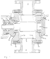
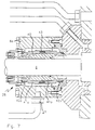
- the rotary valves shown in the drawings each consist of a housing 1 with cylindrical Interior 2, a top inlet opening 3 and one underside outlet opening 4.
- the housing 1 is with side covers 5a and 5b closed on the bearing cover 6a and 6b sit.
- Bearings 7a are located in the side covers and 7b for a shaft 8 with cellular wheel webs 9, which are extend between side windows 10a and 10b.
- the bearings 7a and 7b are located as close as possible in the side covers the side windows 10a and 10b so that the shaft 8 between the camps can be kept as short as possible in order to large pressure differences between the inlet and / or the Outlet opening and / or the environment the deflection of the To keep wave 8 low.
- a sealing fluid connection Seen from the housing interior 2, are located beyond the Bearing 7a two shaft seals 12a, 12b, between which a sealing fluid connection, here a sealing gas connection 13, opens. That into the bearings via the locking fluid connections 11a, 11b introduced fluid, usually in this embodiment a gas is supplied at a pressure approximately equal to that is the highest pressure in the lock.
- a gas is supplied at a pressure approximately equal to that is the highest pressure in the lock.
- sealing gas can have a pressure approximately equal to half the pressure difference between the housing interior 2 and the surrounding area.
- the shaft seals 12a, 12b each with only half of the total differential pressure claimed.
- each opens into the housing interior 2 on both sides Seal gas connection 17a and 17b.
- the pressure of the fed Sealing gas can be slightly higher than the pressure of the over the Locking fluid connectionella, 11b supplied to the bearings 7a and 7b Barrier fluid, which in this case is a liquid, in particular can be a lubricant.
- the additional Shaft seals 16a, 16b can be kept very narrow, because they are only exposed to a small differential pressure are.
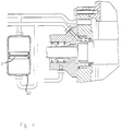
- Figure 3 shows an improved embodiment in which the Seal gas connections 11a and 17a (as well as the not shown, mirror-image sealing gas connections) from the same Source can be fed, however, only via a schematic shown filter 19 are connected to each other ensures that in the event of an unintentional reversal of the Flow direction in one or both sealing gas connections 11a and 17a no lubricants or bulk particles from one can get to the other sealing gas connection.
- the bearing 7a not with a sealing gas but with another barrier medium, e.g. a lubricant, supplied, takes the place of the filter 19 in Figure 3 is a pressure transmitting but medium separating Device, such as a pressure compensation cylinder 20 with a piston 21 slidably guided therein as in FIG 4, or a surge tank 22 with a elastic membrane 23, as shown in Figure 5, or finally, a surge tank 24, with a flexible bladder 25 as shown in Figure 6.
- a pressure transmitting but medium separating Device such as a pressure compensation cylinder 20 with a piston 21 slidably guided therein as in FIG 4, or a surge tank 22 with a elastic membrane 23, as shown in Figure 5, or finally, a surge tank 24, with a flexible bladder 25 as shown in Figure 6.
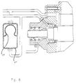
- Figure 7 shows a preferred embodiment in which the Shaft seal for the part led out of the housing the shaft 8 from a mechanical seal designated overall by 26 exists that with the barrier fluid connection 27 with is supplied with a lubricant.
- the mechanical seal 26 consists essentially of a rotatably connected to the shaft 8 base body 40, on the likewise two axially displaceable sliding rings 41a, fixed against rotation 41b are arranged which are connected via springs 43 to corresponding slip rings 42a statically mounted in the bearing cover 6a, 42b are pressed.
- Figure 8 shows a third embodiment, which differs from differs from that according to FIG. 2, for example, that widened between those in the axial direction Circumferences 10aa and 10bb of the side windows 10a and 10b and there are several ring seals 30a, 30b in the housing inner wall, the over stationary pressure disks 31a, 31b in the axial Compressed in the direction of a cloth sleeve and thereby expand radially.
- the thrust washers 31a, 31b are by means of one supplied via the connections 17a and 17b Barrier fluids, preferably a barrier gas, pressurized.
Abstract
Description
Die Erfindung betrifft eine Zellenradschleuse zum Dosieren von Schüttgut, bestehend aus einem Gehäuse mit einer oberseitigen Einlauföffnung und einer unterseitigen Auslauföffnung, sowie zwei Seitendeckeln mit Lagern für die Welle eines Seitenscheiben aufweisenden Zellenrades, sowie mit Wellendichtungen zur Abdichtung des Gehäuseinnenraums gegenüber der Umgebung.The invention relates to a rotary valve for dosing of bulk material, consisting of a housing with a top Inlet opening and an outlet opening on the underside, and two side covers with bearings for the shaft a side wheel with cellular wheel, and with Shaft seals to seal the interior of the housing against the environment.
Eine derartige Zellenradschleuse ist unter anderem aus der DE 37 42 521 C1 bekannt. Damit diese Schleuse auch bei hohen Druckdifferenzen zwischen der Einlauf- und der Auslaufseite betrieben werden kann, ist sie mit einer aufwendigen Dichtungsanordnung ausgestattet. Die Lager für die Zellenradwelle befinden sich außen in den Seitendeckeln und sind in Richtung des Schleuseninnenraums durch eine Anzahl von auf der Welle sitzenden Wellendichtungen gegen das Eindringen von insbesondere staubförmigen Schüttgutpartikeln geschützt. Diese Anordnung baut vergleichsweise breit, so daß die Zellenradwelle bei hohen Druckdifferenzen entweder eine Durchbiegung erfährt, die das betriebsmäßige Spiel auf der einen Seite vergrößert und auf der anderen Seite verkleinert, oder sehr massiv und damit biegesteif ausgeführt werden muß. Während die letztere Maßnahme ersichtlich fertigungs- und damit kostenintensiv ist, führt eine Durchbiegung der Zellenradwelle unvermeidbar zu erhöhter Reibung und damit Erwärmung sowohl im Umfangsbereich des Zellenrades als auch im Bereich der Welle und der Wellendichtungen.Such a rotary valve is, inter alia, from the DE 37 42 521 C1 known. So that this lock even at high Pressure differences between the inlet and the outlet side can be operated, it is with an expensive seal arrangement fitted. The bearings for the cellular wheel shaft are located on the outside in the side covers and are in Direction of the lock interior by a number of on the shaft seals against penetration protected from particularly dusty bulk particles. This arrangement builds comparatively wide, so that the Cellular shaft at high pressure differences either one Deflection experienced the operational play on the enlarged on one side and reduced on the other, or very solid and therefore rigid must become. While the latter measure is obviously production-intensive and therefore cost-intensive, a deflection leads the cellular wheel shaft inevitable to increased friction and thus heating both in the peripheral area of the cellular wheel and also in the area of the shaft and shaft seals.
Der Erfindung liegt die Aufgabe zugrunde, eine Zellenradschleuse der einleitend angegebenen Gattung, jedoch mit verbesserter Konstruktion zu schaffen.The invention has for its object a rotary valve the genus specified in the introduction, however with to create improved construction.
Diese Aufgabe ist erfindungsgemäß dadurch gelöst, daß mindestens eine der Wellendichtungen sich, von dem Gehäuseinnenraum gesehen, jenseits des zugehörigen, gleichseitigen Lagers befindet. Dadurch verkürzt sich die Länge der Zellenradwelle zwischen den Lagern. Die Welle wird somit ohne zusätzliche Maßnahme biegesteifer. Hierdurch werden die bei der bekannten Schleuse auftretenden Probleme beseitigt oder zumindest vermindert. Die vorgeschlagenen Schleuse kann deshalb mit einer weniger aufwendigen Dichtungsanordnung zwischen dem Zellenradumfang und der Innenwand des Schleusengehäuses auskommen und/oder problemlos unter hohen Druckdifferenzen betrieben werden. Da die Welle meist nur auf einer Seite aus dem Schleusengehäuse herausgeführt und mit einem Antrieb verbunden ist, genügt es in solchen Fällen, nur auf der mit der Umgebung kommunizierenden Seite der Zellenradwelle eine Wellendichtung vorzusehen. Diese muß selbstverständlich der auftretenden Druckdifferenz standhalten können. Der jenseits des Lagers liegende und durch den Seitendeckel hindurch herausgeführte Teil der Welle unterliegt keiner solchen Biegebeanspruchung und braucht daher nur den zur Übertragung des Drehmomentes notwendigen, in der Regel deutlich kleineren Durchmesser zu haben. Auf diesem kleineren Durchmesser sitzt die Wellendichtung. Entsprechend kleiner ist im Vergleich zu der bisherigen Konstruktion das Reibmoment und damit auch die Reibungswärme. Diese entsteht zudem in einem relativ großen Abstand von dem Zellenrad. Ein weiterer Vorteil der vorge- schlagenen Anordnung der Wellendichtung oder -dichtungen jenseits des zugehörigen Lagers besteht darin, daß deren Breite keinerlei Einfluß auf die unterstützte Länge der Welle zwischen den Lagern hat und deshalb Wellendichtungen beliebigen, geeigneten Typs verwendet werden können, so daß auch die Erzielung der notwendigen Druckdifferenzfestigkeit keine Schwierigkeiten bereitet. This object is achieved in that at least one of the shaft seals itself, from the housing interior seen, beyond the associated, equilateral Camp is located. This shortens the length of the cellular wheel shaft between the camps. The wave is therefore without additional measure more rigid. As a result, the the known lock problems encountered or at least diminished. The proposed lock can therefore with a less complex seal arrangement between the cell wheel circumference and the inner wall of the lock housing get along and / or easily under high pressure differences operate. Since the wave is mostly only on one side out of the lock housing and with is connected to a drive, in such cases it is sufficient only on the side of the To provide a rotary shaft seal for the cellular wheel shaft. This must of course withstand the occurring pressure difference can. The one beyond the camp and through the Part of the shaft led out through the side cover is subject to no such bending stress and therefore needs only those necessary for the transmission of the torque in the Usually have a much smaller diameter. On this the shaft seal is smaller in diameter. Corresponding that is smaller compared to the previous construction Frictional moment and thus also the frictional heat. This arises also at a relatively large distance from the cellular wheel. A Another advantage of the proposed arrangement of the shaft seal or seals beyond the associated bearing is that their width does not affect the supported length of the shaft between the bearings and therefore shaft seals of any suitable type are used can be, so that the achievement of the necessary Differential pressure resistance is no problem.
Sofern die Gefahr besteht, daß Schüttgutpartikel in das Lager eindringen, kann in an sich bekannter Weise im Bereich des Lager ein Sperrfluidanschluß münden (Anspruch 2). Über diesen kann ein Sperrgas oder eine Sperrflüssigkeit, bedarfsweise auch ein Schmiermittel, zugeführt werden.If there is a risk that bulk particles in the Bearing can penetrate in a known manner in the area the bearing open a barrier fluid connection (claim 2). over This can be a sealing gas or a sealing liquid, if necessary also a lubricant.
Stattdessen oder zusätzlich kann sich zwischen mindestens einer der Seitenscheiben und dem gleichseitigen Lager mindestens eine dritte Wellendichtung befinden (Anspruch 3). Diese Wellendichtung braucht dann auch bei hohem Differenzdruck zwischen dem Gehäuseinnenraum und der Umgebung nur eine geringe Differenzdruckfestigkeit aufzuweisen, da die jenseits des betreffenden Lagers außen angeordnete Wellendichtung, gegebenenfalls unterstützt durch eine Sperrgaszufuhr, den größten Teil des Differenzdruckes aufnimmt.Instead, or in addition, you can choose between at least at least one of the side windows and the equilateral bearing are a third shaft seal (claim 3). This shaft seal then also needs a high differential pressure between the housing interior and the environment only to have a low differential pressure resistance because the shaft seal located outside the bearing in question, possibly supported by a sealing gas supply, absorbs most of the differential pressure.
Vor allem wenn die Gefahr besteht, daß das über den Sperrfluidanschluß eingeleitete Medium z.B. während des Anfahrens oder Stillsetzens der Schleuse Schmiermittel aus dem Lager in den Gehäuseinnenraum trägt, kann mindestens in den Raum zwischen einer der Seitenscheiben und dem gleichseitigen Seitendeckel ein Sperrgasanschluß münden (Anspruch 4).Especially when there is a risk that this is via the barrier fluid connection introduced medium e.g. during start-up or shutting down the lock of lubricant from the bearing in the interior of the case, at least in the room between one of the side windows and the equilateral Side cover open a sealing gas connection (claim 4).
Der Sperrfluidanschluß und der Sperrgasanschluß können unter Umständen aus einer gemeinsamen Sperrgasquelle gespeist werden, jedoch ist es dann zweckmäßig, wenn der Sperrfluidanschluß über ein Filter mit dem Sperrgasanschluß verbunden ist (Anspruch 5). Hierdurch wird auch bei einer Richtungsumkehr der Fluidströmung z.B. in dem ersten Anschluß, wie sie insbesondere beim Anfahren, beim Stillsetzen oder bei einer Betriebsstörung der Schleuse oder des Fördervorganges eintreten kann, verhindert, daß beispielsweise Schmiermittel aus dem Lager über dessen Sperrfluidanschluß, den gemeinsamen Anschluß an die Sperrgasquelle und den in den Innenraum mündenden Sperrgasanschluß in die Schleuse gelangen kann.The sealing fluid connection and the sealing gas connection can be under Circumstances are fed from a common sealing gas source, however, it is then expedient if the barrier fluid connection connected to the sealing gas connection via a filter is (claim 5). This will also change direction the fluid flow e.g. in the first port, like especially when starting, stopping or at a malfunction of the lock or the conveying process can occur, prevents, for example, lubricants from the camp through its barrier fluid connection, the common Connection to the sealing gas source and to the interior can reach the lock gas outlet into the lock.
Stattdessen können auch der Sperrfluidanschluß und der Sperrgasanschluß an getrennte Quellen angeschlossen, jedoch über eine mediumstrennende Druckausgleichsvorrichtung miteinander verbunden sein (Anspruch 6).Instead, the barrier fluid connection and the Purge gas connector connected to separate sources, however with each other via a medium-separating pressure compensation device be connected (claim 6).
Die Druckausgleichsvorrichtung kann ein in einem Zylinder verschiebbarer Kolben (Anspruch 7), ein durch eine elastische Membran geteiltes Druckausgleichsgefäß (Anspruch 8) oder ein durch eine elastische Blase geteiltes Druckausgleichsgefäß (Anspruch 9) sein.The pressure compensation device can be in a cylinder displaceable piston (claim 7), one by an elastic Membrane divided pressure compensation vessel (claim 8) or a pressure compensation vessel divided by an elastic bladder (Claim 9).
Wie bereits erwähnt, hat der Vorschlag nach der Erfindung u.a. den Vorteil, nahezu beliebige, im erforderlichen Maß druckdifferenzfeste Wellendichtungen einsetzen zu können. In diesem Sinne kann die mindestens eine Wellendichtung eine Gleitringdichtung sein, in die ein weiterer Sperrfluidanschluß mündet (Anspruch 10). Als Sperrfluid wird für solche an sich bekannten Gleitringdichtungen meist ein flüssiges Medium eingesetzt.As already mentioned, the proposal according to the invention i.a. the advantage, almost any, to the extent necessary to be able to use pressure differential resistant shaft seals. In In this sense, the at least one shaft seal can Mechanical seal, in which another barrier fluid connection opens (claim 10). As a barrier fluid for such mechanical seals known per se mostly a liquid Medium used.
Stattdessen können sich, von dem Gehäuseinnenraum gesehen, mindestens zwei konventionelle Wellendichtungen jenseits des zugehörigen gleichseitigen Lagers befinden, wobei dann in den Raum zwischen den beiden Wellendichtungen ein weiterer Sperrgasanschluß mündet (Anspruch 11), über den das Sperrgas mit einem Druck zugeführt wird, der einen Abbau des Drucks im Gehäuseinnenraum auf den Umgebungsdruck in vorgegebenen, z.B. gleichen Druckstufen, gewährleistet, so daß beide Wellendichtungen lediglich für den halben Differenzdruck ausgelegt zu sein brauchen.Instead, as seen from the housing interior, at least two conventional shaft seals beyond the associated equilateral bearing are located, then in the space between the two shaft seals is another The sealing gas connection opens (claim 11), via which the sealing gas is supplied with a pressure that causes a decrease in pressure in the housing interior to the ambient pressure in predetermined, e.g. same pressure levels, so that both shaft seals only designed for half the differential pressure need to be.
Um das oder die Lager und, sofern vorhanden, die jeweilige dritte Wellendichtung zwischen dem Lager und der gleichseitigen Seitenscheibe noch besser gegen das Eindringen von Schüttgutpartikeln zu schützen, kann sich zwischen den Umfängen der Seitenscheiben und der Gehäuseinnenwand eine die entsprechenden Ringspalte abdichtende Ringdichtung befinden. Hierfür sind verschiedene Lösungen im Stand der Technik bekannt.To the camp or camp and, if available, the respective third shaft seal between the bearing and the equilateral Side window even better against the ingress of Protecting bulk particles can vary between the Circumferences of the side windows and the inner wall of the housing the corresponding ring gap sealing ring seal are located. Various solutions are available for this Technology known.
In der Zeichnung ist die Zellenradschleuse nach der Erfindung in mehreren Ausführungsbeispielen schematisch vereinfacht dargestellt. Es zeigt:
- Fig. 1
- eine erste Ausführungsform im Längsschnitt
- Fig. 2
- eine zweite Ausführungsform im Längsschnitt
- Fig. 3 bis 7
- unterschiedliche Weiterbildungen der zweiten Ausführungsform im Ausschnitt und
- Fig. 8
- eine dritte Ausführungsform im Längsschnitt.
- Fig. 1
- a first embodiment in longitudinal section
- Fig. 2
- a second embodiment in longitudinal section
- 3 to 7
- different developments of the second embodiment in the detail and
- Fig. 8
- a third embodiment in longitudinal section.
Die in den Zeichnungen dargestellten Zellenradschleusen
bestehen jeweils aus einem Gehäuse 1 mit zylindrischen
Innenraum 2, einer oberseitigen Einlauföffnung 3 und einer
unterseitigen Auslauföffnung 4. Das Gehäuse 1 ist mit Seitendeckeln
5a und 5b verschlossen auf denen Lagerdeckel 6a
und 6b sitzen. In den Seitendeckeln befinden sich Lager 7a
und 7b für eine Welle 8 mit Zellenradstegen 9, die sich
zwischen Seitenscheiben 10a und 10b erstrecken. Die Lager 7a
und 7b befinden sich in den Seitendeckeln möglichst nahe an
den Seitenscheiben 10a und 10b, damit die Welle 8 zwischen
den Lagern möglichst kurz gehalten werden kann, um auch bei
großen Druckdifferenzen zwischen der Einlauf- und/oder der
Auslauföffnung und/oder der Umgebung die Durchbiegung der
Welle 8 gering zu halten.The rotary valves shown in the drawings
each consist of a housing 1 with
In der Ausführungsform nach Figur 1 mündet in den Bereich
der Lager 7a und 7b je ein Sperrfluidanschluß 11a und 11b. In the embodiment of Figure 1 opens into the area
the bearings 7a and 7b each have a
Vom Gehäuseinnenraum 2 gesehen, befinden sich jenseits des
Lagers 7a zwei Wellendichtungen 12a, 12b, zwischen denen
ein Sperrfluidanschluß, hier ein Sperrgasanschluß 13, mündet.
Das über die Sperrfluidanschlüsse 11a, 11b in die Lager
eingeleitete Fluid, in der Regel bei dieser Ausführungsform
ein Gas, wird mit einem Druck zugeführt, der etwa gleich dem
höchsten in der Schleuse herrschenden Druck ist. Das über
den Sperrgasanschluß 13 den Wellendichtungen zugeführte
Sperrgas kann hingegen einen Druck etwa gleich der Hälfte
des Druckunterschiedes zwischen dem Gehäuseinnenraum 2 und
der Umgebung haben. In diesem Fall werden die Wellendichtungen
12a, 12b jeweils nur mit der Hälfte des gesamten Differenzdruckes
beansprucht.Seen from the
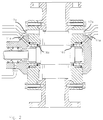
In der Ausführungsform gemäß Figur 2 befinden sich auf der
Welle 8 zwischen dem Gehäuseinnenraum 2 und dem jeweiligen
Lager 7a und 7b zusätzliche Wellendichtungen 16a und 16b.
Außerdem mündet in den Gehäuseinnenraum 2 beidseits je ein
Sperrgasanschluß 17a und 17b. Der Druck des zugeführten
Sperrgases kann etwas höher als der Druck des über die
Sperrfluidanschlüssella, 11b den Lagern 7a und 7b zugeführten
Sperrfluids sein, das in diesem Fall eine Flüssigkeit,
insbesondere ein Schmiermittel sein kann. Die zusätzlichen
Wellendichtungen 16a, 16b können sehr schmal gehalten werden,
weil sie nur einem geringen Differenzdruck ausgesetzt
sind.In the embodiment according to Figure 2 are on the
Figur 3 zeigt eine verbesserte Ausführungsform, bei der die
Sperrgasanschlüsse 11a und 17a (sowie die nicht dargestellten,
spiegelbildlichen Sperrgasanschlüsse) aus der gleichen
Quelle gespeist werden, jedoch über ein nur schematisch
dargestelltes Filter 19 miteinander verbunden sind, das
dafür sorgt, daß bei einer unbeabsichtigten Umkehr der
Strömungsrichtung in einem oder beiden Sperrgasanschlüssen
11a und 17a keine Schmiermittel oder Schüttgutpartikel von
dem einen zu dem anderen Sperrgasanschluß gelangen können. Figure 3 shows an improved embodiment in which the
Wird hingegen z.B. das Lager 7a nicht mit einem Sperrgas
sondern mit einem anderen Sperrmedium, z.B. einem Schmiermittel,
versorgt, so tritt an die Stelle des Filters 19 in
Figur 3 eine druckübertragende jedoch mediumstrennende
Vorrichtung, wie etwa ein Druckausgleichszylinder 20 mit
einem darin verschieblich geführten Kolben 21 wie in Figur
4 dargestellt, oder ein Druckausgleichsbehälter 22 mit einer
elastischen Membran 23, wie in Figur 5 dargestellt, oder
schließlich auch ein Druckausgleichsbehälter 24, mit einer
flexiblen Blase 25, wie in Figur 6 dargestellt.However, if e.g. the bearing 7a not with a sealing gas
but with another barrier medium, e.g. a lubricant,
supplied, takes the place of the
Figur 7 zeigt eine bevorzugte Ausführungsform, in der die
Wellendichtung für den aus dem Gehäuse herausgeführten Teil
der Welle 8 aus einer insgesamt mit 26 bezeichneten Gleitringdichtung
besteht, die über den Sperrfluidanschluß 27 mit
einem Schmiermittel versorgt wird.Figure 7 shows a preferred embodiment in which the
Shaft seal for the part led out of the housing
the
Die Gleitringdichtung 26 besteht im wesentlichen aus einem
drehfest mit der Welle 8 verbundenen Grundkörper 40, auf dem
ebenfalls drehfest zwei axial verschiebbare Gleitringe 41a,
41b angeordnet sind, die über Federn 43 auf korrespondierende,
statisch im Lagerdeckel 6a montierte Gleitringe 42a,
42b gepreßt werden.The
Figur 8 zeigt eine dritte Ausführungsform, die sich von
derjenigen beispielsweise nach Figur 2 dadurch unterscheidet,
daß sich zwischen den in axialer Richtung verbreiterten
Umfängen 10aa bzw. 10bb der Seitenscheiben 10a und 10b und
der Gehäuseinnenwand mehrere Ringdichtungen 30a, 30b befinden,
die über stillstehende Druckscheiben 31a, 31b in axialer
Richtung stoffbüchsenartig komprimiert werden und dadurch
radial expandieren. Die Druckscheiben 31a, 31b sind
mittels eines über die Anschlüsse 17a und 17b zugeführten
Sperrfluides, vorzugsweise eines Sperrgases, druckbeaufschlagt.Figure 8 shows a third embodiment, which differs from
differs from that according to FIG. 2, for example,
that widened between those in the axial direction
Circumferences 10aa and 10bb of the
Claims (12)
Applications Claiming Priority (2)
| Application Number | Priority Date | Filing Date | Title |
|---|---|---|---|
| DE19738122A DE19738122A1 (en) | 1997-09-01 | 1997-09-01 | Cell wheel lock for dosing bulk goods |
| DE19738122 | 1997-09-01 |
Publications (2)
| Publication Number | Publication Date |
|---|---|
| EP0899223A1 true EP0899223A1 (en) | 1999-03-03 |
| EP0899223B1 EP0899223B1 (en) | 2002-11-27 |
Family
ID=7840830
Family Applications (1)
| Application Number | Title | Priority Date | Filing Date |
|---|---|---|---|
| EP98114336A Expired - Lifetime EP0899223B1 (en) | 1997-09-01 | 1998-07-30 | Cellular-wheel lock for dosing bulk material |
Country Status (5)
| Country | Link |
|---|---|
| US (1) | US6129246A (en) |
| EP (1) | EP0899223B1 (en) |
| JP (1) | JPH11130264A (en) |
| AT (1) | ATE228471T1 (en) |
| DE (2) | DE19738122A1 (en) |
Cited By (1)
| Publication number | Priority date | Publication date | Assignee | Title |
|---|---|---|---|---|
| EP3456665A1 (en) * | 2017-04-28 | 2019-03-20 | Rombold & Gfröhrer GmbH & Co. KG | Cellular rotary feeder |
Families Citing this family (8)
| Publication number | Priority date | Publication date | Assignee | Title |
|---|---|---|---|---|
| US7626143B2 (en) * | 2005-02-17 | 2009-12-01 | Scott Richard Miller | Apparatus and method for processing hot melt adhesives |
| US20080260539A1 (en) * | 2005-10-07 | 2008-10-23 | Aker Kvaerner Subsea As | Apparatus and Method For Controlling Supply of Barrier Gas in a Compressor Module |
| US8651772B2 (en) * | 2007-12-20 | 2014-02-18 | General Electric Company | Rotary apparatus for use with a gasifier system and methods of using the same |
| DE102009053360B4 (en) * | 2009-11-17 | 2012-03-22 | Ksb Aktiengesellschaft | Mechanical seal assembly for high peripheral speeds |
| DE202010012138U1 (en) * | 2010-09-02 | 2011-12-12 | Hermann Linder | rotary |
| DE102012206590A1 (en) * | 2012-04-20 | 2013-10-24 | Coperion Gmbh | Method for operating a rotary valve and rotary valve for performing the method |
| US20140119881A1 (en) * | 2012-10-31 | 2014-05-01 | General Electric Company | Apparatus for recirculating a fluid within a turbomachine and method for operating the same |
| US10520035B2 (en) * | 2016-11-04 | 2019-12-31 | United Technologies Corporation | Variable volume bearing compartment |
Citations (4)
| Publication number | Priority date | Publication date | Assignee | Title |
|---|---|---|---|---|
| DE3339061A1 (en) * | 1982-10-30 | 1984-05-03 | Bergwerksverband Gmbh, 4300 Essen | Cellular-wheel sluice |
| DE3521194A1 (en) * | 1985-06-13 | 1986-12-18 | Ibau Hamburg Ingenieurgesellschaft Industriebau Mbh, 2000 Hamburg | Apparatus for feeding in dust-like material |
| DE3742522C1 (en) * | 1987-12-15 | 1988-11-03 | Waeschle Maschf Gmbh | Cell wheel lock |
| EP0586728A1 (en) * | 1992-09-09 | 1994-03-16 | Societe Des Produits Nestle S.A. | Rotary valve |
Family Cites Families (11)
| Publication number | Priority date | Publication date | Assignee | Title |
|---|---|---|---|---|
| US3151784A (en) * | 1961-10-24 | 1964-10-06 | John P Tailor | Rotary air lock |
| US3260420A (en) * | 1964-07-28 | 1966-07-12 | Richards Structural Steel Comp | Motor driven rotary dispensing valve |
| DD208052A3 (en) * | 1982-03-08 | 1984-03-21 | Freiberg Brennstoffinst | SEALING SYSTEM ON WAVES AGAINST STRONG SLIPPING, GASOFUL, COMPRESSED MEDIA |
| DD279374A3 (en) * | 1984-03-20 | 1990-06-06 | Orgreb Inst Kraftwerke | METHOD AND DEVICE FOR PREVENTING ATTACHMENTS IN CELL WHEEL BARS |
| US4722663A (en) * | 1986-02-04 | 1988-02-02 | Rotoflow Corporation | Seal-off mechanism for rotating turbine shaft |
| DE3742521C1 (en) * | 1987-12-15 | 1989-04-13 | Waeschle Maschf Gmbh | Cell wheel lock |
| DE4019627C3 (en) * | 1990-06-20 | 1998-04-23 | Motan Fuller Verfahrenstechnik | Housing for a rotary valve |
| DE4244655C2 (en) * | 1992-05-06 | 2000-05-31 | Reimelt Dietrich Kg | Cell wheel lock |
| AT401042B (en) * | 1992-11-23 | 1996-05-28 | Naintsch Mineralwerke | DEVICE FOR SEALING THE ROTOR SHAFT HOUSING THROUGH A PRESSURE-SEALED CELL WHEEL LOCK |
| CA2167424C (en) * | 1995-02-02 | 2002-02-19 | David C. Orlowski | Emission seal |
| DE29600707U1 (en) * | 1996-01-17 | 1996-03-07 | Burgmann Dichtungswerk Feodor | Sealing arrangement |
-
1997
- 1997-09-01 DE DE19738122A patent/DE19738122A1/en not_active Withdrawn
-
1998
- 1998-07-30 AT AT98114336T patent/ATE228471T1/en not_active IP Right Cessation
- 1998-07-30 DE DE59806413T patent/DE59806413D1/en not_active Expired - Lifetime
- 1998-07-30 EP EP98114336A patent/EP0899223B1/en not_active Expired - Lifetime
- 1998-08-24 US US09/138,432 patent/US6129246A/en not_active Expired - Fee Related
- 1998-08-31 JP JP10245964A patent/JPH11130264A/en not_active Withdrawn
Patent Citations (4)
| Publication number | Priority date | Publication date | Assignee | Title |
|---|---|---|---|---|
| DE3339061A1 (en) * | 1982-10-30 | 1984-05-03 | Bergwerksverband Gmbh, 4300 Essen | Cellular-wheel sluice |
| DE3521194A1 (en) * | 1985-06-13 | 1986-12-18 | Ibau Hamburg Ingenieurgesellschaft Industriebau Mbh, 2000 Hamburg | Apparatus for feeding in dust-like material |
| DE3742522C1 (en) * | 1987-12-15 | 1988-11-03 | Waeschle Maschf Gmbh | Cell wheel lock |
| EP0586728A1 (en) * | 1992-09-09 | 1994-03-16 | Societe Des Produits Nestle S.A. | Rotary valve |
Cited By (1)
| Publication number | Priority date | Publication date | Assignee | Title |
|---|---|---|---|---|
| EP3456665A1 (en) * | 2017-04-28 | 2019-03-20 | Rombold & Gfröhrer GmbH & Co. KG | Cellular rotary feeder |
Also Published As
| Publication number | Publication date |
|---|---|
| US6129246A (en) | 2000-10-10 |
| DE59806413D1 (en) | 2003-01-09 |
| EP0899223B1 (en) | 2002-11-27 |
| ATE228471T1 (en) | 2002-12-15 |
| JPH11130264A (en) | 1999-05-18 |
| DE19738122A1 (en) | 1999-03-11 |
Similar Documents
| Publication | Publication Date | Title |
|---|---|---|
| DE4115626C2 (en) | Rod seal | |
| EP2013519B1 (en) | Sealing arrangement | |
| DE602005004001T2 (en) | Device for carrying and guiding a rotating shaft | |
| CH678093A5 (en) | ||
| DE3537822C2 (en) | ||
| DE2135344B2 (en) | Device for sealing and mounting the shaft passing through a machine housing | |
| DE2403925A1 (en) | SEALING DEVICE FOR SHAFT OUTPUTS OF MACHINERY | |
| DE2811020A1 (en) | MECHANICAL-HYDRAULIC DEVICE FOR BRAKING A LOAD SUBJECTED TO SHOCKS AND VIBRATIONS | |
| DE2101877A1 (en) | Mechanical seal | |
| DE4107586C1 (en) | ||
| DE4005428A1 (en) | LOCKING FLUID SEAL ARRANGEMENT IN A TURBO COMPRESSOR | |
| EP0899223A1 (en) | Cellular-wheel lock for dosing bulk material | |
| DE60104329T2 (en) | SHAFT SEAL | |
| EP0605471A1 (en) | Swash pump. | |
| DE60027624T2 (en) | Shaft seal arrangement for concrete or mortar mixers | |
| DE3343938A1 (en) | BEARING SEAL FOR A CENTRIFUGE | |
| DE3220595C2 (en) | ||
| DE69631307T2 (en) | scroll compressor | |
| DE3612495A1 (en) | THRUST BEARING / SEAL ARRANGEMENT | |
| DE2842734B1 (en) | Rotary slide valve, in particular for a hydrostatic power steering device | |
| DE2746592A1 (en) | Seal for ship's propeller shaft - has two axially spaced lips controlled by lubricant at pressure greater than water pressure | |
| DE3426705C2 (en) | Sealing arrangement for blocking a shaft or shaft passage | |
| DE19901967A1 (en) | Cell wheel lock for transporting or dosing bulk material has cell wheel supported on radially outward-lying elements of two ring elements per bearing arrangement | |
| DE1750522B1 (en) | NON-CONTACT SEAL | |
| DE3722862A1 (en) | Rotational viscometer for determining the viscosity of flowable media |
Legal Events
| Date | Code | Title | Description |
|---|---|---|---|
| PUAI | Public reference made under article 153(3) epc to a published international application that has entered the european phase |
Free format text: ORIGINAL CODE: 0009012 |
|
| AK | Designated contracting states |
Kind code of ref document: A1 Designated state(s): AT BE CH DE ES FI FR GB IT LI NL SE |
|
| AX | Request for extension of the european patent |
Free format text: AL;LT;LV;MK;RO;SI |
|
| 17P | Request for examination filed |
Effective date: 19990318 |
|
| RAP1 | Party data changed (applicant data changed or rights of an application transferred) |
Owner name: WAESCHLE GMBH |
|
| AKX | Designation fees paid |
Free format text: AT BE CH DE ES FI FR GB IT LI NL SE |
|
| 17Q | First examination report despatched |
Effective date: 19991202 |
|
| RAP1 | Party data changed (applicant data changed or rights of an application transferred) |
Owner name: COPERION WAESCHLE GMBH & CO. KG |
|
| GRAG | Despatch of communication of intention to grant |
Free format text: ORIGINAL CODE: EPIDOS AGRA |
|
| GRAG | Despatch of communication of intention to grant |
Free format text: ORIGINAL CODE: EPIDOS AGRA |
|
| GRAH | Despatch of communication of intention to grant a patent |
Free format text: ORIGINAL CODE: EPIDOS IGRA |
|
| GRAH | Despatch of communication of intention to grant a patent |
Free format text: ORIGINAL CODE: EPIDOS IGRA |
|
| GRAA | (expected) grant |
Free format text: ORIGINAL CODE: 0009210 |
|
| AK | Designated contracting states |
Kind code of ref document: B1 Designated state(s): AT BE CH DE ES FI FR GB IT LI NL SE |
|
| PG25 | Lapsed in a contracting state [announced via postgrant information from national office to epo] |
Ref country code: NL Free format text: LAPSE BECAUSE OF FAILURE TO SUBMIT A TRANSLATION OF THE DESCRIPTION OR TO PAY THE FEE WITHIN THE PRESCRIBED TIME-LIMIT Effective date: 20021127 Ref country code: IT Free format text: LAPSE BECAUSE OF FAILURE TO SUBMIT A TRANSLATION OF THE DESCRIPTION OR TO PAY THE FEE WITHIN THE PRESCRIBED TIME-LIMIT;WARNING: LAPSES OF ITALIAN PATENTS WITH EFFECTIVE DATE BEFORE 2007 MAY HAVE OCCURRED AT ANY TIME BEFORE 2007. THE CORRECT EFFECTIVE DATE MAY BE DIFFERENT FROM THE ONE RECORDED. Effective date: 20021127 Ref country code: GB Free format text: LAPSE BECAUSE OF FAILURE TO SUBMIT A TRANSLATION OF THE DESCRIPTION OR TO PAY THE FEE WITHIN THE PRESCRIBED TIME-LIMIT Effective date: 20021127 Ref country code: FI Free format text: LAPSE BECAUSE OF FAILURE TO SUBMIT A TRANSLATION OF THE DESCRIPTION OR TO PAY THE FEE WITHIN THE PRESCRIBED TIME-LIMIT Effective date: 20021127 |
|
| REF | Corresponds to: |
Ref document number: 228471 Country of ref document: AT Date of ref document: 20021215 Kind code of ref document: T |
|
| REG | Reference to a national code |
Ref country code: GB Ref legal event code: FG4D Free format text: NOT ENGLISH |
|
| REG | Reference to a national code |
Ref country code: CH Ref legal event code: EP |
|
| REF | Corresponds to: |
Ref document number: 59806413 Country of ref document: DE Date of ref document: 20030109 |
|
| ET | Fr: translation filed | ||
| PG25 | Lapsed in a contracting state [announced via postgrant information from national office to epo] |
Ref country code: SE Free format text: LAPSE BECAUSE OF FAILURE TO SUBMIT A TRANSLATION OF THE DESCRIPTION OR TO PAY THE FEE WITHIN THE PRESCRIBED TIME-LIMIT Effective date: 20030227 |
|
| NLV1 | Nl: lapsed or annulled due to failure to fulfill the requirements of art. 29p and 29m of the patents act | ||
| GBV | Gb: ep patent (uk) treated as always having been void in accordance with gb section 77(7)/1977 [no translation filed] |
Effective date: 20021127 |
|
| PG25 | Lapsed in a contracting state [announced via postgrant information from national office to epo] |
Ref country code: ES Free format text: LAPSE BECAUSE OF FAILURE TO SUBMIT A TRANSLATION OF THE DESCRIPTION OR TO PAY THE FEE WITHIN THE PRESCRIBED TIME-LIMIT Effective date: 20030529 |
|
| PG25 | Lapsed in a contracting state [announced via postgrant information from national office to epo] |
Ref country code: AT Free format text: LAPSE BECAUSE OF NON-PAYMENT OF DUE FEES Effective date: 20030730 |
|
| PG25 | Lapsed in a contracting state [announced via postgrant information from national office to epo] |
Ref country code: LI Free format text: LAPSE BECAUSE OF NON-PAYMENT OF DUE FEES Effective date: 20030731 Ref country code: CH Free format text: LAPSE BECAUSE OF NON-PAYMENT OF DUE FEES Effective date: 20030731 Ref country code: BE Free format text: LAPSE BECAUSE OF NON-PAYMENT OF DUE FEES Effective date: 20030731 |
|
| PLBE | No opposition filed within time limit |
Free format text: ORIGINAL CODE: 0009261 |
|
| STAA | Information on the status of an ep patent application or granted ep patent |
Free format text: STATUS: NO OPPOSITION FILED WITHIN TIME LIMIT |
|
| 26N | No opposition filed |
Effective date: 20030828 |
|
| BERE | Be: lapsed |
Owner name: *COPERION WAESCHLE G.M.B.H. & CO. K.G. Effective date: 20030731 |
|
| REG | Reference to a national code |
Ref country code: CH Ref legal event code: PL |
|
| PG25 | Lapsed in a contracting state [announced via postgrant information from national office to epo] |
Ref country code: FR Free format text: LAPSE BECAUSE OF NON-PAYMENT OF DUE FEES Effective date: 20040331 |
|
| REG | Reference to a national code |
Ref country code: FR Ref legal event code: ST |
|
| REG | Reference to a national code |
Ref country code: DE Ref legal event code: R082 Ref document number: 59806413 Country of ref document: DE Representative=s name: RAU, SCHNECK & HUEBNER PATENTANWAELTE RECHTSAN, DE Ref country code: DE Ref legal event code: R082 Ref document number: 59806413 Country of ref document: DE Representative=s name: RAU, SCHNECK & HUEBNER PATENT- UND RECHTSANWAE, DE |
|
| PGFP | Annual fee paid to national office [announced via postgrant information from national office to epo] |
Ref country code: DE Payment date: 20130924 Year of fee payment: 16 |
|
| REG | Reference to a national code |
Ref country code: DE Ref legal event code: R119 Ref document number: 59806413 Country of ref document: DE |
|
| PG25 | Lapsed in a contracting state [announced via postgrant information from national office to epo] |
Ref country code: DE Free format text: LAPSE BECAUSE OF NON-PAYMENT OF DUE FEES Effective date: 20150203 |
|
| REG | Reference to a national code |
Ref country code: DE Ref legal event code: R119 Ref document number: 59806413 Country of ref document: DE Effective date: 20150203 |