EP0899094A2 - Procédé et appareil d'impression par électrocoagulation multicolore - Google Patents
Procédé et appareil d'impression par électrocoagulation multicolore Download PDFInfo
- Publication number
- EP0899094A2 EP0899094A2 EP98116247A EP98116247A EP0899094A2 EP 0899094 A2 EP0899094 A2 EP 0899094A2 EP 98116247 A EP98116247 A EP 98116247A EP 98116247 A EP98116247 A EP 98116247A EP 0899094 A2 EP0899094 A2 EP 0899094A2
- Authority
- EP
- European Patent Office
- Prior art keywords
- colloid
- positive electrode
- belt
- electrode active
- onto
- Prior art date
- Legal status (The legal status is an assumption and is not a legal conclusion. Google has not performed a legal analysis and makes no representation as to the accuracy of the status listed.)
- Granted
Links
Images


Classifications
-
- B—PERFORMING OPERATIONS; TRANSPORTING
- B41—PRINTING; LINING MACHINES; TYPEWRITERS; STAMPS
- B41C—PROCESSES FOR THE MANUFACTURE OR REPRODUCTION OF PRINTING SURFACES
- B41C1/00—Forme preparation
- B41C1/10—Forme preparation for lithographic printing; Master sheets for transferring a lithographic image to the forme
- B41C1/105—Forme preparation for lithographic printing; Master sheets for transferring a lithographic image to the forme by electrocoagulation, by electro-adhesion or by electro-releasing of material, e.g. a liquid from a gel
Definitions
- the present invention pertains to improvements in the field of dynamic printing. More particularly, the invention relates to an improved multicolor electrocoagulation printing method and apparatus.
- the positive electrode is coated with a dispersion containing an olefinic substance and a metal oxide prior to electrical energization of the negative electrodes in order to weaken the adherence of the dots of coagulated colloid to the positive electrode and also to prevent an uncontrolled corrosion of the positive electrode.
- gas generated as a result of electrolysis upon energizing the negative electrodes is consumed by reaction with the olefinic substance so that there is no gas accumulation between the negative and positive electrodes.
- the electrocoagulation printing ink which is injected into the gap defined between the positive and negative electrodes consists essentially of a liquid colloidal dispersion containing an electrolytically coagulable colloid, a dispersing medium, a soluble electrolyte and a coloring agent.
- the coloring agent used is a pigment
- a dispersing agent is added for uniformly dispersing the pigment into the ink.
- any remaining non-coagulated colloid is removed from the surface of the positive electrode, for example, by scraping the surface with a soft rubber squeegee, so as to fully uncover the colored, coagulated colloid which is thereafter transferred onto the substrate.
- the surface of the positive electrode is thereafter cleaned by means of a plurality of rotating brushes and a cleaning liquid to remove any residual coagulated colloid adhered to the surface of the positive electrode.
- the negative electrodes, the positive electrode coating device, ink injector, rubber squeegee and positive electrode cleaning device are arranged to define a printing unit and several printing units each using a coloring agent of different color are disposed around the positive cylindrical electrode to produce several differently colored images of coagulated colloid which are transferred at respective transfer stations from the positive electrode active surface onto the substrate in superimposed relation to provide the desired polychromic image.
- the substrate which is in the form of a continuous web is partially wrapped around the positive electrode and passed through the respective transfer stations for being imprinted with the differently colored images in superimposed relation.
- the paper web Since the paper web is brought into contact with the dots of colored, coagulated colloid produced by each printing unit, by the positive cylindrical electrode upon rotation thereof and pressed against the positive electrode active surface by pressure rollers for being imprinted with differently colored images of coagulated colloid, the web is often displaced between the positive electrode and the pressure rollers in a direction parallel to the longitudinal axis of the positive electrode. Accordingly, it is difficult to provide a polychromic image in which the differently colored images are perfectly superimposed.
- a multicolor electrocoagulation printing method comprising the steps of:
- the present invention also provides, in a further aspect thereof, an apparatus for carrying out a method as defined above.
- the apparatus of the invention comprises:
- the inventor has found quite unexpectedly that by utilizing an endless non-extendable belt having a colloid retaining surface such as a porous surface on which dots of colored, coagulated colloid can be transferred and by moving such a belt independently of the positive electrode, from one printing unit to another, so that the colloid retaining surface of the belt contacts the colored, coagulated colloid in sequence, it is possible to significantly improve the registration of the differently colored images upon their transfer onto the colloid retaining surface of the belt, thereby providing a polychromic image of high definition which can thereafter be transferred onto the paper web or other substrate.
- a belt comprising a plastic material having a porous coating of silica.
- the positive electrode used can be in the form of a moving endless belt as described in the inventor's US Patent No. 4,661,222, or in the form of a revolving cylinder as described in the inventor's US Patent No. 4,895,629 or in the aforementioned US Patent No. 5,538,601, the teachings of which are incorporated herein by reference.
- the printing units are arranged around the positive cylindrical electrode.
- the positive electrode active surface and the ink are maintained at a temperature of about 35-60°C, preferably 40°C, to increase the viscosity of the coagulated colloid in step (b) so that the dots of colored, coagulated colloid remain coherent during their transfer in step (c), thereby enhancing transfer of the colored, coagulated colloid onto the substrate.
- the positive electrode active surface can be heated at the desired temperature and the ink applied on the heated electrode surface to cause a transfer of heat therefrom to the ink.
- step (b) of the above electrocoagulation printing method is carried out by:
- suitable electrolytically inert metals from which the positive and negative electrodes can be made are stainless steel, platinum, chromium, nickel and aluminum.
- the positive electrode is preferably made of stainless steel, aluminum or tin so that upon electrical energization of the negative electrodes, dissolution of the passive oxide film on such an electrode generates trivalent ions which then initiate coagulation of the colloid.
- the gap which is defined between the positive and negative electrodes can range from about 50 ⁇ m to about 100 ⁇ m, the smaller the electrode gap the sharper are the dots of coagulated colloid produced. Where the electrode gap is of the order of 50 ⁇ m, the negative electrodes are preferably spaced from one another by a distance of about 75 ⁇ m.
- olefic substances For the oily material which may be used to coat the surface of the positive electrode in the step (b) ii), it is preferred to use olefic substances.
- suitable olefinic substances include unsaturated fatty acids such as arachidonic acid, linoleic acid, linolenic acid, oleic acid and palmitoleic acid and unsaturated vegetable oils such as corn oil, linseed oil, olive oil, peanut oil, soybean oil and sunflower oil.
- a particularly preferred olefinic substance is advantageously applied onto the positive electrode active surface in the form of an oily dispersion containing the metal oxide as dispersed phase.
- suitable metal oxides include aluminum oxide, ceric oxide, chromium oxide, cupric oxide, iron oxide, magnesium oxide, manganese oxide, titanium dioxide and zinc oxide; chromium oxide is the preferred metal oxide.
- the amount of metal oxide may range from about 15 to about 40% by weight, based on the total weight of the dispersion.
- a particularly preferred dispersion contains about 75 % by weight of oleic acid or linoleic acid and about 25 % by weight of chromium oxide. Operating at a temperature of about 35-60°C enables one to lower the concentration of metal oxide in the oily dispersion and thus to reduce wear of the positive electrode active surface.
- the oily dispersion containing the olefinic substance is advantageously applied onto the positive electrode active surface by providing a distribution roller extending parallel to the positive cylindrical electrode and having a peripheral coating comprising an oxide ceramic material, applying the oily dispersion onto the ceramic coating to form on a surface thereof a film of the oily dispersion uniformly covering the surface of the ceramic coating, the film of oily dispersion breaking down into micro-droplets having substantially uniform size and distribution, and transferring the micro-droplets from the ceramic coating onto the positive electrode active surface.
- a distribution roller having a ceramic coating comprising an oxide ceramic material enables one to form on a surface of such a coating a film of the oily dispersion which uniformly covers the surface of the ceramic coating and thereafter breaks down into micro-droplets having substantially uniform size and distribution.
- the micro-droplets formed on the surface of the ceramic coating and transferred onto the positive electrode active surface generally have a size ranging from about 1 to about 5 ⁇ m.
- a particularly preferred oxide ceramic material forming the aforesaid ceramic coating comprises a fused mixture alumina and titania.
- a mixture may comprise about 60 to about 90 weight % of alumina and about 10 to 40 weight % of titania.
- the oily dispersion is applied onto the ceramic coating by disposing an applicator roller parallel to the distribution roller and in pressure contact engagement therewith to form a first nip, and rotating the applicator roller and the distribution roller in register while feeding the oily dispersion into the first nip, whereby the oily dispersion upon passing through the first nip forms a film uniformly covering the surface of the ceramic coating.
- the micro-droplets are advantageously transferred from the distribution roller to the positive electrode by disposing a transfer roller parallel to the distribution roller and in contact engagement therewith to form a second nip, positioning the transfer roller in pressure contact engagement with the positive electrode to form a third nip, and rotating the transfer roller and the positive electrode in register for transferring the micro-droplets from the distribution roller to the transfer roller at the second nip and thereafter transferring the micro-droplets from the transfer roller to the positive electrode at the third nip.
- a transfer roller parallel to the distribution roller and in contact engagement therewith to form a second nip positioning the transfer roller in pressure contact engagement with the positive electrode to form a third nip, and rotating the transfer roller and the positive electrode in register for transferring the micro-droplets from the distribution roller to the transfer roller at the second nip and thereafter transferring the micro-droplets from the transfer roller to the positive electrode at the third nip.
- the applicator roller and the transfer roller are each provided with a peripheral covering of a resilient material which is resistant to attack by the olefinic substance, such as a synthetic rubber material.
- a resilient material which is resistant to attack by the olefinic substance, such as a synthetic rubber material.
- a polyurethane having a Shore A hardness of about 50 to about 70 in the case of the applicator roller, or a Shore A hardness of about 60 to about 80 in the case of the transfer roller.
- the oily material-coated positive active surface is preferably polished to increase the adherence of the micro-droplets onto the positive electrode active surface, prior to step (b) (iii).
- a rotating brush provided with a plurality of radially extending bristles made of horsehair and having extremities contacting the surface of the positive electrode. The friction caused by the bristles contacting the surface upon rotation of the brush has been found to increase the adherence of the micro-droplets onto the positive electrode active surface.
- step (b) (iii) of the above electrocoagulation printing method is advantageously carried out by continuously discharging the ink onto the positive electrode active surface from a fluid discharge means disposed adjacent the electrode gap at a predetermined height relative to the positive electrode and allowing the ink to flow downwardly along the positive electrode active surface, the ink being thus carried by the positive electrode upon rotation thereof to the electrode gap to fill same.
- excess ink flowing downwardly off the positive electrode active surface is collected and the collected ink is recirculated back to the fluid discharge means.
- the colloid generally used is a linear colloid of high molecular weight, that is, one having a weight average molecular weight between about 10,000 and about 1,000,000, preferably between 100,000 and 600,000.
- suitable colloids include natural polymers such as albumin, gelatin, casein and agar, and synthetic polymers such as polyacrylic acid, polyacrylamide and polyvinyl alcohol.
- a particularly preferred colloid is an anionic copolymer of acrylamide and acrylic acid having a weight average molecular weight of about 250,000 and sold by Cyanamid Inc. under the trade mark ACCOSTRENGTH 86.
- the colloid is preferably used in an amount of about 6.5 to about 12% by weight, and more preferably in an amount of about 7% by weight, based on the total weight of the colloidal dispersion.
- Water is preferably used as the medium for dispersing the colloid to provide the desired colloidal dispersion.
- the ink also contains a soluble electrolyte and a coloring agent.
- Preferred electrolytes include alkali metal halides and alkaline earth metal halides, such as lithium chloride, sodium chloride, potassium chloride and calcium chloride. Potassium chloride is particularly preferred.
- the electrolyte is preferably used in an amount of about 4.5 to about 10% by weight, based on the total weight of the dispersion.
- the coloring agent can be a dye or a pigment.
- suitable dyes which may be used to color the colloid are the water soluble dyes available from HOECHST such a Duasyn Acid Black for coloring in black and Duasyn Acid Blue for coloring in cyan, or those available from RIEDEL-DEHAEN such as Anti-Halo Dye Blue T. Pina for coloring in cyan, Anti-Halo Dye AC Magenta Extra V01 Pina for coloring in magenta and Anti-Halo Dye Oxonol Yellow N. Pina for coloring in yellow. When using a pigment as a coloring agent, use can be made of the pigments which are available from CABOT CORP.
- a dispersing agent is added for uniformly dispersing the pigment into the ink.
- suitable dispersing agents include the anionic dispersing agent sold by Boehme Filatex Canada Inc. under the trade mark CLOSPERSE 25000.
- the pigment is preferably used in an amount of about 6.5 to about 15% by weight, and the dispersing agent in an amount of about 0.1 to about 0.1% by weight, based on the total weight of the ink.
- any remaining non-coagulated colloid is removed from the positive electrode active surface, for example, by scraping the surface with a soft rubber squeegee, so as to fully uncover the colored, coagulated colloid.
- the non-coagulated colloid thus removed is collected and mixed with the collected ink, and the collected non-coagulated colloid in admixture with the collected ink is recirculated back to the aforesaid fluid discharge means.
- the optical density of the dots of colored, coagulated colloid may be varied by varying the voltage and/or pulse duration of the pulse-modulated signals applied to the negative electrodes.
- step (c) is preferably carried out by providing at each transfer position a pressure roller extending parallel to the positive cylindrical electrode and pressed thereagainst to form a nip and permit the pressure roller to be driven by the positive electrode upon rotation thereof, and passing the belt through the nip.
- the pressure rollers are arranged in pairs with the pressure rollers of each pair being diametrically opposed to one another.
- the pressure roller is provided with a peripheral covering of a synthetic rubber material such as a polyurethane having a Shore A hardness of about 95.
- a polyurethane covering with such a hardness has been found to further improve transfer of the colored, coagulated colloid from the positive electrode active surface onto the colloid retaining surface of the belt.
- the pressure exerted between the positive electrode and the pressure roller preferably ranges from about 50 to about 100 kg/cm 2 .
- the positive electrode active surface is generally cleaned to remove therefrom any remaining coagulated colloid.
- the positive electrode is rotatable in a predetermined direction and any remaining coagulated colloid is removed from the positive electrode active surface by providing an elongated rotatable brush extending parallel to the longitudinal axis of the positive electrode, the brush being provided with a plurality of radially extending bristles made of horsehair and having extremities contacting the positive electrode active surface, rotating the brush in a direction opposite to the direction of rotation of the positive electrode so as to cause the bristles to frictionally engage the positive electrode active surface, and directing jets of cleaning liquid under pressure against the positive electrode active surface, from either side of the brush.
- the positive electrode active surface and the ink are preferably maintained at a temperature of about 35-60°C by heating the cleaning liquid to thereby heat the positive electrode active surface upon contacting same and applying the ink on the heated electrode surface to cause a transfer of heat therefrom to the ink.
- the electrocoagulation printing ink contains water as the dispersing medium and the dots of differently colored, coagulated colloid representative of the polychromic image are moistened between steps (d) and (e) so that the polychromic image is substantially completely transferred onto the substrate in step (e).
- the substrate is in the form of a continuous web and step (e) is carried out by providing a support roller and a pressure roller extending parallel to the support roller and pressed thereagainst to form a nip through which the belt is passed, the support roller and pressure roller being driven by the belt upon movement thereof, and guiding the web so as to pass through the nip between the pressure roller and the colloid retaining surface of the belt for imprinting the web with the polychromic image.
- the belt with the colloid retaining surface thereof imprinted with the polychromic image is guided so as to travel along a path extending in a plane intersecting the longitudinal axis of the positive electrode at right angles, thereby exposing the colloid retaining surface to permit contacting thereof by the web.
- the longitudinal axis of the positive electrode extends vertically.
- the belt is guided so as to travel along a horizontal path with the colloid retaining surface facing downwardly, the support roller and pressure roller having rotation axes disposed in a plane extending perpendicular to the horizontal path.
- the colloid retaining surface of the belt is generally cleaned to remove therefrom any remaining coagulated colloid.
- any remaining coagulated colloid is removed from the colloid retaining surface of the belt by providing at least one elongated rotatable brush disposed on the one side of the belt and at least one support roller extending parallel to the brush and disposed on the opposite side of the belt, the brush and support roller having rotation axes disposed in a plane extending perpendicular to the belt, the brush being provided with a plurality of radially extending bristles made of horsehair and having extremities contacting the colloid retaining surface, rotating the brush in a direction opposite to the direction of movement of the belt so as to cause the bristles to frictionally engage the colloid retaining surface while supporting the belt with the support roller, directing jets of cleaning liquid under pressure against the colloid retaining surface from either side of the brush and removing the cleaning liquid with any dislodged coagulated colloid from the colloid retaining surface.
- the invention enables one to significantly improve the registration of the differently colored images of coagulated colloid upon their transfer onto the colloid retaining surface of the belt, thereby providing a polychromic image of high definition which is thereafter transferred onto a paper web or other substrate.
- a multicolor electrocoagulation printing apparatus comprising a central positive electrode 20 in the form of a revolving cylinder and four identical printing units 22 arranged around the cylindrical electrode 20.
- the first printing unit 22A at the left of the figure is adapted to print in yellow color
- the fourth printing unit 22D in black color is adapted to print in yellow color
- the cylindrical electrode 20 extends vertically and has a shaft 24 which is driven by a motor (not shown) for rotating the electrode about a vertical axis coincident with the shaft 24.
- An endless non-extendable belt 26 having a colloid retaining surface such as a porous surface 28 (best shown in Fig.
- the belt 26 is driven at the same speed as the electrode 20 by means of three pairs of sprockets 30 (only three sprockets shown) having teeth 32 engaging two series of longitudinally spaced perforations 34 formed in the belt 26 adjacent the edges thereof, the sprockets 30 of each pair being keyed to a respective shaft 36 which is mechanically to the shaft 24 of the electrode 20.
- the belt 26 is retained in engagement with the sprockets 30 by arcuate guide members 38.
- the apparatus further includes a moistening device 40 for moistening any dried dots of colored, coagulated colloid on the surface 28 of the belt 26 and representative of the polychromic image, a transfer device for transferring the polychromic image from the surface 28 of the belt 26 onto a paper web 44 fed from a feed roller 46 and cleaning device 48 for cleaning the surface 28 of the belt 26.
- a moistening device 40 for moistening any dried dots of colored, coagulated colloid on the surface 28 of the belt 26 and representative of the polychromic image
- a transfer device for transferring the polychromic image from the surface 28 of the belt 26 onto a paper web 44 fed from a feed roller 46 and cleaning device 48 for cleaning the surface 28 of the belt 26.
- the printing units 22 each comprise a cleaning device 50 for cleaning the surface 52 of the positive electrode 20, a positive electrode coating device 54 for coating the surface 52 with an olefinic substance and a metal oxide, a polishing brush 56 for polishing the olefin and metal oxide-coated surface 52, a device 58 for discharging an electrocoagulation printing ink onto the surface 52, a printing head 60 provided with negative electrodes 62 for electrocoagulating the colloid contained in the ink to form on the positive electrode surface 52 dots of colored, coagulated colloid representative of a desired image and a soft rubber squeegee 64 for removing any remaining non-coagulated colloid from the surface 52.
- a cleaning device 50 for cleaning the surface 52 of the positive electrode 20
- a positive electrode coating device 54 for coating the surface 52 with an olefinic substance and a metal oxide
- a polishing brush 56 for polishing the olefin and metal oxide-coated surface 52
- a device 58 for discharging an electrocoagulation printing ink
- Each printing unit 22 further includes a pressure roller 66 for bringing the belt 26 into contact with the positive electrode surface 52 to cause transfer of the dots of colored, coagulated colloid from the surface 52 onto the colloid retaining surface 28 of the belt 26 and to thereby imprint the web with the image.
- a pressure roller 66 for bringing the belt 26 into contact with the positive electrode surface 52 to cause transfer of the dots of colored, coagulated colloid from the surface 52 onto the colloid retaining surface 28 of the belt 26 and to thereby imprint the web with the image.
- the positive electrode cleaning devices 50 each comprise a rotating brush 68 and two high pressure water injectors 70 arranged in a housing 72.
- Each brush 68 rotates in a counterclockwise manner and is provided with a plurality of radially extending bristles 74 which are made of horsehair and have extremities contacting the surface 52. Any coagulated colloid remaining on the surface 52 after transfer of the dots of colored, coagulated colloid at the transfer station of a preceding printing unit is thus removed by the brush 68 and washed away, by the powerful jets of water produced by the injectors 70.
- the positive electrode coating devices 54 each comprise a vertically extending distribution roller 76, an applicator roller 78 extending parallel to the distribution roller 76 and in pressure contact engagement therewith to form a nip 80, and a transfer roller 82 extending parallel to the roller 76 and in contact engagement therewith to form a nip 84.
- the transfer roller 82 is in pressure contact engagement with the positive electrode 20 to form a nip 86 and permit the roller 82 to be driven by the positive electrode 20 upon rotation thereof.
- Each coating device 54 further includes a feeding device 88 for supplying to the applicator roller 78 the olefinic substance in the form of an oily dispersion containing the metal oxide as dispersed phase.
- the distribution roller 76 has a solid core 90 of metal provided with a peripheral coating 92 of oxide ceramic material.
- a pair of stub shafts 94 (only one shown) integral with the core 90 extends outwardly from the extremities of the roller 76.
- the applicator roller 78 and transfer roller 82 also have a solid core 96 of metal, but are provided with a peripheral covering 98 of polyurethane.
- the rollers 76 and 78 are rotated in register by means of a motor (not shown) driving the shaft 94 of the distribution roller 76. The drive from the motor rotates the distribution roller 76 in a counterclockwise manner, which in turn transmits a clockwise rotation to the applicator roller 78.
- the feeding device 88 is adapted to discharge the oily dispersion onto the applicator roller 78 at an upper portion thereof.
- the dispersion then flows downwardly under gravity along the roller 78 and is carried to the nip 80 by the roller 78 during rotation thereof.
- the dispersion upon passing through the nip 80 forms a film uniformly covering the surface of the ceramic coating 90 of the distribution roller 76, the film breaking down into micro-droplets containing the olefinic substance in admixture with the metal oxide and having substantially uniform size and distribution.
- the micro-droplets formed on the roller 76 are carried by the latter to the nip 84 where they are transferred onto the transfer roller 82.
- the micro-droplets are then carried by the roller 82 to the nip 86 where they are transferred onto the positive electrode 20.
- the polishing brushes 56 used for polishing the olefin and metal oxide-coated surface 52 of the positive electrode 20 are similar to the brushes 68, each brush 56 rotating in a counterclockwise manner and being provided with a plurality of radially extending bristles 74 made of horsehair and having extremities contacting the surface 52.
- the friction caused by the bristles 74 contacting the surface 52 upon rotation of the brush 56 has been found to increase the adherence of the micro-droplets of olefinic substance containing the metal oxide onto the positive electrode surface 52.
- each printing head 60 comprises a cylindrical body 100 with the negative electrodes 62 being electrically insulated from one another and arranged in rectilinear alignment along the length of the body 100 to define a series of corresponding negative electrode active surfaces 102.
- the printing head 60 is positioned relative to the positive electrode 20 such that the surfaces 102 of the negative electrodes 62 are disposed in a plane parallel to the central longitudinal axis of the electrode 20 and are spaced from the positive electrode surface 52 by a constant predetermined gap 104.
- the electrodes 62 are also spaced from one another by a distance at least equal to the electrode gap 104 to prevent edge corrosion of the negative electrodes.
- the device 58 which is used to fill the electrode gap 104 with an electrocoagulation printing ink consisting of a colloidal dispersion containing an electrolytically coagulable colloid, a dispersing medium, a soluble electrolyte and a coloring agent is disposed adjacent the electrode gap 104 and is adapted to discharge the ink onto the positive electrode surface 52 at a predetermined height relative to the positive electrode 20. As the ink is being discharged from the device 58 onto the positive electrode surface 52, it flows downwardly along the surface 52 and is carried by the positive electrode 20 upon rotation thereof to the electrode gap 104 to fill same.
- Electrodegizing of selected ones of the negative electrodes 62 causes point-by-point selective coagulation and adherence of the colloid onto the olefin and metal oxide-coated surface 52 of the positive electrode 20 opposite the electrode active surfaces 102 of the energized negative electrodes 62 while the electrode 20 is rotating, thereby forming a series of corresponding dots of colored, coagulated colloid representative of a desired image.
- any remaining non-coagulated colloid is removed from the positive electrode surface 52 by the squeegee 64 so as to fully uncover the dots of colored, coagulated colloid adhered on the surface 52.
- the optical density of the dots of colored, coagulated colloid may be varied by varying the voltage and/or pulse duration of the pulse-modulated signals applied to the negative electrodes 62. Synchronization of the data furnished to the printing heads 60 is ensured by proper electronic circuitry (not shown).
- the pressure rollers 66 which serve to bring the belt 26 into contact with the positive electrode active surface 52 at the respective transfer stations are each urged against the positive electrode 20 to form a nip 106 through which the belt 26 is passed and permit the rollers 66 to be driven by the positive electrode 20 upon rotation thereof.
- the surface 28 of the belt 26 is contacted with the dots of colored, coagulated colloid on the surface 52, the colored, coagulated colloid is transferred from the surface 52 onto the surface 28 to thereby imprint same with the image.
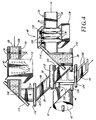
- the differently colored images produced by the printing units 22A, 22B, 22C and 22D are thus transferred onto the surface 28 of the belt 26 in superimposed relation to provide a polychromic image 108 (shown in Fig. 4).
- the polychromic images 108 are then conveyed by the belt 26 to the moistening device 40 which comprises a plurality of spray nozzles 110 arranged in a housing 112.
- An aqueous solution containing a surfactant is sprayed by the nozzles 110 onto the surface 28 of the belt 26 in order to moisten any dried dots of colored, coagulated colloid representative of the images 108, thereby ensuring that the polychromic images 108 are substantially completely transferred from the surface 28 onto the paper web 44 by the transfer device 42.
- the transfer device 42 comprises a pair of inclined turn bars 114, 114' and a pair of guide rollers 116, 116' disposed relative to one another for guiding the belt 26 so that it travels along a horizontal path with the surface 28 facing downwardly, thereby exposing the surface 28 to permit contacting thereof by the paper web 44.
- the device further includes a support roller 118 and a pressure roller 120 extending parallel to the roller 118 and pressed thereagainst to form a nip 122 through which the belt 26 is passed and to permit the rollers 118, 120 to be driven by the belt 26 upon movement thereof.
- the rotation axes of the support roller 118 and pressure roller 120 are disposed in a plane which extends perpendicular to the horizontal path along which the belt 26 travels.
- the paper web 44 is guided by a pair of guide rollers 124, 124' so as to pass through the nip 122 between the pressure roller 120 and the surface 28 of the belt 26, for being imprinted with the polychromic images 108 which are transferred from the surface 28 onto the web 44.
- the paper web 44 imprinted with the images 108 is then taken up by a collect roller 126.
- the cleaning device 48 comprises two rotating brushes 128, three high pressure water injectors 130 (shown in Fig. 1) and a rubber squeegee 132 disposed on one side of the belt 26, as well as three support rollers 134 disposed on the other side of the belt, all being arranged in a housing 136.
- Each brush 128 rotates in a clockwise manner and is provided with a plurality of radially extending bristles 74 which are made of horsehair and have extremities contacting the surface 28 of the belt 26. Any coagulated colloid remaining on the surface 28 is thus removed by the brushes 128 and washed away by the powerful jets of water produced by the injectors 130.
Landscapes
- Chemical & Material Sciences (AREA)
- Dispersion Chemistry (AREA)
- Engineering & Computer Science (AREA)
- Manufacturing & Machinery (AREA)
- Printing Methods (AREA)
- Duplication Or Marking (AREA)
- Color, Gradation (AREA)
Applications Claiming Priority (2)
| Application Number | Priority Date | Filing Date | Title |
|---|---|---|---|
| CA2214300 | 1997-08-29 | ||
| CA 2214300 CA2214300C (fr) | 1997-08-29 | 1997-08-29 | Methode et appareil d'impression polychrome par electrocoagulation |
Publications (3)
| Publication Number | Publication Date |
|---|---|
| EP0899094A2 true EP0899094A2 (fr) | 1999-03-03 |
| EP0899094A3 EP0899094A3 (fr) | 1999-05-06 |
| EP0899094B1 EP0899094B1 (fr) | 2001-07-25 |
Family
ID=4161370
Family Applications (1)
| Application Number | Title | Priority Date | Filing Date |
|---|---|---|---|
| EP19980116247 Expired - Lifetime EP0899094B1 (fr) | 1997-08-29 | 1998-08-27 | Procédé et appareil d'impression par électrocoagulation multicolore |
Country Status (4)
| Country | Link |
|---|---|
| EP (1) | EP0899094B1 (fr) |
| JP (1) | JPH11129550A (fr) |
| CA (1) | CA2214300C (fr) |
| DE (1) | DE69801194T2 (fr) |
Cited By (2)
| Publication number | Priority date | Publication date | Assignee | Title |
|---|---|---|---|---|
| EP0909799A1 (fr) * | 1997-03-17 | 1999-04-21 | Toyo Ink Manufacturing Co. Ltd. | Encre d'impression par electrocoagulation |
| EP1084829A2 (fr) * | 1999-09-15 | 2001-03-21 | Toyo Ink Mfg. Co., Ltd. | Méthode d'impression par électrocoagulation et dispositif pour la production d'images avec une résolution améliorée |
Families Citing this family (2)
| Publication number | Priority date | Publication date | Assignee | Title |
|---|---|---|---|---|
| CA2282128C (fr) * | 1999-09-14 | 2004-03-02 | Adrien Castegnier | Anode d'acier inoxydable pour impression par electrocoagulation |
| CA2282188C (fr) * | 1999-09-15 | 2005-04-26 | Adrien Castegnier | Methode et appareil d'impression par electrocoagulation intermittente |
Citations (3)
| Publication number | Priority date | Publication date | Assignee | Title |
|---|---|---|---|---|
| FR424094A (fr) * | 1910-07-08 | 1911-05-04 | John Arthur Jefferson Hayes | Perfectionnements aux presses à imprimer |
| US4661222A (en) * | 1986-03-27 | 1987-04-28 | Elcorsy Inc. | Monochromic and polychromic printing of an image reproduced by electro-coagulation of a colloid |
| US5538601A (en) * | 1995-09-14 | 1996-07-23 | Elcorsy Inc. | Electrocoagulation printing and apparatus |
-
1997
- 1997-08-29 CA CA 2214300 patent/CA2214300C/fr not_active Expired - Fee Related
-
1998
- 1998-08-17 JP JP10230729A patent/JPH11129550A/ja active Pending
- 1998-08-27 EP EP19980116247 patent/EP0899094B1/fr not_active Expired - Lifetime
- 1998-08-27 DE DE1998601194 patent/DE69801194T2/de not_active Expired - Fee Related
Patent Citations (3)
| Publication number | Priority date | Publication date | Assignee | Title |
|---|---|---|---|---|
| FR424094A (fr) * | 1910-07-08 | 1911-05-04 | John Arthur Jefferson Hayes | Perfectionnements aux presses à imprimer |
| US4661222A (en) * | 1986-03-27 | 1987-04-28 | Elcorsy Inc. | Monochromic and polychromic printing of an image reproduced by electro-coagulation of a colloid |
| US5538601A (en) * | 1995-09-14 | 1996-07-23 | Elcorsy Inc. | Electrocoagulation printing and apparatus |
Cited By (4)
| Publication number | Priority date | Publication date | Assignee | Title |
|---|---|---|---|---|
| EP0909799A1 (fr) * | 1997-03-17 | 1999-04-21 | Toyo Ink Manufacturing Co. Ltd. | Encre d'impression par electrocoagulation |
| EP0909799B1 (fr) * | 1997-03-17 | 2003-06-25 | Toyo Ink Manufacturing Co. Ltd. | Encre d'impression par electrocoagulation |
| EP1084829A2 (fr) * | 1999-09-15 | 2001-03-21 | Toyo Ink Mfg. Co., Ltd. | Méthode d'impression par électrocoagulation et dispositif pour la production d'images avec une résolution améliorée |
| EP1084829A3 (fr) * | 1999-09-15 | 2002-04-17 | Toyo Ink Mfg. Co., Ltd. | Méthode d'impression par électrocoagulation et dispositif pour la production d'images avec une résolution améliorée |
Also Published As
| Publication number | Publication date |
|---|---|
| JPH11129550A (ja) | 1999-05-18 |
| CA2214300C (fr) | 2002-11-19 |
| CA2214300A1 (fr) | 1999-02-28 |
| EP0899094B1 (fr) | 2001-07-25 |
| DE69801194T2 (de) | 2002-03-14 |
| DE69801194D1 (de) | 2001-08-30 |
| EP0899094A3 (fr) | 1999-05-06 |
Similar Documents
| Publication | Publication Date | Title |
|---|---|---|
| US5727462A (en) | Multicolor dynamic printing method and apparatus | |
| WO1990011897A1 (fr) | Procede et appareil d'impression par electrocoagulation a haute vitesse | |
| US5908541A (en) | Multicolor electrocoagulation printing method and apparatus | |
| EP0899094B1 (fr) | Procédé et appareil d'impression par électrocoagulation multicolore | |
| US6045674A (en) | Intermittent electrocoagulation printing method and apparatus | |
| EP1084829B1 (fr) | Méthode d'impression par électrocoagulation et dispositif pour la production d'images avec une résolution améliorée | |
| CA2214606C (fr) | Methode permettant d'empecher l'abrasion de l'electrode positive en cours d'impression par electrocoagulation | |
| US5690803A (en) | Method of enhancing transfer of coagulated colloid onto a substrate during electrocoagulation printing | |
| US5690801A (en) | Method of rendering an electrocoagulation printed image water-fast | |
| US5863402A (en) | Method of preventing anode abrasion during electrocoagulation printing | |
| CA2156978C (fr) | Procede et dispositif d'impression polychrome | |
| CA2282188C (fr) | Methode et appareil d'impression par electrocoagulation intermittente | |
| US6551481B2 (en) | Electrocoagulation printing method and apparatus providing color juxtaposition | |
| CA2334265C (fr) | Methode d'impression par electrocoagulation et appareil assurant une resolution d'image amelioree | |
| US5690802A (en) | Method of increasing coagulation efficiency during electrocoagulation printing | |
| US6458261B2 (en) | Electrocoagulation printing method and apparatus providing enhanced image resolution | |
| CA2194129C (fr) | Methode pour rendre indelebile une image imprimee par electrocoagulation | |
| CA2355458C (fr) | Methode d'impression par electrocoagulation et appareil assurant la juxtaposition des couleurs | |
| CA2194130C (fr) | Methode pour ameliorer le transfert d'un colloide coagule sur un substrat dans l'impression par electrocoagulation | |
| US6755950B2 (en) | Electrocoagulation printing method providing an image having enhanced optical density | |
| EP1285748A2 (fr) | Procédé d'impression par électrocoagulation et appareil permettant la juxtaposition de couleurs | |
| EP0931666B1 (fr) | Procede et appareil d'impression par coagulation electrique | |
| CA2194128C (fr) | Methode pour accroitre le rendement de coagulation dans l'impression par electrocoagulation | |
| EP0822462A1 (fr) | Procede et dispositif d'impression par coagulation electrique | |
| EP1084827A2 (fr) | Electrode positive pour l'impression par coagulation |
Legal Events
| Date | Code | Title | Description |
|---|---|---|---|
| PUAI | Public reference made under article 153(3) epc to a published international application that has entered the european phase |
Free format text: ORIGINAL CODE: 0009012 |
|
| AK | Designated contracting states |
Kind code of ref document: A2 Designated state(s): DE FR GB |
|
| AX | Request for extension of the european patent |
Free format text: AL;LT;LV;MK;RO;SI |
|
| PUAL | Search report despatched |
Free format text: ORIGINAL CODE: 0009013 |
|
| AK | Designated contracting states |
Kind code of ref document: A3 Designated state(s): AT BE CH CY DE DK ES FI FR GB GR IE IT LI LU MC NL PT SE |
|
| AX | Request for extension of the european patent |
Free format text: AL;LT;LV;MK;RO;SI |
|
| 17P | Request for examination filed |
Effective date: 19991027 |
|
| AKX | Designation fees paid |
Free format text: DE FR GB |
|
| GRAG | Despatch of communication of intention to grant |
Free format text: ORIGINAL CODE: EPIDOS AGRA |
|
| 17Q | First examination report despatched |
Effective date: 20000816 |
|
| GRAG | Despatch of communication of intention to grant |
Free format text: ORIGINAL CODE: EPIDOS AGRA |
|
| GRAH | Despatch of communication of intention to grant a patent |
Free format text: ORIGINAL CODE: EPIDOS IGRA |
|
| GRAH | Despatch of communication of intention to grant a patent |
Free format text: ORIGINAL CODE: EPIDOS IGRA |
|
| GRAA | (expected) grant |
Free format text: ORIGINAL CODE: 0009210 |
|
| AK | Designated contracting states |
Kind code of ref document: B1 Designated state(s): DE FR GB |
|
| REF | Corresponds to: |
Ref document number: 69801194 Country of ref document: DE Date of ref document: 20010830 |
|
| ET | Fr: translation filed | ||
| REG | Reference to a national code |
Ref country code: GB Ref legal event code: IF02 |
|
| PLBE | No opposition filed within time limit |
Free format text: ORIGINAL CODE: 0009261 |
|
| STAA | Information on the status of an ep patent application or granted ep patent |
Free format text: STATUS: NO OPPOSITION FILED WITHIN TIME LIMIT |
|
| 26N | No opposition filed | ||
| PGFP | Annual fee paid to national office [announced via postgrant information from national office to epo] |
Ref country code: FR Payment date: 20030808 Year of fee payment: 6 |
|
| PGFP | Annual fee paid to national office [announced via postgrant information from national office to epo] |
Ref country code: GB Payment date: 20030827 Year of fee payment: 6 |
|
| PGFP | Annual fee paid to national office [announced via postgrant information from national office to epo] |
Ref country code: DE Payment date: 20030904 Year of fee payment: 6 |
|
| PG25 | Lapsed in a contracting state [announced via postgrant information from national office to epo] |
Ref country code: GB Free format text: LAPSE BECAUSE OF NON-PAYMENT OF DUE FEES Effective date: 20040827 |
|
| PG25 | Lapsed in a contracting state [announced via postgrant information from national office to epo] |
Ref country code: DE Free format text: LAPSE BECAUSE OF NON-PAYMENT OF DUE FEES Effective date: 20050301 |
|
| GBPC | Gb: european patent ceased through non-payment of renewal fee |
Effective date: 20040827 |
|
| PG25 | Lapsed in a contracting state [announced via postgrant information from national office to epo] |
Ref country code: FR Free format text: LAPSE BECAUSE OF NON-PAYMENT OF DUE FEES Effective date: 20050429 |
|
| REG | Reference to a national code |
Ref country code: FR Ref legal event code: ST |