EP0899080A2 - Method and apparatus for manufacturing a tyre bead filler - Google Patents
Method and apparatus for manufacturing a tyre bead filler Download PDFInfo
- Publication number
- EP0899080A2 EP0899080A2 EP98306876A EP98306876A EP0899080A2 EP 0899080 A2 EP0899080 A2 EP 0899080A2 EP 98306876 A EP98306876 A EP 98306876A EP 98306876 A EP98306876 A EP 98306876A EP 0899080 A2 EP0899080 A2 EP 0899080A2
- Authority
- EP
- European Patent Office
- Prior art keywords
- filler
- roller
- forming
- shape
- contact surface
- Prior art date
- Legal status (The legal status is an assumption and is not a legal conclusion. Google has not performed a legal analysis and makes no representation as to the accuracy of the status listed.)
- Granted
Links
Images


Classifications
-
- B—PERFORMING OPERATIONS; TRANSPORTING
- B29—WORKING OF PLASTICS; WORKING OF SUBSTANCES IN A PLASTIC STATE IN GENERAL
- B29D—PRODUCING PARTICULAR ARTICLES FROM PLASTICS OR FROM SUBSTANCES IN A PLASTIC STATE
- B29D30/00—Producing pneumatic or solid tyres or parts thereof
- B29D30/06—Pneumatic tyres or parts thereof (e.g. produced by casting, moulding, compression moulding, injection moulding, centrifugal casting)
- B29D30/48—Bead-rings or bead-cores; Treatment thereof prior to building the tyre
-
- B—PERFORMING OPERATIONS; TRANSPORTING
- B29—WORKING OF PLASTICS; WORKING OF SUBSTANCES IN A PLASTIC STATE IN GENERAL
- B29C—SHAPING OR JOINING OF PLASTICS; SHAPING OF MATERIAL IN A PLASTIC STATE, NOT OTHERWISE PROVIDED FOR; AFTER-TREATMENT OF THE SHAPED PRODUCTS, e.g. REPAIRING
- B29C48/00—Extrusion moulding, i.e. expressing the moulding material through a die or nozzle which imparts the desired form; Apparatus therefor
- B29C48/03—Extrusion moulding, i.e. expressing the moulding material through a die or nozzle which imparts the desired form; Apparatus therefor characterised by the shape of the extruded material at extrusion
- B29C48/07—Flat, e.g. panels
-
- B—PERFORMING OPERATIONS; TRANSPORTING
- B29—WORKING OF PLASTICS; WORKING OF SUBSTANCES IN A PLASTIC STATE IN GENERAL
- B29C—SHAPING OR JOINING OF PLASTICS; SHAPING OF MATERIAL IN A PLASTIC STATE, NOT OTHERWISE PROVIDED FOR; AFTER-TREATMENT OF THE SHAPED PRODUCTS, e.g. REPAIRING
- B29C48/00—Extrusion moulding, i.e. expressing the moulding material through a die or nozzle which imparts the desired form; Apparatus therefor
- B29C48/03—Extrusion moulding, i.e. expressing the moulding material through a die or nozzle which imparts the desired form; Apparatus therefor characterised by the shape of the extruded material at extrusion
- B29C48/12—Articles with an irregular circumference when viewed in cross-section, e.g. window profiles
-
- B—PERFORMING OPERATIONS; TRANSPORTING
- B29—WORKING OF PLASTICS; WORKING OF SUBSTANCES IN A PLASTIC STATE IN GENERAL
- B29C—SHAPING OR JOINING OF PLASTICS; SHAPING OF MATERIAL IN A PLASTIC STATE, NOT OTHERWISE PROVIDED FOR; AFTER-TREATMENT OF THE SHAPED PRODUCTS, e.g. REPAIRING
- B29C48/00—Extrusion moulding, i.e. expressing the moulding material through a die or nozzle which imparts the desired form; Apparatus therefor
- B29C48/25—Component parts, details or accessories; Auxiliary operations
- B29C48/30—Extrusion nozzles or dies
- B29C48/35—Extrusion nozzles or dies with rollers
-
- B—PERFORMING OPERATIONS; TRANSPORTING
- B60—VEHICLES IN GENERAL
- B60C—VEHICLE TYRES; TYRE INFLATION; TYRE CHANGING; CONNECTING VALVES TO INFLATABLE ELASTIC BODIES IN GENERAL; DEVICES OR ARRANGEMENTS RELATED TO TYRES
- B60C15/00—Tyre beads, e.g. ply turn-up or overlap
- B60C15/06—Flipper strips, fillers, or chafing strips and reinforcing layers for the construction of the bead
-
- B—PERFORMING OPERATIONS; TRANSPORTING
- B29—WORKING OF PLASTICS; WORKING OF SUBSTANCES IN A PLASTIC STATE IN GENERAL
- B29C—SHAPING OR JOINING OF PLASTICS; SHAPING OF MATERIAL IN A PLASTIC STATE, NOT OTHERWISE PROVIDED FOR; AFTER-TREATMENT OF THE SHAPED PRODUCTS, e.g. REPAIRING
- B29C43/00—Compression moulding, i.e. applying external pressure to flow the moulding material; Apparatus therefor
- B29C43/32—Component parts, details or accessories; Auxiliary operations
- B29C43/44—Compression means for making articles of indefinite length
- B29C43/46—Rollers
- B29C2043/466—Rollers the rollers having specific shape, e.g. non cylindrical rollers, conical rollers
-
- B—PERFORMING OPERATIONS; TRANSPORTING
- B29—WORKING OF PLASTICS; WORKING OF SUBSTANCES IN A PLASTIC STATE IN GENERAL
- B29C—SHAPING OR JOINING OF PLASTICS; SHAPING OF MATERIAL IN A PLASTIC STATE, NOT OTHERWISE PROVIDED FOR; AFTER-TREATMENT OF THE SHAPED PRODUCTS, e.g. REPAIRING
- B29C43/00—Compression moulding, i.e. applying external pressure to flow the moulding material; Apparatus therefor
- B29C43/32—Component parts, details or accessories; Auxiliary operations
- B29C43/44—Compression means for making articles of indefinite length
- B29C43/46—Rollers
-
- B—PERFORMING OPERATIONS; TRANSPORTING
- B29—WORKING OF PLASTICS; WORKING OF SUBSTANCES IN A PLASTIC STATE IN GENERAL
- B29C—SHAPING OR JOINING OF PLASTICS; SHAPING OF MATERIAL IN A PLASTIC STATE, NOT OTHERWISE PROVIDED FOR; AFTER-TREATMENT OF THE SHAPED PRODUCTS, e.g. REPAIRING
- B29C48/00—Extrusion moulding, i.e. expressing the moulding material through a die or nozzle which imparts the desired form; Apparatus therefor
- B29C48/03—Extrusion moulding, i.e. expressing the moulding material through a die or nozzle which imparts the desired form; Apparatus therefor characterised by the shape of the extruded material at extrusion
- B29C48/07—Flat, e.g. panels
- B29C48/08—Flat, e.g. panels flexible, e.g. films
-
- B—PERFORMING OPERATIONS; TRANSPORTING
- B29—WORKING OF PLASTICS; WORKING OF SUBSTANCES IN A PLASTIC STATE IN GENERAL
- B29D—PRODUCING PARTICULAR ARTICLES FROM PLASTICS OR FROM SUBSTANCES IN A PLASTIC STATE
- B29D30/00—Producing pneumatic or solid tyres or parts thereof
- B29D30/06—Pneumatic tyres or parts thereof (e.g. produced by casting, moulding, compression moulding, injection moulding, centrifugal casting)
- B29D30/48—Bead-rings or bead-cores; Treatment thereof prior to building the tyre
- B29D2030/481—Fillers or apexes
-
- B—PERFORMING OPERATIONS; TRANSPORTING
- B29—WORKING OF PLASTICS; WORKING OF SUBSTANCES IN A PLASTIC STATE IN GENERAL
- B29D—PRODUCING PARTICULAR ARTICLES FROM PLASTICS OR FROM SUBSTANCES IN A PLASTIC STATE
- B29D30/00—Producing pneumatic or solid tyres or parts thereof
- B29D30/06—Pneumatic tyres or parts thereof (e.g. produced by casting, moulding, compression moulding, injection moulding, centrifugal casting)
- B29D30/48—Bead-rings or bead-cores; Treatment thereof prior to building the tyre
- B29D2030/482—Applying fillers or apexes to bead cores
-
- Y—GENERAL TAGGING OF NEW TECHNOLOGICAL DEVELOPMENTS; GENERAL TAGGING OF CROSS-SECTIONAL TECHNOLOGIES SPANNING OVER SEVERAL SECTIONS OF THE IPC; TECHNICAL SUBJECTS COVERED BY FORMER USPC CROSS-REFERENCE ART COLLECTIONS [XRACs] AND DIGESTS
- Y10—TECHNICAL SUBJECTS COVERED BY FORMER USPC
- Y10T—TECHNICAL SUBJECTS COVERED BY FORMER US CLASSIFICATION
- Y10T156/00—Adhesive bonding and miscellaneous chemical manufacture
- Y10T156/10—Methods of surface bonding and/or assembly therefor
- Y10T156/1002—Methods of surface bonding and/or assembly therefor with permanent bending or reshaping or surface deformation of self sustaining lamina
- Y10T156/1007—Running or continuous length work
- Y10T156/1008—Longitudinal bending
- Y10T156/101—Prior to or during assembly with additional lamina
Definitions
- the present invention relates to a method of manufacturing a bead filler and an apparatus for forming a filler portion, and more particularly to a method of manufacturing a bead filler constituted by a core portion and a filler portion and disposed in a curved side portion of a pneumatic tire and a filler portion forming apparatus for forming the filler portion.
- a bead filler composed of a bead core and a filler portion is disposed.
- the bead core of the bead filler is formed in a circular ring shape by twisting a plurality of cords into one.
- the filler portion is made from a rubber composition having a predetermined length, and is formed by linearly extruding the rubber composition in a substantially triangular cross sectional shape having a thick base portion and a thin top poriton.
- the filler portion having a substantially triangular cross sectional shape is disposed in such a manner that one side of the triangle is brought into contact with the carcass ply main body portion 12A, one side is brought into contact with a bead core 22 and one side is brought into contact with a carcass ply turned-up portion 12B, as shown in Fig. 2.
- a filler portion 82 extruded to a predetermined length is wound around a periphery of a bead core 84 having a circular ring shape.
- the filler portion 82 is in a linearly extruded belt shape, it is wound substantially in a perpendicular state along an axial direction of the ring-like bead core 84 such that a top portion of the filler portion 82 is disposed in a perpendicular state to a radical direction of the bead core 84.
- the winding start end When the winding start end is first mounted to the bead core 84 and the filler portion 82 is wound around once in a manner that a base portion of the filler portion 82 is disposed to contact with a peripheral portion of the bead core 84, the winding finish end overlaps and presses onto the winding start end. Accordingly, the winding start end and the winding finish end are joined, and a bead filler 80 integrally constructed by the filler portion 82 and the bead core 84 is formed.
- the filler portion 82 is pulled by the top portion thereof in the direction shown by the arrow M and is formed in a shape similar to the shape of the side portion of the pneumatic tire.
- the bead filler 80 formed in the shape similar to the shape of the side portion of the pneumatic tire, is mounted on the carcass ply placed on a forming drum and disposed in the side portion of the pneumatic tire by turning up the turned-up portion 12B of the carcass ply around the bead filler 80.
- the rubber composition is stretched out at the top portion of the filler portion 82 so that the diametrical size is greatly increased.
- the base portion of the filler portion 82 is joined to the bead core 84, the diametrical size of the base portion of the filler portion 82 is only slightly changed. Accordingly, a great difference in diameter is generated between the base portion and the top portion of the filler portion 82.
- the amount of the opening is anticipated in advance and the rubber composition is excessively overlapped at that portion so that the joined portion does not open up at the top portion of the filler portion 82. Accordingly, even if the joined portion is stretched when the diametrical size has increased greatly by pulling up the filler portion 82, the winding start end and the winding finish end of the filler portion 82 are not separated from each other, so that a bead filler 80 formed in a shape similar to the shape of the side portion of the pneumatic tire can be obtained.
- the overlapped amount becomes great. Accordingly, there are cases where a great difference in thickness is generated between the overlapped portion and the portion not overlapped. Further, the front end of the bead filler 80 is stretched by the anticipated amount so as to be the original thickness, however, the base portion which is overlapped by the same amount as the top portion is less stretched than the top portion. Accordingly, there are cases where the thickness of the filler portion 82 is uneven in the overlapped portion. As mentioned above, when unevenness is generated in the filler portion 82 along the circumferential direction of the side portion of the pneumatic tire, the unevenness becomes an unevenness along the circumferential direction of the side portion of the pneumatic tire, so that the uniformity of the pneumatic tire is deteriorated.
- the present invention was made by taking the facts mentioned above into consideration, and an object of the present invention is to provide a method of manufacturing a bead filler which can easily manufacture a bead filler not deteriorating the uniformity of a pneumatic tire, and a filler portion forming apparatus which can form the filler portion of this kind.
- a method of manufacturing a bead filler comprising an annular core portion and a filler portion formed by extruding a rubber composition in a specific cross sectional shape and disposed in a curved side portion along the circumferential direction of the side portion of a pneumatic tire, wherein the filler portion is formed by extruding the rubber composition in a curved shape corresponding to the shape of the side portion of the pneumatic tire.
- a bead filler since the filler portion is formed by extruding the rubber composition in a curved shape corresponding to the shape of the side portion of the pneumatic tire, a bead filler can be constructed which is integrally formed with the bead portion and already corresponds to the shape of the side portion of the pneumatic tire. Accordingly, a great change in the shape such as an expansion of the diameter by pulling the top portion of the filler portion is not required after constructing the bead filler, so that the time and labor hitherto required for the pulling process and the various process accompanying this process can be removed.
- the thickness and width of the overlapping portion between the winding start end and the winding finish end of the filler portion can be reduced. Accordingly, unevenness of the thickness of the filler portion along the circumferential direction of the side portion of the pneumatic tire is reduced, and the uniformity of a produced tire not thereby deteriorated. Therefore, a bead filler can be easily manufactured without deteriorating the uniformity of the pneumatic tire.
- the description of the curved shape corresponding to the shape of the side portion of the pneumatic tire indicates all curved shapes intentionally extruded in the shape of the side portion of the pneumatic tire. In other words, not only a curved shape perfectly matching the shape of the side portion of the pneumatic tire, but also a curved shape similar to the shape of the side portion are included in this term.
- the surface velocities of both ends in the widthwise direction of the roller opposing to the forming portion changes on the basis of the diameter. Accordingly, the width and the thickness of the joint portion between the winding start end and the winding finish end of the filler portion joined to the core portion can be optimized. Accordingly, in the case of disposing the obtained filler portion in the side portion of the pneumatic tire, a filler portion having even less unevenness in the peripheral direction can be easily obtained.
- the filler portion is formed by extruding the rubber composition in the curved shape corresponding to the shape of the side portion of the pneumatic tire, the bead filler can be easily obtained without deteriorating the uniformity of the pneumatic tire.
- the rubber composition extruded by the extruding means is fed out in the curved shape corresponding to the shape of the side portion of the pneumatic tire in the extruding direction while being formed in the predetermined cross sectional shape by the roller and the forming portion, it is not necessary to change the shape of the obtained filler portion, so that the bead filler can be easily obtained without deteriorating a uniformity of the produced tire.
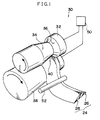
- Fig. 1 is a schematically perspective view of a forming apparatus in accordance with an embodiment of the present invention.
- Fig. 2 is a cross sectional view along an axial line of a tire in accordance with an embodiment of the present invention.
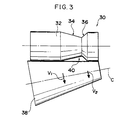
- Fig. 3 is a side elevational view of a forming apparatus in accordance with an embodiment of the present invention.
- Fig. 4A is a plan view of a filler portion formed by a forming apparatus.
- Fig. 4B is a cross sectional view of Fig. 4A.
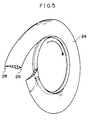
- Fig. 5 is a schematic view showing a state in which a bead filler is constituted by a filler portion obtained by a forming apparatus in accordance with an embodiment of the present invention and a bead core.
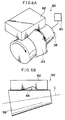
- Fig. 6A is a schematically perspective view of a forming apparatus in accordance with another embodiment of the present invention.
- Fig. 6B is a side elevational view of Fig. 6A.
- Fig. 7A is a schematically side elevational view of a bead filler obtained in a step of a conventional method of forming a bead filler.
- Fig. 7B is a schematically side elevational view of a bead filler obtained in the next step of Fig. 7A.
- a forming apparatus 30 in accordance with an embodiment of the present invention is shown in Fig. 1.
- the forming apparatus 30 forms the filler portion 24 of a bead filler 20 provided in a pneumatic tire 10 (the tire size is 205/65R15, hereinafter, simply referred to as a tire).
- Fig. 2 shows a part of the tire 10 provided with the bead filler 20 including the filler portion 24 formed by the forming apparatus 30.
- a carcass ply 12 formed in a toroidal shape is provided, and the bead filler 20 is disposed between a main body portion 12A and a turned-up portion 12B of the carcass ply 12.
- a belt 14 comprising a plurality of layers is disposed outside the carcass ply 12 in a radial direction, and a tread 16 is disposed outside the belt 14 in the radial direction.
- the bead filler 20 is composed of a bead core 22 composed of a plurality of intertwisted steel cords and a filler portion 24 formed from a single rubber body or a composite rubber material such as a fiber reinforcing rubber and the like.
- the turned-up portion 12B of the carcass ply 12 is wound around the filler portion 24 encircling the bead core 22 turned-up.
- the filler portion 24 of the bead filler 20 is formed in a substantially triangular cross sectional shape, and is composed of a base portion 26 corresponding to the bottom side of the triangle and a top portion 28 corresponding to the vertex of the triangle (refer to Fig. 1).
- the filler portion 24 is joined to the bead core 22 at the base portion 26, and the top portion 28 is disposed facing towards the tread 16 of the tire 10.
- An outer side in the tire axial direction of the carcass ply 12 is formed as the side portion 18, in which a side rubber 19 extending to the bead core 22 of the bead filler 20 from an end portion of the tread 16 is disposed.
- the side rubber 18 covers a surface of the bead filler 20 from the bead core 22 to the end portion of the tread 16.
- the side portion 18 of the tire 10 is maintained in a curved shape by the carcass ply 12 which is formed in a toroidal shape. Accordingly, the side rubber 18 and the bead filler 20 are curved in accordance with the shape of the carcass ply 12 so as to cover the surface of the carcass ply 12.
- the filler portion 24 is formed in a substantially triangular cross sectional shape comprising a bottom side 25, and sides 27 and 29, as shown in Fig. 4B.
- the filler portion 24 is disposed in such a manner that the bottom side 25 is brought into contact with the bead core 22, the side 27 is brought into contact with the carcass ply turned-up portion 12B and the side 29 is brought into contact with the carcass ply main body 12A, as shown in Fig. 2.
- the filler portion 24 constituting the bead filler 20 of the tire 10 of this kind is formed by a forming apparatus 30 shown in Fig. 1.
- the forming apparatus 30 is composed of an extruding roller 38 for forming the rubber composition constituting the filler portion 24 and extruding the rubber composition in the curved shape of the filler portion 24, and a forming roller 32.
- the forming roller 32 is formed in a cylindrical shape constricted in the central portion thereof.
- the constricted portion of the forming roller 32 is formed by continuously reducing the diameter at different ratios from both ends in the direction of the rotational axis. Accordingly, the diameter of the forming roller 32 is reduced at different ratios, and has two peripheral surfaces 34 and 36 having different lengths in the rotational axis direction.
- the extruding roller 38 is formed in a substantially truncated cone shape longer than the forming roller 32, and the diameter around the rotational axis C continuously changes along the direction of the rotational axis C.
- the size of the smallest diameter around the rotational axis C of the extruding roller 38 is the same as the diametrical size of the forming roller 32.
- the rotational axis C of the extruding roller 38 is disposed at an inclination to the rotational axis of the forming roller 32, and the peripheral surfaces of the extruding roller 38 and the forming roller 32 are adjacent to and facing each other.
- a triangular gap is formed between the extruding roller 38 and the forming roller 32.
- the gap corresponds to a forming portion 40 for forming the rubber composition in a shape of the filler portion 24.
- the cross sectional shape along the rotational axis of the forming roller 32 in the forming portion to is formed in a triangular shape substantially coinciding with the cross sectional shape of the filler portion 24, the peripheral surface of the forming roller 32 forms the bottom side of the filler portion 24 (the portion in contact with the peripheral surface 36, corresponding to reference numeral 25 in Fig. 4B) and one of the long sides (the portion in contact with the peripheral surface 34, corresponding to reference numeral 27 in Fig. 4B) of the filler portion 24, and the peripheral surface of the extruding roller 38 forms the other of the long sides (corresponding to reference numeral 29 in Fig. 4B) of the filler portion 24.
- the diameter contraction ratio and the shape of the diameter contracted portion of the forming roller 32, constituting a part of the forming portion 40 are determined in correspondence to the cross sectional shape of the filler portion 24.
- the forming portion 40 disposes the portion forming the base portion 26 (the side nearest the reference numeral 25 in Fig. 4B) of the filler portion 24 at the end of the extruding roller 38 having the smaller diameter, and disposes the portion forming the top portion 28 (the side nearest the reference numeral 27 end in Fig. 4B) of the filler portion 24 at the end of the extruding roller 38 having the larger diameter.
- the surface velocity V 2 of the extruding roller 38 at the end of the forming portion 40 corresponding to the base portion 26 of the filler portion 24 is set to be lower than the surface velocity V 1 of the extruding roller 38 at the end portion of the forming portion 40 corresponding to the top portion 28 of the filler portion 24 in accordance with the diameter of the extruding roller 38.
- the ratio V 1 : V 2 of the surface velocities is set to be from 1.0 : 3.0 to 1.0 : 10.0. Inside this range, the shape of the obtained filler portion 24 becomes dissimilar to the shape of the side portion 18 of the tire 10, resulting in there being no need to greatly change the shape after forming, or causing the width and thickness of the overlapped portion to be even, and is thus preferable.
- the ratio of the surface velocities is set to be from 1.0 : 5.0 to 1.0 : 7.0. In this case, the ratio of the velocities corresponds to the diameter of the extruding roller 38 in the forming portion 40.
- a feeding-out portion (not shown) is disposed upstream at the forming roller 32 and the extruding roller 38 in Fig. 1.
- the feeding-out portion feeds out the rubber composition forming the filler portion 24 toward the forming roller 32 and the extruding roller 38.
- the rotational axis C of the extruding roller 38 is connected to a drive portion 50 with the motor at the side at which the diametrical size is smaller. Further the drive portion 50 is connected to the rotational axis of the forming roller 32. The extruding roller 38 and the forming roller 32 are rotated at the same rotating speed per unit time by the same motor.
- a guiding roller 52 is disposed below the extruding roller 38.
- the guiding roller 52 guides the filler portion 24 formed and extruded from the extruding roller 38 to the downstream side the extruding roller 38.
- a joining apparatus (not shown) for joining the filler portion 24 to the bead core 22 is disposed downstream from the forming apparatus for the filler portion 24.
- Rotating means such as a drum for fitting and rotating the bead core 22 is provided in the joining apparatus.
- the drum has a diameter capable of winding the bead core 22 therearound, and is connected to a motor for rotating the drum (in a single direction).
- a joining apparatus for joining the filler portion 24 to the bead core 22 and an adhering apparatus for joining the winding finish end to the winding start end of the filler portion 24 are disposed at a position on the periphery of the bead core 22 wound around the drum.
- the adhering apparatus performs an adhesion by heating the filler portion 24.
- the forming apparatus 30 forms the forming portion 40 in the shape of the filler portion 24 by means of the extruding roller 38 having a truncated cone shape.
- the rubber composition disposed at the end portion of the top portion 28 is extruded at a surface velocity V 1
- the rubber composition disposed at the end portion of the base portion 26 is extruded at a surface velocity V 2 .
- the filler portion 24 having a curved shape similar to the shape of the side portion 18 of the tire 10 is formed due to the difference in speed between the surface velocity V 1 and the surface velocity V 2 .
- the filler portion 24 is successively joined to the annular bead core 22 from the winding start end so as to be wound around the bead core 22, and is disposed in the side portion 18 of the tire 10 in the tire-forming step after the end portions of the filler portion 24 are adhered and joined together thus forming the bead filler 20.
- the extruding roller 38 is rotated by the driving action of the drive portion 50.
- the forming roller 32 disposed in such a manner as to be in contact with the peripheral surface of the extruding roller 38 also rotates.
- the rubber composition While the extruding roller 38 and the forming roller 32 are rotating, when the rubber composition is fed out from the feeding-out portion toward the forming portion 40 disposed between the extruding roller 38 and the forming roller 32, the rubber composition is formed in a triangular cross sectional shape by the peripheral surfaces of the extruding roller 38 and the forming roller 32 in the forming portion 40 (refer to Fig. 4B).
- the rubber composition formed in the forming portion 40 is extruded from the extruding roller 38 by the rotation of the extruding roller 38.
- the diameter around the rotational axis C continuously changes along the C axis direction in the forming portion 40.
- the surface velocity continuously changes along the C axis direction together with the change of the diametrical size, and the speed at which the rubber composition is extruded is set so that the surface velocity V 1 at the end close to the top portion 28 is faster than the surface velocity V 2 of the end close to the base portion 26.
- the amount of rubber composition extruded from both ends of the forming portion 40 per unit time is different, and thus a larger amount of the rubber composition is extruded at the end close to the top portion 28 as this end has the faster surface velocity.
- the rubber composition disposed between the forming roller 32 having the same surface velocity in the axial direction and the extruding roller 38 having varying surface velocities in the axial direction, as it is extruded becomes more distorted the closer to the top portion 28 due to the difference in the surface velocities between the forming roller 32 and the extruding roller 38. Accordingly, as shown in Fig.
- the filler portion 24 is curved and extruded in a circular arc shape with the base portion 26 side which is extruded in a lesser amount forming the inner side. Accordingly, the extruded filler portion 24 is formed in the shape of a sector having the center portion in the radial direction thereof cut out therefrom. The outer peripheral portion formed in this shape corresponds to the top portion 28 side, and the inner peripheral portion corresponds to the base portion 26 side.
- the term "a curved filler portion” or "a substantially circular arc filler portion” herein may correspond to a filler portion formed in a shape mentioned above.
- the obtained filler portion 24 is next cut in a predetermined length set in accordance with the peripheral size of the tire 10, and is joined to the periphery of the bead core 22 previously formed in an annular shape.
- the winding start end of the filler portion 24 cut in a predetermined length is joined to a predetermined position of the annular bead core 22.
- the annular bead core 22 rotates in the direction of the arrow in Fig. 5, so that the filler portion 24 is successively joined to the bead core 22.
- the formed bead filler 20 is formed in a shape similar to the disc formed by the bead core 22 disposed in the inner portion of the bead filler 20 as it is wound around the annular bead core 22.
- the winding finish end of the filler portion 24 reaches the position where the winding start end of the filler portion 24 is mounted.
- the winding finish end of the filler portion 24 is overlapped, adhered and joined to the winding start end of the filler portion 24.
- the filler portion 24 is previously formed in a curved shape similar to the shape of the side portion 18 of the tire 10, there is practically no necessity to modify the shape of the filler portion 24 once the bead filler 20 has been constructed by winding the filler portion 24 around the bead core 22 once and then joining.
- the overlapping portion between the winding start end and the winding finish end of the filler portion 24 is formed in such a manner as to have a substantially the same width from the top portion 28 to the base portion 26 of the filler portion 24.
- the thickness of the overlapping portion of the filler portion 24 can be set to be about 100 to 120 % of the portion not overlapped by the adhesion. Particularly, it can be even thinner in the top portion 28. As a result, the precision of the joint between the winding start end and the winding finish end of the filler portion 24 can be improved. Further, a so-called butt joint, which is joined without overlapping the winding start end and the winding finish end can be achieved.
- the bead filler 20 obtained in this manner has little unevenness in the peripheral direction of the tire and has a radius of curvature of 190 to 400 mm at the center portion in the widthwise direction (the center line E in Fig. 4A), and preferably has a radius of curvature of 220 to 320 mm.
- the tire 10 using this type of the bead filler 20 unevenness in the side portion 18 can be reduced, and the uniformity of the tire 10 can be improved.
- the radius of curvature is inside the range, the thickness in the overlapping portion becomes uniform when the winding start end and the winding finish end are joined, and the evenness decreases, so that the joining precision is improved and is thus preferable.
- the uniformity of the tire 10 is not deteriorated when it is disposed in the side portion 18 of the tire 10. Further, it is not necessary to change the shape after joining the filler portion 24 to the bead core 22, making the rewinding and modifying of the filler portion 24 unnecessary, so that forming efficiency can be improved. Particularly, if the shape of the filler portion 24 completely coincides with the shape of the side portion 18 of the tire 10, the necessity of changing the shape can be completely removed. Accordingly, the bead filler 20 which does not deteriorate the uniformity of the tire 10 can be manufactured with good productivity.
- the bead filler 20 having the filler portion 24 structured so that the thickness of the front end is particularly thin and the extrusion width is as wide as 65 mm or more, can be easily obtained.
- the thickness of the wide filler portion 24 is about 1.5 to 2 mm at the front end. Since the bead filler 20 provided with the wide filler portion 24 of this kind can be disposed with the top portion 28 close to the tread portion 16 at a time of being disposed in the side portion 18 of the tire 10, differences in the rigidity of the side portion 18 can be reduced.
- the bead filler 20 can be manufactured by the same manner as the normal bead filler.
- the forming roller 32 and the extruding roller 38 are disposed adjacent to and facing each other. When they both rotate the rubber composition is extruded thereby forming the filler portion 24. In some cases, the rubber composition is extruded along the face of the extruding roller 38 outside the gap of the forming portion 40. If this happens, the filler portion 24 can be trimmed to the desired shape by a cutting means such as a cutter of laser or the like placed in the downstream direction from the extruding roller 38.
- an extrusion of the filler portion 24 is performed by using the forming roller 32 rotating by the same amount as the extruding roller 38, however, the forming of the filler portion 24 is not limited to being performed by the rotatable forming roller 32.
- Fig. 6 shows a forming apparatus 60 which is another forming apparatus.
- the forming apparatus 60 is structured in the same manner as that of the forming apparatus 10 except that a die 62 is provided in place of the forming roller 32 (in Fig. 6, the guiding roller 52 is omitted from the illustration).
- the forming apparatus 60 is provided with the die 62 above the extruding roller 38 having the same structure as that mentioned above.
- the die 62 is adjacent to and facing the peripheral surface of the extruding roller 38.
- the die 62 is a rectangular member and is provided with a forming portion 64 notched in a shape coinciding with the cross sectional shape of the filler portion 24 (refer to Fig. 6B).
- the rubber composition when the rubber composition is fed out toward the forming portion 64 of the die 62 from the feeding-out portion, the rubber composition is formed in the shape of the filler portion 24 in the forming portion 64 of the die 62.
- the surface velocity of the extruding roller 38 continuously changes along the C axis direction between both end portions of the forming portion 64 in accordance with the diametrical size, in the same manner as mentioned above. Accordingly, the rubber composition is extruded in a shape defined by the die 62 and at a surface velocity in accordance with the diametrical size of the extruding roller 38.
- a filler portion 24 formed in a triangular cross sectional shape and curved in a substantially circular arc shape having the base portion 26 side as a center side in accordance with a surface velocity of the extruding roller 38 can be obtained.
- the obtained filler portion 24 is already similar to the shape of the side portion 18 when the filler portion 24 is disposed in the side portion 18 of the tire 10, it is not necessary to greatly change the shape and the unevenness is not generated in the side portion 18. As a result, a bead filler 20 can be easily obtained without deteriorating the uniformity of the tire 10.
- the shape of the forming portion 64 is made a triangular shape formed by the peripheral surfaces 34 and 36 of the forming roller 32, the notch of the forming portion 64 and the peripheral surface of the extruding roller 38, however, the shape of the peripheral surfaces 34 and 36 of the forming roller 32 and the notch of the forming portion 64 can be optionally changed in accordance with the shape of the filler portion 24 of the desired bead filler 20.
- the rubber composition is extruded in a curved shape and a filler portion 24 formed in a shape matching the side portion 18 is obtained, however, the curved filler portion 24 can be obtained by other means.
- a disc-like rotating plate with its center disposed in the base portion 26 side of the filler portion 24 may be used.
- the rubber composition corresponding to the base portion 26 side of the filler portion 24 and the rubber composition corresponding to the front end portion 28 side can be extruded at different extruding speeds, so that the filler portion 24 curved in a circular arc shape can be obtained in the manner mentioned above.
- transfer direction changing means such as a roller, a hook or the like for changing the transfer direction of the extruded filler portion 24 from the rotating direction of the rotating plate to the downstream side of the extruding direction is disposed on the rotating plate, so that the obtained filler portion 24 is not again guided to the extruding roller 38.
Landscapes
- Engineering & Computer Science (AREA)
- Mechanical Engineering (AREA)
- Manufacturing & Machinery (AREA)
- Tyre Moulding (AREA)
- Extrusion Moulding Of Plastics Or The Like (AREA)
- Tires In General (AREA)
Abstract
Description
Claims (13)
- A method of manufacturing a bead filler comprising an annular core portion and a filler portion formed by extruding a rubber composition in a specific cross sectional shape and disposed in a curved side portion of a pneumatic tire,
wherein said filler portion is formed by extruding said rubber composition in a curved shape corresponding to a shape of the side portion of said pneumatic tire. - A method according to claim 1, wherein said filler portion extruded in the curved shape is joined along the periphery of said annular core portion.
- A method according to claim 1 or 2, wherein said extruded filler portion has a radius of curvature of 190 to 400 mm at a center portion in the extrusion width direction.
- A method according to any one of claims 1 to 3, wherein said extruded filler portion has a cross sectional shape which is thick in a portion close to a center of curvature of the curved shape of said filler portion near a portion joined to said core portion and becomes thinner the further from the center of curvature.
- A method according to any one of claims 1 to 4, wherein said filler portion is extruded by using a roller having different surface velocities at both ends in the extrusion width direction of said filler portion.
- A method according to claim 5, wherein both ends of said filler portion are extruded by said roller in the extrusion width direction with the ratio of the surface speeds of both ends of said roller being between 1.0 : 3.0 to 1.0 : 10.0.
- A method according to any one of claims 1 to 6, wherein said filler portion has an extrusion width of at least 65 mm.
- A method according to claim 4, wherein a specific cross sectional shape of the filler portion is formed in a substantially triangular shape, with the sides of said triangle respectively corresponding to a bead core contact surface portion, a carcass body portion contact surface portion and a carcass turned-up portion contact surface portion,a center of curvature side of a curved shape of said filler portion corresponds to the bead core contact surface portion side, anda side furthest from the center of curvature of the curved shape of said filler portion corresponds to an angle formed by the carcass main body portion contact surface portion and the carcass turned-up portion contact surface portion.
- A filler portion forming apparatus for forming a filler portion constituting a bead filler, which is disposed in a curved side portion of a pneumatic tire and attached to an annular core portion, comprising:a forming means having a forming surface corresponding to a cross sectional shape of said filler portion;a roller opposing to the forming surface of said forming means and constituting the forming portion between the roller and said forming surface; anda drive means for rotating said roller,wherein the diameter of the roller at each end in the width direction of the forming portion of the roller is different to the diameter at the opposite end,wherein said rubber composition is continuously fed by a rotation of said roller, andwherein the filler portion is formed such that a cross sectional shape corresponds to a shape of said forming portion, and a shape in an extruding direction thereof becomes a curved shape corresponding to a shape of the side portion of said pneumatic tire.
- An apparatus according to claim 9, wherein the ratio of said diameters of both ends of said roller is set to be from 1.0 : 3.0 to 1.0 : 10.0.
- A filler portion forming apparatus for forming a filler portion formed in a curved shape from a rubber composition, comprising:wherein the forming means has a forming portion having a cross sectional shape corresponding to a cross sectional shape of said filler portion and is disposed such that an opening portion of the forming portion is in contact with the roller surface anda roller formed in a substantially truncated cone shape;a forming means disposed in such a manner as to be substantially in contact with a roller surface of said roller; anda drive means for rotating said roller,said rubber composition is extruded by rotating said roller so as to form a filler portion formed in a curved shape having a portion fed out from a large diameter side of the roller as an outer periphery and a portion fed out from a small diameter side of the roller as an inner periphery.
- An apparatus according to claim 11, wherein said filler portion is brought into contact with a bead core portion, a carcass ply main body portion and a carcass ply turned-up portion,a cross sectional shape in a diametrical direction of said filler portion is formed in a substantially triangular shape, the sides of said triangle respectively corresponding to a bead core contact surface portion, a carcass ply main body portion contact surface portion and a carcass ply turned-up portion contact surface portion,the cross sectional shape of the forming portion is formed in said substantially triangular shape,a side of said substantially triangular shape corresponds to an opening portion of the forming portion and said opening portion corresponds to the carcass ply main body portion contact surface portion,the other two sides of said substantially triangular shape correspond to both ends of a bottom surface of the forming portion, and respectively correspond to the bead core contact surface portion and the carcass ply turned-up portion contact surface portion, andthe substantially truncated cone shaped small diameter side of said roller is disposed in such a manner as to oppose to the bead core contact surface portion of the forming portion and the large diameter side is arranged in such a manner as to oppose to the carcass ply turned-up portion contact surface portion of the forming portion.
- A filler portion forming apparatus according to claim 12, wherein the ratio between the diameter of the roller on the side opposite to the end portion of the bead core contact surface portion and the diameter of the roller on the side opposite to the end portion of the carcass ply turned-up portion contact surface portion is set to be 1.0 : 3.0 to 1.0 : 10.0.
Applications Claiming Priority (3)
| Application Number | Priority Date | Filing Date | Title |
|---|---|---|---|
| JP23477797 | 1997-08-29 | ||
| JP234777/97 | 1997-08-29 | ||
| JP9234777A JPH1170590A (en) | 1997-08-29 | 1997-08-29 | Bead filler manufacturing method and filler part forming apparatus |
Publications (3)
| Publication Number | Publication Date |
|---|---|
| EP0899080A2 true EP0899080A2 (en) | 1999-03-03 |
| EP0899080A3 EP0899080A3 (en) | 1999-08-11 |
| EP0899080B1 EP0899080B1 (en) | 2003-11-12 |
Family
ID=16976217
Family Applications (1)
| Application Number | Title | Priority Date | Filing Date |
|---|---|---|---|
| EP98306876A Expired - Lifetime EP0899080B1 (en) | 1997-08-29 | 1998-08-27 | Method and apparatus for manufacturing a tyre bead filler |
Country Status (5)
| Country | Link |
|---|---|
| US (1) | US6264780B1 (en) |
| EP (1) | EP0899080B1 (en) |
| JP (1) | JPH1170590A (en) |
| DE (1) | DE69819630T2 (en) |
| ES (1) | ES2209069T3 (en) |
Cited By (2)
| Publication number | Priority date | Publication date | Assignee | Title |
|---|---|---|---|---|
| WO2004095938A3 (en) * | 2003-04-30 | 2005-04-21 | Adrian Richard Marshall | Apparatus and method for producing three-dimensional objects |
| WO2014060382A1 (en) * | 2012-10-19 | 2014-04-24 | Voith Patent Gmbh | Device and method for producing structured plastic yarns, plastic yarn and spiral fabric made from plastic yarn |
Families Citing this family (20)
| Publication number | Priority date | Publication date | Assignee | Title |
|---|---|---|---|---|
| US6630045B1 (en) * | 1999-03-25 | 2003-10-07 | The Goodyear Tire & Rubber Company | Combined bead loading and apex application system |
| KR100493659B1 (en) * | 2000-11-23 | 2005-06-03 | 한국타이어 주식회사 | Bead filler edge processing roller member |
| US6895649B2 (en) * | 2001-08-29 | 2005-05-24 | Zuiko Corporation | Article production method |
| JP4589676B2 (en) * | 2004-08-03 | 2010-12-01 | 住友ゴム工業株式会社 | Manufacturing method of rubber member for tire. |
| JP4685504B2 (en) * | 2005-05-09 | 2011-05-18 | 株式会社ブリヂストン | Method for forming hollow disk-shaped rubber member |
| WO2008006083A2 (en) | 2006-07-07 | 2008-01-10 | Surmodics, Inc. | Beaded wound spacer device |
| US7501033B2 (en) * | 2006-09-06 | 2009-03-10 | The Goodyear Tire & Rubber Co | Chipper and apex subassembly as an intermediate article of manufacture |
| US20090202609A1 (en) * | 2008-01-06 | 2009-08-13 | Keough Steven J | Medical device with coating composition |
| KR100881157B1 (en) * | 2008-10-06 | 2009-02-03 | 주식회사 우성기공 | Roller forming extrusion machine for tire manufacturing |
| KR100881160B1 (en) * | 2008-10-06 | 2009-02-03 | 주식회사 우성기공 | Double Roller Molding Extruder for Tire Manufacturing |
| FR2964591B1 (en) * | 2010-09-10 | 2014-02-14 | Michelin Soc Tech | METHOD FOR MANUFACTURING PNEUMATIC BRAKE USING A BANDLET |
| US20150239157A1 (en) * | 2012-07-31 | 2015-08-27 | Michelin Recherche Et Technique S.A. | Automatic StartUp and Continued Operation of Calendering Drives for Elastomeric Mixes |
| WO2014062839A1 (en) | 2012-10-16 | 2014-04-24 | Surmodics, Inc. | Wound packing device and methods |
| DE102013100420A1 (en) * | 2013-01-16 | 2014-07-17 | Rehau Ag + Co | Process for the preparation of a polymeric automotive component |
| JP6109703B2 (en) * | 2013-10-17 | 2017-04-05 | 東洋ゴム工業株式会社 | Tire bead member and pneumatic tire manufacturing method |
| US10201457B2 (en) | 2014-08-01 | 2019-02-12 | Surmodics, Inc. | Wound packing device with nanotextured surface |
| NL2013314B1 (en) * | 2014-08-08 | 2016-09-21 | Vmi Holland Bv | Stretching device for an apex filler strip and apex handling system comprising the stretching device. |
| JP6324846B2 (en) * | 2014-08-26 | 2018-05-16 | 東洋ゴム工業株式会社 | Rubber member manufacturing apparatus and manufacturing method |
| WO2019202636A1 (en) * | 2018-04-16 | 2019-10-24 | 中田エンヂニアリング株式会社 | Bead apex rubber forming device |
| US11254074B2 (en) * | 2019-06-19 | 2022-02-22 | The Boeing Company | Apparatus and method for making radius composite gap filler |
Family Cites Families (7)
| Publication number | Priority date | Publication date | Assignee | Title |
|---|---|---|---|---|
| DE2803460A1 (en) | 1978-01-27 | 1979-08-02 | Continental Gummi Werke Ag | Feeding tyre-beading strip onto beading core - from revolving drum with axis perpendicular to axis of support disc |
| DE3108142A1 (en) * | 1981-03-04 | 1982-09-16 | Continental Gummi-Werke Ag, 3000 Hannover | Apparatus for laying profile strips on bead wires |
| JPS63159040A (en) * | 1986-12-23 | 1988-07-01 | Sumitomo Rubber Ind Ltd | Rubber material for tire and its manufacture |
| GB8809646D0 (en) | 1988-04-23 | 1988-05-25 | Apsley Metals Ltd | Apparatus for manufacture of pneumatic tyre |
| JPH0262232A (en) * | 1988-08-29 | 1990-03-02 | Toyo Tire & Rubber Co Ltd | Method and device for assembling bead-section composite structure for automobile tire and bead filler laminator |
| JP3107575B2 (en) * | 1990-12-29 | 2000-11-13 | 株式会社ブリヂストン | Apparatus and method for forming annular member |
| US5203938A (en) * | 1991-01-31 | 1993-04-20 | Heico Aluminum Products, Inc. | Method and apparatus for forming an apex filler and/or applying an apex filler to a bead ring sub-assembly |
-
1997
- 1997-08-29 JP JP9234777A patent/JPH1170590A/en active Pending
-
1998
- 1998-08-27 ES ES98306876T patent/ES2209069T3/en not_active Expired - Lifetime
- 1998-08-27 EP EP98306876A patent/EP0899080B1/en not_active Expired - Lifetime
- 1998-08-27 US US09/141,523 patent/US6264780B1/en not_active Expired - Fee Related
- 1998-08-27 DE DE69819630T patent/DE69819630T2/en not_active Expired - Fee Related
Cited By (4)
| Publication number | Priority date | Publication date | Assignee | Title |
|---|---|---|---|---|
| WO2004095938A3 (en) * | 2003-04-30 | 2005-04-21 | Adrian Richard Marshall | Apparatus and method for producing three-dimensional objects |
| US7369909B2 (en) | 2003-04-30 | 2008-05-06 | Adrian Richard Marshall | Producing three-dimensional objects from deformable material |
| CN1780726B (en) * | 2003-04-30 | 2010-06-16 | 亚德里恩·理查德·马歇尔 | Apparatus and method for manufacturing three-dimensional object |
| WO2014060382A1 (en) * | 2012-10-19 | 2014-04-24 | Voith Patent Gmbh | Device and method for producing structured plastic yarns, plastic yarn and spiral fabric made from plastic yarn |
Also Published As
| Publication number | Publication date |
|---|---|
| ES2209069T3 (en) | 2004-06-16 |
| DE69819630D1 (en) | 2003-12-18 |
| DE69819630T2 (en) | 2004-09-23 |
| EP0899080B1 (en) | 2003-11-12 |
| JPH1170590A (en) | 1999-03-16 |
| EP0899080A3 (en) | 1999-08-11 |
| US6264780B1 (en) | 2001-07-24 |
Similar Documents
| Publication | Publication Date | Title |
|---|---|---|
| US6264780B1 (en) | Method of manufacturing bead filler and apparatus for forming filler portion | |
| EP0873852B1 (en) | Method of forming green tyres | |
| JP4326112B2 (en) | Manufacturing method of tire carcass | |
| EP1555114B1 (en) | Method of manufacturing a tire, cover rubber pressing device adapted for carrying out the manufacturing method and tire | |
| US4283241A (en) | Method of producing a tire for a pneumatic tire arrangement | |
| JP5419683B2 (en) | Method for producing a tread for a pneumatic tire | |
| EP1897681A1 (en) | Chipper and apex subassembly as an intermediate article of manufacture | |
| JP2003246205A (en) | Pneumatic tire and method of manufacturing the same | |
| JP2002205512A (en) | Tire and tire manufacturing method | |
| EP0162687B1 (en) | Tyres | |
| EP1216852B1 (en) | Cord embedded rubber tape for making tyre component, tyre component and tyre | |
| JP2006175870A (en) | Tire ply manufacturing method | |
| EP2283998A1 (en) | Tire manufacturing method and apparatus | |
| JP2006069130A (en) | Tire and tire molding method | |
| US6524416B1 (en) | Stress neutralization of an apex filler for a tire bead subassembly | |
| EP1555113A1 (en) | Method and apparatus for forming cord reinforcement layer for tire | |
| JP5243448B2 (en) | Method for manufacturing tires by application of strips having different widths | |
| JP2002307520A (en) | Rubber member extruder for tire molding and method for manufacturing tire constituent member | |
| JP2006175872A (en) | Manufacturing apparatus of tire component and tire | |
| JP4499802B2 (en) | Method and apparatus for manufacturing tire carcass material | |
| CN111331891A (en) | Method of manufacturing composite liner | |
| US5374324A (en) | Apexed bead for a tire | |
| EP0472958B1 (en) | Method and apparatus for making an apexed bead ring | |
| JP4432536B2 (en) | Carcass layer forming method and tire manufacturing method | |
| JP2001252992A (en) | Method and apparatus for manufacturing tire component, and method and apparatus for manufacturing crude tire |
Legal Events
| Date | Code | Title | Description |
|---|---|---|---|
| PUAI | Public reference made under article 153(3) epc to a published international application that has entered the european phase |
Free format text: ORIGINAL CODE: 0009012 |
|
| AK | Designated contracting states |
Kind code of ref document: A2 Designated state(s): DE ES FR IT |
|
| AX | Request for extension of the european patent |
Free format text: AL;LT;LV;MK;RO;SI |
|
| PUAL | Search report despatched |
Free format text: ORIGINAL CODE: 0009013 |
|
| AK | Designated contracting states |
Kind code of ref document: A3 Designated state(s): AT BE CH CY DE DK ES FI FR GB GR IE IT LI LU MC NL PT SE |
|
| AX | Request for extension of the european patent |
Free format text: AL;LT;LV;MK;RO;SI |
|
| 17P | Request for examination filed |
Effective date: 20000110 |
|
| AKX | Designation fees paid |
Free format text: DE ES FR IT |
|
| 17Q | First examination report despatched |
Effective date: 20010205 |
|
| GRAH | Despatch of communication of intention to grant a patent |
Free format text: ORIGINAL CODE: EPIDOS IGRA |
|
| RIN1 | Information on inventor provided before grant (corrected) |
Inventor name: SENBOKUYA, TAKASHI Inventor name: IWANAGA, NORIYUKI |
|
| GRAS | Grant fee paid |
Free format text: ORIGINAL CODE: EPIDOSNIGR3 |
|
| GRAA | (expected) grant |
Free format text: ORIGINAL CODE: 0009210 |
|
| AK | Designated contracting states |
Kind code of ref document: B1 Designated state(s): DE ES FR IT |
|
| REF | Corresponds to: |
Ref document number: 69819630 Country of ref document: DE Date of ref document: 20031218 Kind code of ref document: P |
|
| REG | Reference to a national code |
Ref country code: ES Ref legal event code: FG2A Ref document number: 2209069 Country of ref document: ES Kind code of ref document: T3 |
|
| ET | Fr: translation filed | ||
| PG25 | Lapsed in a contracting state [announced via postgrant information from national office to epo] |
Ref country code: ES Free format text: LAPSE BECAUSE OF NON-PAYMENT OF DUE FEES Effective date: 20040828 |
|
| PLBE | No opposition filed within time limit |
Free format text: ORIGINAL CODE: 0009261 |
|
| STAA | Information on the status of an ep patent application or granted ep patent |
Free format text: STATUS: NO OPPOSITION FILED WITHIN TIME LIMIT |
|
| 26N | No opposition filed |
Effective date: 20040813 |
|
| PG25 | Lapsed in a contracting state [announced via postgrant information from national office to epo] |
Ref country code: DE Free format text: LAPSE BECAUSE OF NON-PAYMENT OF DUE FEES Effective date: 20050301 |
|
| PG25 | Lapsed in a contracting state [announced via postgrant information from national office to epo] |
Ref country code: FR Free format text: LAPSE BECAUSE OF NON-PAYMENT OF DUE FEES Effective date: 20050429 |
|
| REG | Reference to a national code |
Ref country code: FR Ref legal event code: ST |
|
| PG25 | Lapsed in a contracting state [announced via postgrant information from national office to epo] |
Ref country code: IT Free format text: LAPSE BECAUSE OF NON-PAYMENT OF DUE FEES Effective date: 20050827 |
|
| REG | Reference to a national code |
Ref country code: ES Ref legal event code: FD2A Effective date: 20040828 |