EP0898879A2 - Device for controling a function by a programme - Google Patents
Device for controling a function by a programme Download PDFInfo
- Publication number
- EP0898879A2 EP0898879A2 EP98115970A EP98115970A EP0898879A2 EP 0898879 A2 EP0898879 A2 EP 0898879A2 EP 98115970 A EP98115970 A EP 98115970A EP 98115970 A EP98115970 A EP 98115970A EP 0898879 A2 EP0898879 A2 EP 0898879A2
- Authority
- EP
- European Patent Office
- Prior art keywords
- unit
- control unit
- programming
- control
- contact means
- Prior art date
- Legal status (The legal status is an assumption and is not a legal conclusion. Google has not performed a legal analysis and makes no representation as to the accuracy of the status listed.)
- Granted
Links
Images

Classifications
-
- A—HUMAN NECESSITIES
- A01—AGRICULTURE; FORESTRY; ANIMAL HUSBANDRY; HUNTING; TRAPPING; FISHING
- A01G—HORTICULTURE; CULTIVATION OF VEGETABLES, FLOWERS, RICE, FRUIT, VINES, HOPS OR SEAWEED; FORESTRY; WATERING
- A01G25/00—Watering gardens, fields, sports grounds or the like
- A01G25/16—Control of watering
Definitions
- the invention relates to a device for program-controlled Execution of a function, in particular a program-controlled one Valve for controlling a liquid flow in a water pipe of a garden irrigation system.
- Generic devices carry one or more mechanical Functions that, in particular, according to a specifiable Time program can run.
- Typical application examples in the area of house and garden irrigation are program-controlled Irrigation devices or program-controlled Shut-off and / or distribution valves used in liquid lines and / or liquid line networks are provided are.
- a generic device has a means a programmable electronic programmable device Control for the delivery of electrical control signals and a controlled by the control signals, preferably electrically operable device for performing the function.
- a generic type known from US Pat. No. 4,108,419 Device is a valve of an automatic irrigation system.
- the control of the valve and that for programming programming device provided to the control are in a removable from the actual valve housing Housing head housed, in which the batteries for electrical power supply of the programming and control unit are accommodated.
- On the removable housing head are rotary switches for manual setting of the desired one Irrigation time program provided.
- the one from the valve body removable control and programming unit is relative heavy and large and because of their complex structure in expensive to manufacture. The number of over the knobs selectable, embodied in an electronic circuit Programs is limited.
- the invention has for its object a generic To create device that is economical to manufacture and can be used variably with only a small amount of operation.
- the device should also be easy to maintain and repair and / or it should be a simple, location-independent Programming, for example at the location of an Garden fixed functional unit can be enabled.
- the invention proposes a device with the features of claim 1.
- control is assigned to a control unit, which may consist solely of the controller can, but usually other functional parts, however contains no programming device.
- the control unit is mechanically and electrically detachable with a device having functional unit connectable.
- the functional unit can essentially only be controlled Facility include, but usually contains more functional parts.
- the programming device is one assigned separate programming unit, the mechanical and is electrically releasably connectable to the control unit and which is preferably also separate from the functional unit.
- the device according to the invention has a modular structure.
- the interacting modules, i.e. the control unit, the programming unit and the functional unit can in particular completely electrically and mechanically separated become.
- the controller programmable by the programming unit the control unit can advantageously be used with a variety of different Functional units are used.
- the control unit can e.g. removed from a liquid valve and, if necessary after reprogramming, to control a pump, garden lighting, balcony watering or as Switch replacement used on a wall or the like become.
- the same programming unit can be used for programming be used.
- the functional unit can, for example, be in a liquid line include a fixed or detachable valve.
- the functional unit remains at its functional location practical for valves permanently connected to a line system inevitable. Even with a detachable connection, it should but can only be solved in exceptional cases, otherwise under Circumference problems when restoring the connection may occur.
- In an inventive Device can be the functional unit on the line system remain while the control unit is removed and possibly repaired or reprogrammed far from the functional unit or, if necessary, exchanged for another control unit can be. Reprogramming can be advantageous simply by replacing a controller with one after another other program working control, what for example when changing to a newer version of a controller or a program is an advantage.
- the functional unit and the programming unit can continue to be used unchanged become.
- control unit is the programmable controller, but not the one intended for their programming Contains programming device, it can be very inexpensive be made and be light and compact. A possibly necessary Replacement of a defective control does not record the programming device, which for example for the sake of Economy and environmental protection is an advantage.
- control unit without tools, i.e. without the use of tools such as screwdrivers or the like, with the functional unit and / or connectable to the programming unit and / or without tools from this is solvable.
- the operating effort when removing or attaching the control unit on the functional unit and / or the programming unit particularly low.
- the control unit can preferably be on or in the functional unit and / or the programming unit can be clamped. You can do this on the functional unit or the programming unit and / or separate cooperating on the control unit Clamping devices may be provided.
- the Control unit and the functional unit and / or the programming unit themselves trained so that they meet each other can be clamped, in particular can be plugged together.
- It can have at least one elastic element for non-positive Holder of the control unit on the functional unit and / or the programming unit may be provided, preferably a elastically compressible sealing element such as a Plastic o-ring can be.
- the mechanical connection of the Modules can only be connected by a positive connection, for example jamming against pulling apart of the components are effected.
- the control unit with the functional unit and / or the programming unit be positively connectable, for example by clamps or screws.
- a positive connection can reliably prevent accidental loosening of control unit and prevent functional unit or programming unit.
- control unit a the control is liquid-tight at least in some areas covering housing, which is preferably made of Plastic is made.
- the housing can be in several parts and in particular two releasably connectable, preferably have screwed housing parts.
- the housing or the housing parts can be injection molded be.
- a control that at least partially encloses the control Housing can largely prevent this from damage protect.
- the control can due to the mechanical connection of the housing parts Housing are fixed, creating separate fasteners for control in the housing can be omitted.
- the control can be sealed moisture-proof at least in some areas be, the controller preferably as a printed circuit board is formed with electronic components that are surrounded by a moisture-proof sealing compound.
- the potting compound can the side of the circuit board equipped with the components preferably cover completely and, if necessary, the opposite side with conductor tracks for contacting set free. One firmly in contact with the circuit board standing layer of potting material stabilizes the PCB mechanically.
- the control device can have at least one actuator have to manually switch the control, for example a valve from a blocking position to a open position and can be switched back. It is also possible one or more actuators in such a way with the To couple circuit that over the actuators Control program is turned on or off and / or that can be switched between different control programs can.
- the actuator can via a housing wall of the housing protrude from the control unit.
- An actuator can be designed in particular as a tip switch. Preferably it is sealed so liquid-tight that no liquid in the area of the actuator Housing can penetrate.
- the control To perform the control function, the control must be signal-conducting, in particular electrically conductive with the device get connected.
- the control unit produces first contact means a detachable, signal-conducting electrical first connection the control with the facility.
- the first connection is intended to transmit signal voltages.
- the Establishment is with appropriate complementary contact means equipped to interact with the Control signals transmitting first contact means formed are.
- the first contact means as part of a first electrical Plug connection are formed, the first contact means preferably as part of a preferred bipolar Coaxial connector are formed.
- an inner contact pin is provided by an outer one Contact sleeve is surrounded.
- a coaxial connector for the signal line is particularly insensitive to in particular electromagnetic interference.
- the corresponding contact means the functional unit are complementary. They particularly have one for contacting the Contact pin provided central sleeve and one for Push one into the other provided with the contact sleeve Sleeve on.
- the arrangement of plugs on one and However, there are sockets on the other side of the connector also possible vice versa.
- the first connector causes in addition to the electrical connection also a non-positive connection mechanical connection of the modules, so that if necessary separate mechanical connecting means can be omitted.
- control it is possible for the control to have its own power supply to provide, for example one in the housing of Control unit housed battery.
- the control unit does not have its own electrical embodiment Power supply for the control.
- Such Control unit is particularly compact and inexpensive to manufacture and a possibly necessary replacement of the control unit does not detect the power supply for the control unit.
- the second electrical connection is preferably for the transmission of direct voltages in the volt range designed. It is preferred if the second contact means as part of a second electrical connector are trained.
- the second connector can in particular be two-pin flat connector. Preferably are connected to the control flat sockets, which for Interaction with corresponding flat tabs trained who are in contact with the external power supply stand. Again, the arrangement of plugs on the one and sockets on the other side of the second connector reversible.
- the power supply for the control and / or the functional unit can be separated from the control unit and if necessary be arranged separately from the functional unit.
- the functional unit has a preferably network-independent one own power supply for the facility, in particular comprises at least one accumulator.
- This power supply provides the electrical energy for operation the electrical device to carry out the desired Function available.
- the power supply is preferred an external power supply to the functional unit for the control unit.
- the power supply can be electrically connected to contact means be to interact with the second contact means the control unit are formed. When connecting Control unit and functional unit can via the contact means an electrical connection of the power supply Functional unit to be manufactured for control.
- An external programming device only has to be used for programming connected to the controller and can be used during the normal operation of the device separately from this stored or possibly for programming other controls be used. It is possible to use the programming device via a specially designed for programming to connect the electrical connection to the control.
- electrical contact means that interact with the first contact means of the control unit are formed, especially as part of a coaxial connector. This Contact means are with the signaling electronics of the Programming device connected. This makes it possible to Contact that is in operation of the device for the transmission of Signals used between the control unit and functional unit will also be used for programming.
- a separate connection to the control unit, which may be separate should be sealed, can therefore be omitted.
- the means of contact the programming unit can be connected to the Programming unit connectable cables are provided however, preferably directly on a housing of the programming unit intended.
- a preferred programming unit preferably has one independent power supply, preferably comprises at least one accumulator.
- the power supply the program unit can advantageously be electrically with contact means be connected to cooperate with the second Contact means of the control unit are formed, in particular Flat tabs.
- Such an execution enables it, the power supply to the programming unit as Power supply to use the control unit, in particular when programming the control.
- the electrical Connection of the electrical contacts of the programming device with those of the control unit can be done via cable. However, it is preferably wireless.
- the programming unit be designed such that it is mechanical and can be electrically detachably connected to the control unit, is particularly pluggable. It can at the same time as a holder for the control unit during programming Act.
- the programming device preferably has a programmer contact arrangement, which is essentially the functional unit contact arrangement corresponds so that the control device in the same Way to both the functional unit and the programming device can be connected electrically.
- Any programming device per se can be used for programming be provided because the programming is not on Location of the functional unit must be made. It can for example, a fixed programming device is provided be used for programming under Use of a computer can be done.
- the programming unit as a portable, preferably hand-held Programming device trained. It can be hollow Have handle in which, for example, batteries or Accumulators for supplying power to the programming unit and possibly one connected to the programming unit Control unit are provided.
- a portable programming device can program the control unit be carried out directly at the place of use of the device by only the control unit from the functional unit removed and connected to the programming device or coupled and on again after completing programming the functional unit is connected or coupled.
- first electrical connection and the second electrical connection by a single relative movement of the Control unit relative to the functional unit or to the programming unit releasable in a common connection direction or is producible.
- the first and the second contact means are thereby essentially simultaneously with the corresponding ones Contact means of the functional unit or programming unit electrically connected.
- the thru axles of the first and the second connector substantially parallel.
- the first electrical connection and / or the second electrical connection in the connected state of control unit and functional unit and preferably also then when control unit and programming unit are connected are sealed liquid-tight.
- the sealing device can preferably an elastically compressible sealing element, such as have an O-ring, which in addition to the sealing function a function in the context of a non-positive holder of the Control unit on the functional unit or on the programming unit exercises.
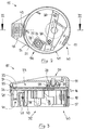
- FIG. 1 shows one through an essentially box-shaped plastic housing formed, closable by means of a hinged lid Shaft 1, which in particular also for partial or almost completely submerged in the soil suitable and determined is.
- the shaft can be connected via pipe connections that are parallel to the axis 2 on preferably slightly elastic plastic pipes a preferably underground water supply network be connected.
- a shaft of the type shown and its uses are for example in the German patent DE 39 24 795. Im limited by the housing walls Inside the shaft runs a connecting pieces 2 connecting Plastic pipe section 3, on the middle between the connectors an electromagnetically actuated to Interrupting the liquid flow provided in the pipe section 3 Shut-off valve 4 is screwed on.
- an electromagnet 5 is provided which is electrically connected to a not shown electrical power supply connected which includes an accumulator and which in one the valve 4 and the electromagnet 5 enclosing plastic housing 6 is housed.
- the electromagnetically switchable shut-off valve 4 forms one in the liquid flow of the pipe section 3 intervening device for executing a mechanical function, namely opening and closing a liquid passage. Together with the electromagnet and the power supply it forms a functional unit 10, also as a solenoid valve assembly or as a solenoid valve assembly referred to as.
- the functional unit 10 On top of a pot-shaped one, essentially cylindrical extension 11 the functional unit 10 is liquid-tight in the manner of a sealed power cord plug a completely electric and mechanically detachable control unit 15 attached.
- the hinged cover of the valve shaft is opened.
- closed state of the hinged lid lies there flat underside at a short distance above the flat top of the control unit 15, so that a loosening of the Control unit from the functional unit is not possible.
- in the 1 shown assembled state of the control unit and functional unit is that in FIGS. 2 and 3 shown interior of the control unit by a better in Fig. 3 Recognizable, essentially closed housing at the top 16 and by a cylindrical outer circumference Approach 17 of the control unit circumferential sealing ring 18, the presses against the cylindrical inside of the neck 11, completely sealed against external moisture.
- the control unit has a two-part plastic housing 16, that by one in Fig. 3 open downwards, one-sided beveled housing cover 19 and one by screws 20 screwed adapter 21 is formed, which can be plugged together with the cylindrical extension 11 of the functional unit 10 is provided. Between the two housing parts 19, 21, a circuit board 22 is clamped on the Housing cover 19 facing away from electronic components, not shown are attached. Through the through conductor tracks connected electronic components is the externally programmable Control unit 23 embodies the control unit.
- the electronic elements are for protection against moisture with a Layer 24 made of a moisture-proof plastic casting compound covered, which encloses the components and at the same time to mechanical stabilization of the circuit board arrangement contributes.
- the circuit board arrangement 22, 24 is during installation into the control unit on a rotating, step-shaped, inward projection 25 of the housing cover 19th placed and by screwing the one front projection 26 having adaptation part 21 fixed in position between Housing cover 19 and adapter 21 clamped.
- the control is therefore not a separate fastener, such as screws or the like.
- a The control can be replaced in a simple manner Unscrew the two housing parts 19, 21, take them out the controller 23 and replace it with another controller.
- a contact for manual in the embodiment shown Actuation of the control provided via a tip switch 27 can be operated.
- the tip switch 27 is than the top of the cover 19 slightly superior Rubber button formed on which an elastic cone 28 with an annular foot 29 which is approximately square in cross section is trained.
- the foot 29 is in the assembled state the housing parts by an annular extension 30 of the housing cover sealingly pressed onto the top of the circuit board and seals the contact point moisture-proof.
- the controller 23 can be operated manually via the actuator 27 are switched, for example to switch between a closed position and an open position of the shut-off valve 4.
- the tip switch 27 is with the lid open Easily accessible shaft.
- the electrical contacting of the on the printed circuit board 22nd housed electronic control 23 takes place essentially via two separate plug contact groups, which with the conductor tracks of the circuit board electrically connected are.
- the plug contacts are through the potting compound layer 24 held and protrude from the sealing compound side facing away from the cover. They are first electrical Contact means 35 for producing a detachable, signal-conducting first connection of the controller with complementary Contact means of the functional unit and preferably one Programming unit described later provided.
- right-angled contact foot 36 protrudes a cylindrical, metallic Contact sleeve 37 out, which is a little shorter axially surrounds round metallic contact pin 38.
- the coaxial connector 35 is used for the signal-conducting transmission of control signals from the controller 23 to that through the control signals controlled solenoid valve 4 when control unit 15 and functional unit 10 are put together. He continues to serve the signal-conducting electrical connection to a programming device, with which is embodied in the controller 23 Control program for the valve can be changed if necessary can.
- the control unit does not have its own electrical power supply for control.
- For connecting an external Power supply are in contact with the controller 23 standing second contact means protruding from the sealing compound 40 provided as sockets of a two-pole Flat plug contact are formed.
- the thru axles of the Coaxial connector 35 and the flat socket 40 are parallel, so that both electrical connections through a common Plug-in movement made parallel to the plug-in axles or can be solved.
- the functional unit 10 has with the Flat sockets 40 cooperating flat tongues, the electrical with the power supply of the functional unit are connected so that the power supply of the functional unit at the same time the power supply of the Control unit is when it is plugged onto the functional unit is. Because the control unit does not have its own electrical Power supply, it can be particularly light and can be manufactured inexpensively.
- the first contact means 35 and the spring-loaded second Contact means 40 of the control unit form a control unit contact arrangement, the one with an essentially mirror image arranged complementary functional unit contact arrangement cooperates.
- the electrical contact the plug connections alone can be enough Control unit and the functional unit also non-positively connect mechanically.
- the when making the plug contacts contact surfaces sliding against each other and rubbing against each other additionally cleanse themselves of each other Impurities, such as oxidation films, so that A good electric one at all times, even in a damp environment signal conducting and supply current conducting electrical Contact between control unit and functional unit guaranteed is.
- a detachable mechanical connection between the control unit and functional unit is continued through the forms of interlocking housing of control unit 15 and functional unit 10 created.
- the cylindrical approach 17 of the Adaption part 21 has an essentially cylindrical for this purpose Outside 41, the outside diameter of the inside diameter corresponds to the cylindrical extension 11 of the functional unit.
- control unit For a complete liquid-tight seal when plugged together, the control unit one around the neck 17 in a circumferential, semicircular Groove 42 lying sealing ring 18, when plugging together of control unit and functional unit to the inside of the Approach 11 is pressed and so the contact space is liquid-tight seals.
- the compressible sealing ring 18 promotes at the same time a positive mechanical connection between control unit and functional unit against pulling apart of components 10, 15.
- a two-pole socket 44 arranged, even in the assembled state is accessible from the control unit and functional unit.
- the Contacts 44 are connected to the controller 23 and serve the optional connection of an externally attachable moisture sensor. This can, for example, after extensive Give a signal to the controller in the event of rain, with which the Program run of a sprinkler interrupted and will be resumed later.
- the described embodiment of the invention is that in 4 assigned to the programming unit 45 shown schematically.
- the programming unit is as a portable, hand-held Programming device trained. This has one through two with each other screw-formed plastic housing shells 46, 47 formed Housing on which an internally hollow handle 48 is formed is. Inside the handle you can at least an accumulator or at least one battery for electrical Power supply to the programming device is provided be. 4 at the upper end of the handle 48 an essentially cylindrical housing head 49 is formed, whose axis is substantially perpendicular to the longitudinal axis of the Handle 48 runs.
- One for the operator when using facing flat back 50 of the housing head carries one Group of controls 51, in the example as liquid-tight push buttons sealed against the housing are.
- the status of the device is via an LCD display panel readable.
- the programming device has electrical contacts in a programming unit contact arrangement that the Functional unit contact arrangement corresponds. This can the control unit in one and the same way by plugging both with the functional unit 10 and with the programming unit 45 releasably electrically connected. Programming the control leads to programming Control signals provided by the housed in the housing 46, 47 Programming electronics via the first contact means 35 of the control device for control 23. At the same time the power supply accommodated in the handle 48 with the plug contacts 40 corresponding tongues electrically connected to the controller 23 so that the power supply the programming unit at the same time external power supply for the controller 23 of the control unit 15 is.
- the programming unit contact arrangement is by a cylindrical projection formed on the housing part 47 54 enclosed, the inside of which has the same shape and Dimension as the inside of the approach 11 has. Thereby are in contact with each other during programming standing electrical contacts through the seal 18 on the Control unit sealed against moisture from the outside.
- the contact areas of the programming device are therefore an advantage and solenoid valve in the embodiment shown at least identical in terms of electrical contact arrangements. This is compared to a separate one that is also possible Contacting the energy supply contacts on the one hand and the signal contacts on the other hand in the programming state advantageous because of the much easier handling.
- a preferred embodiment of the invention thus provides not only the unit of control electronics and functional unit, especially electromagnetic valve divide into one containing the functional device Assembly and a control electronics assembly releasably connected to it. It also becomes the previous unit of programming electronics and control electronics divided by in addition to the control electronics module, a separate programming module is provided.
- the electrical connection between the units takes place facing each other Plug contacts of the modules.
- the control electronics assembly is on their facing away from the valve or the programming device Side completely closed and therefore offers no attack for penetrating moisture.
- the mechanical connection of the circumferential seal supporting the assemblies protects the electrical contacts against moisture and simultaneously supports the frictional mechanical Connection of control unit and functional unit and preferably also of control unit and programming unit.
Abstract
Description
Die Erfindung betrifft eine Vorrichtung zur programmgesteuerten Ausführung einer Funktion, insbesondere ein programmgesteuertes Ventil zur Steuerung eines Flüssigkeitsstromes in einer Wasserleitung einer Gartenbewässerungsanlage.The invention relates to a device for program-controlled Execution of a function, in particular a program-controlled one Valve for controlling a liquid flow in a water pipe of a garden irrigation system.
Gattungsgemäße Vorrichtungen führen eine oder mehrere mechanische Funktionen aus, die insbesondere nach einem vorgebbaren Zeitprogramm ablaufen können. Typische Anwendungsbeispiele im Bereich der Haus- und Gartenbewässerung sind programmgesteuerte Beregnungsvorrichtungen oder programmgesteuerte Absperr- und/oder Verteilungsventile, die in Flüssigkeits-Leitungen und/oder Flüssigkeits-Leitungsnetzen vorgesehen sind. Eine gattungsgemäße Vorrichtung hat eine mittels einer Programmeinrichtung programmierbare elektronische Steuerung zur Abgabe von elektrischen Steuersignalen und eine durch die Steuersignale ansteuerbare, vorzugsweise elektrisch betreibbare Einrichtung zur Ausführung der Funktion.Generic devices carry one or more mechanical Functions that, in particular, according to a specifiable Time program can run. Typical application examples in the area of house and garden irrigation are program-controlled Irrigation devices or program-controlled Shut-off and / or distribution valves used in liquid lines and / or liquid line networks are provided are. A generic device has a means a programmable electronic programmable device Control for the delivery of electrical control signals and a controlled by the control signals, preferably electrically operable device for performing the function.
Eine aus der US-Patentschrift 4 108 419 bekannte gattungsgemäße Vorrichtung ist ein Ventil eines automatischen Beregnungssystems. Die Steuerung des Ventils sowie die zur Programmierung der Steuerung vorgesehene Programmiereinrichtung sind in einem von dem eigentlichen Ventilgehäuse abnehmbaren Gehäusekopf untergebracht, in dem auch die Batterien zur elektrischen Leistungsversorgung der Programmier- und Steuereinheit untergebracht sind. An dem abnehmbaren Gehäusekopf sind Drehschalter zur manuellen Einstellung des jeweils gewünschten Beregnungs-Zeitprogrammes vorgesehen. Die vom Ventilgehäuse abnehmbare Steuer- und Programmiereinheit ist relativ schwer und groß und wegen ihres komplexen Aufbaus in der Herstellung teuer. Die Anzahl der über die Drehknöpfe anwählbaren, in einer elektronischen Schaltung verkörperten Programme ist begrenzt.A generic type known from US Pat. No. 4,108,419 Device is a valve of an automatic irrigation system. The control of the valve and that for programming programming device provided to the control are in a removable from the actual valve housing Housing head housed, in which the batteries for electrical power supply of the programming and control unit are accommodated. On the removable housing head are rotary switches for manual setting of the desired one Irrigation time program provided. The one from the valve body removable control and programming unit is relative heavy and large and because of their complex structure in expensive to manufacture. The number of over the knobs selectable, embodied in an electronic circuit Programs is limited.
Ähnlich kompliziert aufgebaute, von angesteuerten Flüssigkeitsventilen abnehmbare kombinierte Steuer- und Programmiereinheiten sind auch aus der europäischen Patentschrift EP 0 236 535 und aus der Veröffentlichung BUREAUX D'ETUDES AUTOMATISMES, Nr. 19, September 1985, Seite 19, Paris, FR; "Arrosage programmé et capteurs en bois", bekannt.Similarly complex, controlled by liquid valves removable combined control and programming units are also from the European patent EP 0 236 535 and from the publication BUREAUX D'ETUDES AUTOMATISMES, No. 19, September 1985, page 19, Paris, FR; "Arrosage program et capteurs en bois", known.
Bei den bekannten Steuer- und Programmiereinheiten ist die Anzahl der in ihren Steuerungen verkörperten Programme begrenzt. Zwischen den Programmen kann gewählt werden, die Programme selbst sind jedoch nicht veränderbar. Wenn die Funktion nach einem anderen, nicht eingebauten Programm ablaufen soll, dann muß die gesamte Programmier- und Steuereinheit ersetzt werden. Wird eine Reparatur oder eine Ersetzung der in feuchter Umgebung ggf. störanfälligen Programmier- und Steuereinheit notwendig, so muß ebenfalls die gesamte Baugruppe ausgebaut und ggf. als Ganzes ersetzt werden.In the known control and programming units Limited number of programs embodied in their controls. You can choose between the programs However, programs themselves cannot be changed. If the Execute function according to another, not built-in program then the entire programming and control unit be replaced. Will a repair or a replacement the programming and control unit, which may be susceptible to faults in a damp environment, must also cover the entire Module removed and possibly replaced as a whole.
Der Erfindung liegt die Aufgabe zugrunde, eine gattungsgemäße Vorrichtung zu schaffen, die wirtschaftlich herstellbar und bei nur geringem Bedienungsaufwand variabel einsetzbar ist. Insbesondere soll die Vorrichtung auch wartungs- und reparaturfreundlich sein und/oder es soll eine einfache, ortsungebundene Programmierung, beispielsweise am Ort einer im Garten fest installierten Funktionseinheit ermöglicht werden.The invention has for its object a generic To create device that is economical to manufacture and can be used variably with only a small amount of operation. In particular, the device should also be easy to maintain and repair and / or it should be a simple, location-independent Programming, for example at the location of an Garden fixed functional unit can be enabled.
Zur Lösung dieser Aufgabe schlägt die Erfindung eine Vorrichtung
mit den Merkmalen von Anspruch 1 vor.To achieve this object, the invention proposes a device
with the features of
Nach der Erfindung ist die Steuerung einer Steuereinheit zugeordnet, die ggf. ausschließlich aus der Steuerung bestehen kann, normalerweise aber weitere funktionelle Teile, jedoch keine Programmiereinrichtung enthält. Die Steuereinheit ist mechanisch und elektrisch lösbar mit einer die Einrichtung aufweisenden Funktionseinheit verbindbar. Die Funktionseinheit kann im wesentlichen ausschließlich die anzusteuernde Einrichtung umfassen, enthält aber in der Regel weitere funktionelle Teile. Die Programmiereinrichtung ist einer separaten Programmiereinheit zugeordnet, die mechanisch und elektrisch lösbar mit der Steuereinheit verbindbar ist und die vorzugsweise auch separat von der Funktionseinheit ist. Die Vorrichtung nach der Erfindung ist modular aufgebaut. Die zusammenwirkenden Module, d.h. die Steuereinheit, die Programmiereinheit und die Funktionseinheit können insbesondere vollständig elektrisch und mechanisch voneinander getrennt werden.According to the invention, the control is assigned to a control unit, which may consist solely of the controller can, but usually other functional parts, however contains no programming device. The control unit is mechanically and electrically detachable with a device having functional unit connectable. The functional unit can essentially only be controlled Facility include, but usually contains more functional parts. The programming device is one assigned separate programming unit, the mechanical and is electrically releasably connectable to the control unit and which is preferably also separate from the functional unit. The device according to the invention has a modular structure. The interacting modules, i.e. the control unit, the programming unit and the functional unit can in particular completely electrically and mechanically separated become.
Die durch die Programmiereinheit programmierbare Steuerung der Steuereinheit kann vorteilhaft mit einer Vielzahl verschiedener Funktionseinheiten verwendet werden. Die Steuereinheit kann z.B. von einem Flüssigkeitsventil abgenommen und, ggf. nach Umprogrammierung, zur Steuerung einer Pumpe, einer Gartenbeleuchtung, einer Balkonbewässerung oder als Schalterersatz an einer Wand oder dergleichen eingesetzt werden. Zur Programmierung kann jeweils die gleiche Programmiereinheit genutzt werden.The controller programmable by the programming unit the control unit can advantageously be used with a variety of different Functional units are used. The control unit can e.g. removed from a liquid valve and, if necessary after reprogramming, to control a pump, garden lighting, balcony watering or as Switch replacement used on a wall or the like become. The same programming unit can be used for programming be used.
Die Funktionseinheit kann beispielsweise ein in einer Flüssigkeitsleitung fest oder lösbar eingebautes Ventil umfassen. Der Verbleib der Funktionseinheit an ihrem Funktionsort ist bei fest mit einem Leitungssystem verbundenen Ventilen praktisch unumgänglich. Auch bei lösbarer Verbindung sollte sie jedoch nur in Ausnahmefällen gelöst werden, da sonst unter Umständen bei der Wiederherstellung der Verbindung Dichtigkeitsprobleme auftreten können. Bei einer erfindungsgemäßen Vorrichtung kann die Funktionseinheit an dem Leitungssystem verbleiben, während die Steuereinheit weggenommen und ggf. weit entfernt von der Funktionseinheit repariert oder umprogrammiert oder ggf. gegen eine andere Steuereinheit ausgewechselt werden kann. Mit Vorteil kann eine Neuprogrammierung einfach durch Austausch einer Steuerung durch eine nach einem anderen Programm arbeitende Steuerung erfolgen, was zum Beispiel bei Umsteigen auf eine neuere Version einer Steuerung oder eines Programmes von Vorteil ist. Die Funktionseinheit und die Programmiereinheit können unverändert weiterverwendet werden. Die gleichen Vorteile sind auch beim Austausch defekter Steuerungen oder bei einem Ausbau der Steuerungen für eine eingehende Funktionsprüfung im Rahmen von Wartungsarbeiten erzielbar. Da die Steuereinheit die programmierbare Steuerung, nicht aber die zu ihrer Programmierung vorgesehene Programmiereinrichtung enthält, kann sie sehr kostengünstig hergestellt werden und leicht und kompakt sein. Ein ggf. erforderlicher Austausch einer defekten Steuerung erfaßt nicht die Programmiereinrichtung, was zum Beispiel aus Gründen der Wirtschaftlichkeit und des Umweltschutzes von Vorteil ist.The functional unit can, for example, be in a liquid line include a fixed or detachable valve. The functional unit remains at its functional location practical for valves permanently connected to a line system inevitable. Even with a detachable connection, it should but can only be solved in exceptional cases, otherwise under Circumference problems when restoring the connection may occur. In an inventive Device can be the functional unit on the line system remain while the control unit is removed and possibly repaired or reprogrammed far from the functional unit or, if necessary, exchanged for another control unit can be. Reprogramming can be advantageous simply by replacing a controller with one after another other program working control, what for example when changing to a newer version of a controller or a program is an advantage. The functional unit and the programming unit can continue to be used unchanged become. The same advantages are also defective when replacing Controls or if the controls are expanded for an in-depth functional test as part of maintenance work achievable. Since the control unit is the programmable controller, but not the one intended for their programming Contains programming device, it can be very inexpensive be made and be light and compact. A possibly necessary Replacement of a defective control does not record the programming device, which for example for the sake of Economy and environmental protection is an advantage.
Es ist möglich, die zusammenwirkenden Module mittels einer oder mehrerer Schrauben zu verbinden. Bei einer bevorzugten Ausführungsform ist vorgesehen, daß die Steuereinheit werkzeuglos, d.h. ohne Zuhilfenahme von Werkzeugen wie Schraubendrehern oder dergleichen, mit der Funktionseinheit und/oder der Programmiereinheit verbindbar und/oder werkzeuglos von diesen lösbar ist. Bei solchen Ausführungsformen ist der Bedienungsaufwand beim Abnehmen bzw. Anbringen der Steuereinheit an der Funktionseinheit und/oder der Programmiereinheit besonders gering.It is possible to use the interacting modules or several screws to connect. In a preferred one Embodiment is provided that the control unit without tools, i.e. without the use of tools such as screwdrivers or the like, with the functional unit and / or connectable to the programming unit and / or without tools from this is solvable. In such embodiments, the operating effort when removing or attaching the control unit on the functional unit and / or the programming unit particularly low.
Vorzugsweise kann die Steuereinheit an oder in der Funktionseinheit und/oder der Programmiereinheit festklemmbar sein. Dazu können an der Funktionseinheit bzw. der Programmiereinheit und/oder an der Steuereinheit gesonderte zusammenwirkende Klemmeinrichtungen vorgesehen sein. Vorzugsweise sind die Steuereinheit und die Funktionseinheit und/oder die Programmiereinheit selbst derart ausgebildet, daß sie aneinander festklemmbar, insbesondere aneinander feststeckbar sind. Es kann mindestens ein elastisches Element zur kraftschlüssigen Halterung der Steuereinheit an der Funktionseinheit und/oder der Programmiereinheit vorgesehen sein, das vorzugsweise ein elastisch komprimierbares Dichtelement wie zum Beispiel ein Kunststoff-O-Ring sein kann. Die mechanische Verbindung der Module kann ausschließlich durch eine kraftschlüssige Verbindung, beispielsweise ein Verklemmen gegen Auseinanderziehen der Bauteile bewirkt werden. Alternativ oder zusätzlich kann die Steuereinheit mit der Funktionseinheit und/oder der Programmiereinheit formschlüssig verbindbar sein, beispielsweise durch Klammern oder Schrauben. Eine formschlüssige Verbindung kann zuverlässig ein unbeabsichtigtes Lösen von Steuereinheit und Funktionseinheit bzw. Programmiereinheit verhindern.The control unit can preferably be on or in the functional unit and / or the programming unit can be clamped. You can do this on the functional unit or the programming unit and / or separate cooperating on the control unit Clamping devices may be provided. Preferably, the Control unit and the functional unit and / or the programming unit themselves trained so that they meet each other can be clamped, in particular can be plugged together. It can have at least one elastic element for non-positive Holder of the control unit on the functional unit and / or the programming unit may be provided, preferably a elastically compressible sealing element such as a Plastic o-ring can be. The mechanical connection of the Modules can only be connected by a positive connection, for example jamming against pulling apart of the components are effected. Alternatively or in addition the control unit with the functional unit and / or the programming unit be positively connectable, for example by clamps or screws. A positive connection can reliably prevent accidental loosening of control unit and prevent functional unit or programming unit.
Eine Ausführungsform zeichnet sich dadurch aus, daß die Steuereinheit ein die Steuerung mindestens bereichsweise flüssigkeitsdicht abdeckendes Gehäuse hat, welches vorzugsweise aus Kunststoff besteht. Das Gehäuse kann mehrteilig sein und insbesondere zwei lösbar miteinander verbindbare, vorzugsweise miteinander verschraubbare Gehäuseteile aufweisen. Das Gehäuse bzw. die Gehäuseteile können im Spritzgußverfahren hergestellt sein. Ein die Steuerung mindestens teilweise umschließendes Gehäuse kann diese weitgehend vor Beschädigungen schützen. Bei einem mehrteiligen Gehäuse kann die Steuerung durch die mechanische Verbindung der Gehäuseteile klemmend am Gehäuse festgelegt werden, wodurch gesonderte Befestigungsmittel für die Steuerung im Gehäuse entfallen können.One embodiment is characterized in that the control unit a the control is liquid-tight at least in some areas covering housing, which is preferably made of Plastic is made. The housing can be in several parts and in particular two releasably connectable, preferably have screwed housing parts. The housing or the housing parts can be injection molded be. A control that at least partially encloses the control Housing can largely prevent this from damage protect. With a multi-part housing, the control can due to the mechanical connection of the housing parts Housing are fixed, creating separate fasteners for control in the housing can be omitted.
Die Steuerung kann mindestens bereichsweise feuchtedicht versiegelt sein, wobei die Steuerung vorzugsweise als Leiterplatte mit elektronischen Bauelementen ausgebildet ist, die von einer feuchtedichten Vergußmasse umgeben sind. Die Vergußmasse kann die mit den Bauteilen bestückte Seite der Leiterplatte vorzugsweise vollständig bedecken und ggf. die gegenüberliegende, mit Leiterbahnen versehene Seite zur Kontaktierung frei lassen. Eine fest in Kontakt mit der Leiterplatte stehende Schicht aus Vergußmaterial stabilisiert die Leiterplatte zusätzlich mechanisch.The control can be sealed moisture-proof at least in some areas be, the controller preferably as a printed circuit board is formed with electronic components that are surrounded by a moisture-proof sealing compound. The potting compound can the side of the circuit board equipped with the components preferably cover completely and, if necessary, the opposite side with conductor tracks for contacting set free. One firmly in contact with the circuit board standing layer of potting material stabilizes the PCB mechanically.
Die Steuereinrichtung kann mindestens ein Betätigungsglied zur manuellen Schaltung der Steuerung haben, über das beispielsweise ein Ventil von einer Sperrstellung in eine Durchlaßstellung und zurück umgeschaltet werden kann. Es ist auch möglich, ein oder mehrere Betätigungsglieder derart mit der Schaltung zu koppeln, daß über die Betätigungsglieder das Steuerprogramm ein- oder ausgeschaltet wird und/oder daß zwischen verschiedenen Steuerprogrammen umgeschaltet werden kann. Das Betätigungsglied kann über eine Gehäusewand des Gehäuses der Steuereinheit hinausragen. Ein Betätigungsglied kann insbesondere als Tipp-Schalter ausgebildet sein. Vorzugsweise ist es derart flüssigkeitsdicht abgedichtet, daß im Bereich des Betätigungsgliedes keine Flüssigkeit in das Gehäuse eindringen kann.The control device can have at least one actuator have to manually switch the control, for example a valve from a blocking position to a open position and can be switched back. It is also possible one or more actuators in such a way with the To couple circuit that over the actuators Control program is turned on or off and / or that can be switched between different control programs can. The actuator can via a housing wall of the housing protrude from the control unit. An actuator can be designed in particular as a tip switch. Preferably it is sealed so liquid-tight that no liquid in the area of the actuator Housing can penetrate.
Zur Ausübung der Steuerungsfunktion muß die Steuerung signalleitend, insbesondere elektrisch leitend mit der Einrichtung verbunden werden. Dazu hat bei einer bevorzugten Ausführungsform die Steuereinheit erste Kontaktmittel zur Herstellung einer lösbaren, signalleitenden elektrischen ersten Verbindung der Steuerung mit der Einrichtung. Die erste Verbindung ist dazu vorgesehen, Signalspannungen zu übertragen. Die Einrichtung ist mit entsprechenden komplementären Kontaktmitteln ausgestattet, die zum Zusammenwirken mit den die Steuersignale übertragenden ersten Kontaktmitteln ausgebildet sind. Eine Weiterbildung der Erfindung sieht vor, daß die ersten Kontaktmittel als Teil einer ersten elektrischen Steckverbindung ausgebildet sind, wobei die ersten Kontaktmittel vorzugsweise als Teil einer vorzugsweisen zweipoligen Koaxial-Steckverbindung ausgebildet sind. Vorzugsweise ist ein innerer Kontaktstift vorgesehen, der von einer äußeren Kontakthülse umgeben ist. Eine Koaxial-Steckverbindung für die Signalleitung ist besonders unanfällig gegen insbesondere elektromagnetische Störungen. Die korrspondierenden Kontaktmittel der Funktionseinheit sind komplementär ausgebildet. Sie weisen insbesondere eine zur Kontaktierung des Kontaktstiftes vorgesehene zentrische Hülse und eine zum Ineinanderschieben mit der Kontakthülse vorgesehene äußere Hülse auf. Die Anordnung von Steckern auf der einen und Buchsen auf der anderen Seite der Steckverbindung ist jedoch auch umgekehrt möglich. Die erste Steckverbindung bewirkt neben der elektrischen Verbindung auch eine kraftschlüssige mechanische Verbindung der Module, so daß ggf. gesonderte mechanische Verbindungsmittel entfallen können. To perform the control function, the control must be signal-conducting, in particular electrically conductive with the device get connected. To do this in a preferred embodiment the control unit produces first contact means a detachable, signal-conducting electrical first connection the control with the facility. The first connection is intended to transmit signal voltages. The Establishment is with appropriate complementary contact means equipped to interact with the Control signals transmitting first contact means formed are. A further development of the invention provides that the first contact means as part of a first electrical Plug connection are formed, the first contact means preferably as part of a preferred bipolar Coaxial connector are formed. Preferably an inner contact pin is provided by an outer one Contact sleeve is surrounded. A coaxial connector for the signal line is particularly insensitive to in particular electromagnetic interference. The corresponding contact means the functional unit are complementary. They particularly have one for contacting the Contact pin provided central sleeve and one for Push one into the other provided with the contact sleeve Sleeve on. The arrangement of plugs on one and However, there are sockets on the other side of the connector also possible vice versa. The first connector causes in addition to the electrical connection also a non-positive connection mechanical connection of the modules, so that if necessary separate mechanical connecting means can be omitted.
Es ist möglich, für die Steuerung eine eigene Leistungsversorgung vorzusehen, beispielsweise eine im Gehäuse der Steuereinheit untergebrachte Batterie. Bei einer bevorzugten Ausführungsform hat die Steuereinheit keine eigene elektrische Leistungsversorgung für die Steuerung. Eine derartige Steuereinheit ist besonders kompakt und kostengünstig herstellbar und eine ggf. erforderliche Auswechslung der Steuereinheit erfaßt nicht die Leistungsversorgung für die Steuereinheit. Bei einer bevorzugten Ausführungsform hat die Steuereinheit zweite Kontaktmittel zur Herstellung einer lösbaren zweiten elektrischen Verbindung der Steuerung mit einer externen Leistungsversorgung, beispielsweise einem Akkumulator oder einer Batterie. Die zweite elektrische Verbindung ist vorzugsweise für Übertragung von Gleichspannungen im Volt-Bereich ausgelegt. Es ist bevorzugt, wenn die zweiten Kontaktmittel als Teil einer zweiten elektrischen Steckverbindung ausgebildet sind. Die zweite Steckverbindung kann eine insbesondere zweipolige Flach-Steckverbindung sein. Vorzugsweise sind mit der Steuerung Flach-Steckbuchsen verbunden, die zum Zusammenwirken mit entsprechenden flachen Steckzungen ausgebildet sind, die in Kontakt mit der externen Leistungsversorgung stehen. Auch hier ist die Anordnung von Steckern auf der einen und Buchsen auf der anderen Seite der zweiten Steckverbindung umkehrbar.It is possible for the control to have its own power supply to provide, for example one in the housing of Control unit housed battery. In a preferred one The control unit does not have its own electrical embodiment Power supply for the control. Such Control unit is particularly compact and inexpensive to manufacture and a possibly necessary replacement of the control unit does not detect the power supply for the control unit. In a preferred embodiment, the control unit second contact means for producing a detachable second electrical connection of the control with an external Power supply, for example an accumulator or a battery. The second electrical connection is preferably for the transmission of direct voltages in the volt range designed. It is preferred if the second contact means as part of a second electrical connector are trained. The second connector can in particular be two-pin flat connector. Preferably are connected to the control flat sockets, which for Interaction with corresponding flat tabs trained who are in contact with the external power supply stand. Again, the arrangement of plugs on the one and sockets on the other side of the second connector reversible.
Die Leistungsversorgung für die Steuerung und/oder die Funktionseinheit kann gesondert von der Steuereinheit und ggf. gesondert von der Funktionseinheit angeordnet sein. Vorzugsweise hat die Funktionseinheit eine vorzugsweise netzunabhängige eigene Leistungsversorgung für die Einrichtung, die insbesondere mindestens einen Akkumulator umfaßt. Diese Leistungsversorgung stellt die elektrische Energie zum Betreiben der elektrischen Einrichtung zur Ausführung der gewünschten Funktion zur Verfügung. Vorzugsweise ist die Leistungsversorgung der Funktionseinheit gleichzeitig eine externe Leistungsversorgung für die Steuereinheit. Die Leistungsversorgung kann hierzu elektrisch mit Kontaktmitteln verbunden sein, die zum Zusammenwirken mit den zweiten Kontaktmitteln der Steuereinheit ausgebildet sind. Bei der Verbindung von Steuereinheit und Funktionseinheit kann über die Kontaktmittel eine elektrische Verbindung der Leistungsversorgung der Funktionseinheit zur Steuerung hergestellt werden.The power supply for the control and / or the functional unit can be separated from the control unit and if necessary be arranged separately from the functional unit. Preferably the functional unit has a preferably network-independent one own power supply for the facility, in particular comprises at least one accumulator. This power supply provides the electrical energy for operation the electrical device to carry out the desired Function available. The power supply is preferred an external power supply to the functional unit for the control unit. The power supply can be electrically connected to contact means be to interact with the second contact means the control unit are formed. When connecting Control unit and functional unit can via the contact means an electrical connection of the power supply Functional unit to be manufactured for control.
Eine externe Programmiereinrichtung muß nur bei der Programmierung mit der Steuerung verbunden sein und kann während des normalen Betriebes der Vorrichtung gesondert von dieser aufbewahrt oder ggf. zur Programmierung anderer Steuerungen eingesetzt werden. Es ist möglich, die Programmiereinrichtung über einen speziell für die Programmierung vorgesehenen elektrischen Anschluß mit der Steuerung zu verbinden. Bei einer bevorzugten Ausführungsform hat die Programmiereinheit elektrische Kontaktmittel, die zum Zusammenwirken mit den ersten Kontaktmitteln der Steuereinheit ausgebildet sind, insbesondere als Teil einer Koaxial-Steckverbindung. Diese Kontaktmittel sind mit der signalgebenden Elektronik der Programmiereinrichtung verbunden. Dadurch ist es möglich, den Kontakt, der im Betrieb der Vorrichtung zur Übertragung von Signalen zwischen Steuereinheit und Funktionseinheit verwendet wird, ebenfalls für die Programmierung zu verwenden. Ein gesonderter Anschluß an der Steuereinheit, der ggf. gesondert abgedichtet werden müßte, kann daher entfallen. Die Kontaktmittel der Programmiereinheit können an einem an die Programmiereinheit anschließbaren Kabel vorgesehen sein, sind jedoch vorzugsweise direkt an einem Gehäuse der Programmiereinheit vorgesehen.An external programming device only has to be used for programming connected to the controller and can be used during the normal operation of the device separately from this stored or possibly for programming other controls be used. It is possible to use the programming device via a specially designed for programming to connect the electrical connection to the control. At the programming unit has a preferred embodiment electrical contact means that interact with the first contact means of the control unit are formed, especially as part of a coaxial connector. This Contact means are with the signaling electronics of the Programming device connected. This makes it possible to Contact that is in operation of the device for the transmission of Signals used between the control unit and functional unit will also be used for programming. A separate connection to the control unit, which may be separate should be sealed, can therefore be omitted. The means of contact the programming unit can be connected to the Programming unit connectable cables are provided however, preferably directly on a housing of the programming unit intended.
Eine bevorzugte Programmiereinheit hat eine vorzugsweise netzunabhängige eigene Leistungsversorgung, die vorzugsweise mindestens einen Akkumulator umfaßt. Die Leistungsversorgung der Programmeinheit kann mit Vorteil elektrisch mit Kontaktmitteln verbunden sein, die zum Zusammenwirken mit den zweiten Kontaktmitteln der Steuereinheit ausgebildet sind, insbesondere Flach-Steckzungen. Eine derartige Ausführung ermöglicht es, die Leistungsversorgung der Programmiereinheit als Leistungsversorgung der Steuereinheit zu verwenden, insbesondere bei der Programmierung der Steuerung. Die elektrische Verbindung der elektrischen Kontakte der Programmiereinrichtung mit denen der Steuereinheit kann über Kabel erfolgen. Vorzugsweise erfolgt sie jedoch kabellos. Insbesondere kann die Programmiereinheit derart ausgebildet sein, daß sie mechanisch und elektrisch lösbar mit der Steuereinheit verbindbar, insbesondere zusammensteckbar ist. Sie kann gleichzeitig als Halterung für die Steuereinheit während der Programmierung wirken.A preferred programming unit preferably has one independent power supply, preferably comprises at least one accumulator. The power supply the program unit can advantageously be electrically with contact means be connected to cooperate with the second Contact means of the control unit are formed, in particular Flat tabs. Such an execution enables it, the power supply to the programming unit as Power supply to use the control unit, in particular when programming the control. The electrical Connection of the electrical contacts of the programming device with those of the control unit can be done via cable. However, it is preferably wireless. In particular, can the programming unit be designed such that it is mechanical and can be electrically detachably connected to the control unit, is particularly pluggable. It can at the same time as a holder for the control unit during programming Act.
Diese sehr einfache Handhabung wird unter anderem dadurch gefördert, daß die ersten Kontaktmittel und die zweiten Kontaktmittel der Steuereinrichtung eine Steuereinrichtungs-Kontaktanordnung bilden, die zum Zusammenwirken mit einer komplementären Funktionseinheits-Kontaktanordnung der Funktionseinheit ausgebildet ist. Vorzugsweise hat die Programmiereinrichtung eine Programmiereinrichtungs-Kontaktanordnung, die im wesentlichen der Funktionseinheits-Kontaktanordnung entspricht, so daß die Steuereinrichtung in gleicher Weise sowohl an die Funktionseinheit wie an die Programmiereinrichtung elektrisch angeschlossen werden kann.This makes it very easy to use promoted that the first contact means and the second contact means the control device a control device contact arrangement form that to interact with a complementary functional unit contact arrangement of the functional unit is trained. The programming device preferably has a programmer contact arrangement, which is essentially the functional unit contact arrangement corresponds so that the control device in the same Way to both the functional unit and the programming device can be connected electrically.
Zur Programmierung können an sich beliebige Programmiereinrichtungen vorgesehen sein, da die Programmierung nicht am Ort der Funktionseinheit vorgenommen werden muß. Es kann beispielsweise ein ortsfestes Programmiergerät vorgesehen sein, über welches beispielsweise eine Programmierung unter Verwendung eines Computers erfolgen kann. Vorzugsweise ist die Programmiereinheit als tragbares, vorzugsweise handgehaltenes Programmiergerät ausgebildet. Sie kann einen hohlen Handgriff aufweisen, in dem beispielsweise Batterien oder Akkumulatoren zur Leistungsversorgung der Programmiereinheit und ggf. einer an die Programmiereinheit angeschlossenen Steuereinheit vorgesehen sind. Durch eine tragbare Programmiereinrichtung kann die Programmierung der Steuereinheit direkt am Einsatzort der Vorrichtung vorgenommen werden, indem lediglich die Steuereinheit von der Funktionseinheit abgenommen und an das Programmiergerät angeschlossen bzw. angekoppelt und nach Abschluß der Programmierung wieder an die Funktionseinheit angeschlossen bzw. angekoppelt wird.Any programming device per se can be used for programming be provided because the programming is not on Location of the functional unit must be made. It can for example, a fixed programming device is provided be used for programming under Use of a computer can be done. Preferably the programming unit as a portable, preferably hand-held Programming device trained. It can be hollow Have handle in which, for example, batteries or Accumulators for supplying power to the programming unit and possibly one connected to the programming unit Control unit are provided. Through a portable programming device can program the control unit be carried out directly at the place of use of the device by only the control unit from the functional unit removed and connected to the programming device or coupled and on again after completing programming the functional unit is connected or coupled.
Bei einer bevorzugten Ausführungsform ist es von besonderem Vorteil, daß die erste elektrische Verbindung und die zweite elektrische Verbindung durch eine einzige Relativbewegung der Steuereinheit relativ zur Funktionseinheit oder zu der Programmiereinheit in eine gemeinsame Verbindungsrichtung lösbar oder herstellbar ist. Die ersten und die zweiten Kontaktmittel werden dadurch im wesentlichen gleichzeitig mit den korrespondierenden Kontaktmitteln von Funktionseinheit oder Programmiereinheit elektrisch verbunden. Vorzugsweise reicht eine im wesentlichen geradlinige Steckbewegung in einer gemeinsamen Steckrichtung aus. Hierzu sind die Steckachsen der ersten und der zweiten Steckverbindung im wesentlichen parallel.In a preferred embodiment, it is special Advantage that the first electrical connection and the second electrical connection by a single relative movement of the Control unit relative to the functional unit or to the programming unit releasable in a common connection direction or is producible. The first and the second contact means are thereby essentially simultaneously with the corresponding ones Contact means of the functional unit or programming unit electrically connected. Preferably enough an essentially straight plug-in movement in a common Direction of insertion. For this, the thru axles of the first and the second connector substantially parallel.
Insbesondere bei Einsätzen in feuchter oder nasser Umgebung, beispielsweise im Bereich von Bewässerungsanlagen und/oder dort, wo die Funktionseinrichtung teilweise oder ganz im ggf. feuchten Erdreich eingegraben ist, ist eine Ausführungsform von Vorteil, bei der die erste elektrische Verbindung und/oder die zweite elektrische Verbindung im verbundenen Zustand von Steuereinheit und Funktionseinheit und vorzugsweise auch dann, wenn Steuereinheit und Programmiereinheit verbunden sind, flüssigkeitsdicht abgedichtet sind. Hierzu können für jede Verbindung gesonderte Dichteinrichtungen vorgesehen sein, vorzugsweise erfolgt die Abdichtung jedoch durch eine die erste und die zweite elektrische Verbindung gemeinsam umschließende Dichteinrichtung. Die Dichteinrichtung kann vorzugsweise ein elastisch kompressibles Dichtelement, wie einen O-Ring, aufweisen, der neben der Dichtfunktion auch eine Funktion im Rahmen einer kraftschlüssigen Halterung der Steuereinheit an der Funktionseinheit bzw. an der Programmiereinheit ausübt.Especially when used in damp or wet environments, for example in the area of irrigation systems and / or where the functional device is partially or completely in the is buried in moist soil is one embodiment advantageous in which the first electrical connection and / or the second electrical connection in the connected state of control unit and functional unit and preferably also then when control unit and programming unit are connected are sealed liquid-tight. You can do this for each connection provided separate sealing devices be, but preferably the seal is made by a the first and the second electrical connection together enclosing sealing device. The sealing device can preferably an elastically compressible sealing element, such as have an O-ring, which in addition to the sealing function a function in the context of a non-positive holder of the Control unit on the functional unit or on the programming unit exercises.
Weitere Merkmale und Einzelheiten der Erfindung ergeben sich aus der nachfolgenden Beschreibung einer bevorzugten Ausführungsform in Verbindung mit den Zeichnungen und den Unteransprüchen. Hierbei können die einzelnen Merkmale jeweils für sich allein oder zu mehreren in Kombination miteinander bei einer Ausführungsform verwirklicht sein. Ausführungsbeispiele der Erfindung werden in den Zeichnungen dargestellt und im folgenden näher erläutert. In den Zeichnungen zeigen:
- Fig. 1
- eine Seitenansicht in teilweisem Schnitt einer Ausführungsform der Erfindung, bei der die Funktionseinheit ein in einem Ventilschacht angeordnetes elektromagnetisches Flüssigkeits-Absperrventil ist,
- Fig. 2
- eine Draufsicht auf die in Fig. 1 gezeigte Steuereinheit von der Seite der zur Verbindung mit der Funktionseinheit vorgesehenen elektrischen Kontaktanordnung,
- Fig. 3
- einen Querschnitt durch die Steuereinheit entlang der Linie III-III in Fig. 2, und
- Fig. 4
- eine schematische, perspektivische Ansicht
einer bevorzugten Ausführungsform einer Programmiereinheit
für die Steuereinheit in
den Figuren 1 bis 3.
- Fig. 1
- 2 shows a side view in partial section of an embodiment of the invention in which the functional unit is an electromagnetic liquid shut-off valve arranged in a valve shaft,
- Fig. 2
- 1 shows a top view of the control unit shown in FIG. 1 from the side of the electrical contact arrangement provided for connection to the functional unit,
- Fig. 3
- a cross section through the control unit along the line III-III in Fig. 2, and
- Fig. 4
- 2 shows a schematic, perspective view of a preferred embodiment of a programming unit for the control unit in FIGS. 1 to 3.
Die teilweise geschnittene Seitenansicht in Fig. 1 zeigt
einen durch ein im wesentlichen kastenförmiges Kunststoff-Gehäuse
gebildeten, mittels eines Klappdeckels verschließbaren
Schacht 1, der insbesondere auch zur teilweisen oder fast
vollständigen Versenkung in Erdreich geeignet und bestimmt
ist. Der Schacht kann über achsparallele Rohr-Anschlußstücke
2 an vorzugsweise geringfügig elastische Kunststoff-Rohrleitungen
eines vorzugsweise unterirdich verlegbaren Wasserleitungsnetzes
angeschlossen werden.The partially sectioned side view in Fig. 1 shows
one through an essentially box-shaped plastic housing
formed, closable by means of a hinged
Ein Schacht der gezeigten Art und seine Verwendungsmöglichkeiten
sind beispielsweise in der deutschen Patentschrift DE
39 24 795 beschrieben. Im durch die Gehäusewände begrenzten
Inneren des Schachtes verläuft ein die Anschlußstücke 2 verbindendes
Kunststoff-Rohrstück 3, an dem etwa mittig zwischen
den Anschlußstücken ein elektromagnetisch betätigbares, zum
Unterbrechen des Flüssigkeitsstromes im Rohrstück 3 vorgesehenes
Absperrventil 4 angeschraubt ist. Zur Schaltung des
Absperrventils zwischen Schließstellung und Durchlaßstellung
ist ein Elektromagnet 5 vorgesehen, der elektrisch mit einer
nicht gezeigten elektrischen Leistungsversorgung verbunden
ist, die einen Akkumulator umfaßt und die in einem das Ventil
4 und den Elektromagneten 5 umschließenden Kunststoffgehäuse
6 untergebracht ist. Das elektromagnetisch schaltbare Absperrventil
4 bildet eine in den Flüssigkeitsstrom des Rohrstückes
3 eingreifende Einrichtung zur Ausführung einer
mechanischen Funktion, nämlich des Öffnens und Schließens
eines Flüssigkeitsdurchlasses. Zusammen mit dem Elektromagneten
und der Leistungsversorgung bildet es eine Funktionseinheit
10, die auch als Magnetventil-Anordnung oder als Magnetventil-Baugruppe
bezeichnet wird.A shaft of the type shown and its uses
are for example in the German patent DE
39 24 795. Im limited by the housing walls
Inside the shaft runs a connecting
Auf einen nach oben geöffneten topfförmigen, eine im wesentlichen
zylindrische Innenseite aufweisenden oberen Ansatz 11
der Funktionseinheit 10 ist nach Art eines flüssigkeitsdicht
abgedichteten Netzkabel-Steckers eine vollständig elektrisch
und mechanisch von der Funktionseinheit lösbare Steuereinheit
15 aufgesteckt. Zum Aufstecken oder Abnehmen der Steuereinheit
15 wird der Klappdeckel des Ventilschachtes geöffnet. Im
gezeigten, geschlossenen Zustand des Klappdeckels liegt dessen
ebene Unterseite in einem geringen Abstand oberhalb der
flachen Oberseite der Steuereinheit 15, so daß ein Lösen der
Steuereinheit von der Funktionseinheit nicht möglich ist. Im
in Fig. 1 dargestellten zusammengebauten Zustand von Steuereinheit
und Funktionseinheit ist das in den Figuren 2 und 3
gezeigte Innere der Steuereinheit durch ein in Fig. 3 besser
zu erkennendes, nach oben im wesentlichen geschlossenes Gehäuse
16 und durch eine am äußeren Umfang eines zylindrischen
Ansatzes 17 der Steuereinheit umlaufenden Dichtring 18, der
gegen die zylindrische Innenseite des Ansatzes 11 drückt,
vollständig gegen äußeren Feuchtigkeitseinfluß abgedichtet.On top of a pot-shaped one, essentially
cylindrical extension 11
the
Die Steuereinheit hat ein zweiteiliges Kunststoff-Gehäuse 16,
das durch einen in Fig. 3 nach unten geöffneten, einseitig
angeschrägten Gehäusedeckel 19 und ein daran durch Schrauben
20 angeschraubtes Adaptionsteil 21 gebildet ist, das zum Zusammenstecken
mit dem zylindrischen Ansatz 11 der Funktionseinheit
10 vorgesehen ist. Zwischen den beiden Gehäuseteilen
19, 21 ist eine Leiterplatte 22 eingeklemmt, auf deren dem
Gehäusedeckel 19 abgewandten Seite nicht gezeigte Elektronik-Bauelemente
angebracht sind. Durch die durch Leiterbahnen
verbundenen Elektronik-Bauelemente ist die extern programmierbare
Steuerung 23 der Steuereinheit verkörpert. Die Elektronikelemente
sind zum Schutz gegen Feuchtigkeit mit einer
Schicht 24 aus einer feuchtedichten Kunststoff-Vergußmasse
bedeckt, die die Bauelemente umschließt und gleichzeitig zur
mechanischen Stabilisierung der Leiterplatten-Anordnung beiträgt.
Die Leiterplatten-Anordnung 22, 24 wird beim Einbau
in die Steuereinheit auf einen umlaufenden, stufenförmigen,
nach innen gerichteten Vorsprung 25 des Gehäusedeckels 19
gelegt und durch Anschrauben des einen stirnseitigen Vorsprung
26 aufweisenden Adaptionsteils 21 lagefixiert zwischen
Gehäusedeckel 19 und Adaptionsteil 21 eingeklemmt. Zur Befestigung
der Steuerung sind somit keine gesonderten Befestigungsmittel,
wie Schrauben oder dergleichen, notwendig. Eine
Auswechslung der Steuerung erfolgt auf einfache Weise durch
Auseinanderschrauben der beiden Gehäuseteile 19, 21, Herausnehmen
der Steuerung 23 und Ersetzen durch eine andere Steuerung.The control unit has a two-
Auf der dem Deckel 19 zugewandten Seite der Leiterplatte 22
ist bei der gezeigten Ausführungsform ein Kontakt zur manuellen
Betätigung der Steuerung vorgesehen, der über einen Tipp-Schalter
27 betätigt werden kann. Der Tipp-Schalter 27 ist
als die Oberseite des Deckels 19 geringfügig überragende
Gummitaste ausgebildet, an der ein elastischer Konus 28 mit
einem ringförmigen, im Querschnitt etwa quadratischen Fuß 29
ausgebildet ist. Der Fuß 29 wird im zusammengebauten Zustand
der Gehäuseteile durch einen ringförmigen Ansatz 30 des Gehäusedeckels
dichtend auf die Oberseite der Leiterplatte gedrückt
und dichtet die Kontaktstelle feuchtigkeitsdicht ab.
Über das Betätigungsglied 27 kann die Steuerung 23 manuell
geschaltet werden, beispielsweise zur Umschaltung zwischen
einer Schließstellung und einer Durchlaßstellung des Absperrventils
4. Der Tipp-Schalter 27 ist bei geöffnetem Deckel des
Schachtes einfach zugänglich.On the side of the printed
Die elektrische Kontaktierung der auf der Leiterplatte 22
untergebrachten elektronischen Steuerung 23 erfolgt im wesentlichen
über zwei getrennte Steckkontaktgruppen, die mit
den Leiterbahnen der Leiterplatte elektrisch leitend verbunden
sind. Die Steckkontakte sind durch die Vergußmassenschicht
24 festgehalten und ragen aus der Vergußmasse zur
deckelabgewandten Seite heraus. Es sind erste elektrische
Kontaktmittel 35 zur Herstellung einer lösbaren, signalleitenden
ersten Verbindung der Steuerung mit komplementären
Kontaktmitteln der Funktionseinheit und vorzugsweise einer
später beschriebenen Programmiereinheit vorgesehen. Aus
einem fest an der Leiterplatten-Anordnung angebrachten,
rechtwinkligen Kontaktfuß 36 ragt eine zylindrische, metallische
Kontakthülse 37 heraus, die einen axial etwas kürzeren
runden metallischen Kontaktstift 38 umgibt. Der Koaxialstecker
35 dient der signalleitenden Übertragung von Steuersignalen
von der Steuerung 23 zu dem durch die Steuersignale
angesteuerten Magnetventil 4, wenn Steuereinheit 15 und Funktionseinheit
10 zusammengesteckt sind. Er dient weiterhin
der signalleitenden elektrischen Verbindung zu einer Programmiereinrichtung,
mit der ein in der Steuerung 23 verkörpertes
Steuerprogramm für das Ventil bei Bedarf geändert werden
kann.The electrical contacting of the on the printed circuit board 22nd
housed
Die Steuereinheit hat keine eigene elektrische Leistungsversorgung
für die Steuerung. Für den Anschluß einer externen
Leistungsversorgung sind im Kontakt mit der Steuerung 23
stehende, aus der Vergußmasse herausragende zweite Kontaktmittel
40 vorgesehen, die als Steckbuchsen eines zweipoligen
Flach-Steckkontaktes ausgebildet sind. Die Steckachsen des
Koaxialsteckers 35 und der Flach-Steckbuchse 40 sind parallel,
so daß beide elektrische Verbindungen durch eine gemeinsame
Steckbewegung parallel zu den Steckachsen hergestellt
bzw. gelöst werden kann. Die Funktionseinheit 10 hat mit den
Flach-Steckbuchsen 40 zusammenwirkende flache Steckzungen,
die elektrisch mit der Leistungsversorgung der Funktionseinheit
verbunden sind, so daß die Leistungsversorgung der Funktionseinheit
gleichzeitig auch die Leistungsversorgung der
Steuereinheit ist, wenn diese auf die Funktionseinheit aufgesteckt
ist. Da die Steuereinheit keine eigene elektrische
Leistungsversorgung benötigt, kann sie besonders leicht sein
und kostengünstig hergestellt werden.The control unit does not have its own electrical power supply
for control. For connecting an external
Power supply are in contact with the
Die ersten Kontaktmittel 35 und die federbelasteten zweiten Kontaktmittel 40 der Steuereinheit bilden eine Steuereinheits-Kontaktanordnung, die mit einer im wesentlichen spiegelbildlich angeordneten komplementären Funktionseinheits-Kontaktanordnung zusammenwirkt. Die elektrische Kontaktierung der Steckverbindungen allein kann schon ausreichen, die Steuereinheit und die Funktionseinheit auch kraftschlüssig mechanisch zu verbinden. Die beim Herstellen der Steckkontakte aneinander gleitenden und aneinander reibenden Kontaktflächen reinigen sich zusätzlich gegenseitig selbst von Verunreinigungen, wie zum Beispiel Oxidationsfilmen, so daß auch in feuchter Umgebung jederzeit ein guter elektrischer signalleitender und Versorgungsstrom leitender elektrischer Kontakt zwischen Steuereinheit und Funktionseinheit gewährleistet ist.The first contact means 35 and the spring-loaded second Contact means 40 of the control unit form a control unit contact arrangement, the one with an essentially mirror image arranged complementary functional unit contact arrangement cooperates. The electrical contact the plug connections alone can be enough Control unit and the functional unit also non-positively connect mechanically. The when making the plug contacts contact surfaces sliding against each other and rubbing against each other additionally cleanse themselves of each other Impurities, such as oxidation films, so that A good electric one at all times, even in a damp environment signal conducting and supply current conducting electrical Contact between control unit and functional unit guaranteed is.
Eine lösbare mechanische Verbindung zwischen Steuereinheit
und Funktionseinheit wird weiterhin durch die Formen der
ineinander steckbaren Gehäuse von Steuereinheit 15 und Funktionseinheit
10 geschaffen. Der zylindrische Ansatz 17 des
Adaptionsteils 21 hat hierzu eine im wesentlichen zylindrische
Außenseite 41, deren Außendurchmesser dem Innendurchmesser
des zylindrischen Ansatzes 11 der Funktionseinheit entspricht.
Dadurch wird bei Ineinanderschieben der Ansätze 17,
11 ineinander eine axiale Führung in einer Zusammensteckrichtung
erreicht und der die Kontakte 35, 40 und die komplementären
Kontakte umschließende Kontaktraum wird schon weitgehend
abgedichtet. Zur vollständigen flüssigkeitsdichten Abdichtung
im zusammengesteckten Zustand hat die Steuereinheit
einen um den Ansatz 17 in einer umlaufenden, halbkreisförmigen
Nut 42 liegenden Dichtring 18, der beim Zusammenstecken
von Steuereinheit und Funktionseinheit an die Innenseite des
Ansatzes 11 angepreßt wird und so den Kontaktraum flüssigkeitsdicht
abdichtet. Der kompressible Dichtring 18 fördert
gleichzeitig eine kraftschlüssige mechanische Verbindung
zwischen Steuereinheit und Funktionseinheit gegen Auseinanderziehen
der Bauteile 10, 15. Bei der gezeigten Ausführungsform
verlaufen die Zusammensteckrichtung zur mechanischen
Verbindung der Ansätze 11, 17 und die Steckrichtungen der
elektrischen Steckkontakte im wesentlichen parallel, so daß
durch eine einzige Steckbewegung sowohl die mechanische, als
auch die elektrische Verbindung zwischen Steuereinheit und
Funktionseinheit herstellbar und durch eine entgegengesetzte
Bewegung wieder auflösbar ist. Eine tangential zum Ansatz 17
verlaufende, ebene Führungsfläche 43, die mit einer komplementären
ebenen Führungsfläche des Ansatzes 11 zusammenwirkt,
sorgt dafür, daß die Steuereinheit 15 nur in einer einzigen
Drehstellung auf den Ansatz 11 der Funktionseinheit aufgesteckt
werden kann. Dadurch wird eine sonst eventuell mögliche
mechanische Beschädigung der elektrischen Kontaktmittel
zuverlässig verhindert.A detachable mechanical connection between the control unit
and functional unit is continued through the forms of
interlocking housing of
An dem Adaptionsteil 21 ist außerhalb des abdichtbaren Ansatzes
im Bereich der Führungsfläche 43 eine zweipolige Steckbuchse
44 angeordnet, die auch im zusammengesetzten Zustand
von Steuereinheit und Funktionseinheit zugänglich ist. Die
Kontakte 44 stehen in Verbindung zur Steuerung 23 und dienen
dem optionalen Anschluß eines extern anbringbaren Feuchtigkeitssensors.
Dieser kann beispielsweise nach ausgiebigen
Regenfällen ein Signal an die Steuerung geben, mit der der
Programmablauf einer Beregnungseinrichtung unterbrochen und
erst später wieder fortgesetzt wird.On the
Der beschriebenen Ausführungsform der Erfindung ist die in
Fig. 4 schematisch gezeigte Programmiereinheit 45 zugeordnet.
Die Programmiereinheit ist als tragbares, handgehaltenes
Programmiergerät ausgebildet. Dieses hat ein durch zwei miteinander
verschraubbare Kunststoff-Gehäuseschalen 46, 47 gebildetes
Gehäuse, an dem ein innen hohler Handgriff 48 ausgebildet
ist. Im hohlen Inneren des Handgriffs können mindestens
ein Akkumulator oder mindestens eine Batterie zur elektrischen
Leistungsversorgung der Programmiereinrichtung vorgesehen
sein. Am in Fig. 4 oberen Ende des Handgriffs 48 ist
ein im wesentlichen zylindrischer Gehäusekopf 49 ausgebildet,
dessen Achse im wesentlichen senkrecht zur Längsachse des
Handgriffs 48 verläuft. Eine dem Bediener bei der Benutzung
zugewandte ebene Rückseite 50 des Gehäusekopfes trägt eine
Gruppe von Bedienelementen 51, die im Beispiel als flüssigkeitsdicht
gegen das Gehäuse abgedichtete Druckknöpfe ausgebildet
sind. Der Zustand des Gerätes ist über ein LCD-Anzeigefeld
ablesbar. Auf der der Rückseite 50 abgewandten Vorderseite
des Programmiergerätes befinden sich elektrische Kontakte
in einer Programmiereinheits-Kontaktanordnung, die der
Funktionseinheits-Kontaktanordnung entspricht. Dadurch kann
die Steuereinheit in ein und derselben Weise durch Aufstecken
sowohl mit der Funktionseinheit 10, als auch mit der Programmiereinheit
45 lösbar elektrisch leitend verbunden werden.
Beim Programmieren der Steuerung gelangen zur Programmierung
vorgesehene Steuersignale von der im Gehäuse 46, 47 untergebrachten
Programmierelektronik über die ersten Kontaktmittel
35 der Steuereinrichtung zur Steuerung 23. Gleichzeitig ist
die im Handgriff 48 untergebrachte Leistungsversorgung über
mit den Steckkontakten 40 korrespondierende Steckzungen
elektrisch mit der Steuerung 23 verbunden, so daß die Leistungsversorgung
der Programmiereinheit gleichzeitig eine
externe Leistungsversorgung für die Steuerung 23 der Steuereinheit
15 ist. Die Programmiereinheits-Kontaktanordnung ist
durch einen am Gehäuseteil 47 ausgebildeten zylindrischen Ansatz
54 umschlossen, dessen Innenseite die gleiche Form und
Dimension wie die Innenseite des Ansatzes 11 hat. Dadurch
sind die während der Programmierung in Kontakt miteinander
stehenden elektrischen Kontakte durch die Dichtung 18 an der
Steuereinheit nach außen feuchtigskeitsdicht abgedichtet. Mit
Vorteil sind somit die Kontaktbereiche von Programmiergerät
und Magnetventil bei der gezeigten Ausführungsform zumindest
hinsichtlich der elektrischen Kontaktanordnungen gleichgestaltet.
Dies ist gegenüber einer gleichfalls möglichen separaten
Kontaktierung der Energieversorgungskontakte einerseits
und der Signalkontakte andererseits im Programmierzustand
wegen der wesentlich einfacheren Handhabung von Vorteil.The described embodiment of the invention is that in
4 assigned to the
Eine bevorzugte Ausführungsform der Erfindung sieht somit vor, nicht nur die Einheit von Ansteuerelektronik und Funktionseinheit, insbesondere elektromagnetischem Ventil, zu unterteilen in eine die funktionelle Einrichtung enthaltende Baugruppe sowie eine damit lösbar verbundene Steuerelektronik-Baugruppe. Es wird auch die bisherige Einheit von Programmierelektronik und Steuerelektronik aufgeteilt, indem neben der Steuerelektronik-Baugruppe eine separate Programmier-Baugruppe vorgesehen wird. Die elektrische Verbindung zwischen den Einheiten erfolgt über einander zugewandte Steckkontakte der Baugruppen. Die Steuerelektronik-Baugruppe ist an ihrer dem Ventil bzw. dem Programmiergerät abgewandten Seite vollständig geschlossen und bietet somit keinen Angriff für eindringende Feuchtigkeit. Eine die mechanische Verbindung der Baugruppen unterstützende umlaufende Dichtung schützt die elektrischen Kontakte gegen Feuchtigkeit und unterstützt gleichzeitig die kraftschlüssige mechanische Verbindung von Steuereinheit und Funktionseinheit und vorzugsweise auch von Steuereinheit und Programmiereinheit.A preferred embodiment of the invention thus provides not only the unit of control electronics and functional unit, especially electromagnetic valve divide into one containing the functional device Assembly and a control electronics assembly releasably connected to it. It also becomes the previous unit of programming electronics and control electronics divided by in addition to the control electronics module, a separate programming module is provided. The electrical connection between the units takes place facing each other Plug contacts of the modules. The control electronics assembly is on their facing away from the valve or the programming device Side completely closed and therefore offers no attack for penetrating moisture. The mechanical connection of the circumferential seal supporting the assemblies protects the electrical contacts against moisture and simultaneously supports the frictional mechanical Connection of control unit and functional unit and preferably also of control unit and programming unit.
Durch die zweckmäßige Anpassung der separaten Programmiereinheit mindestens hinsichtlich der Kontaktanordnungen ist zusammen mit der von der Funktionseinheit vollständig lösbaren Steuereinheit ein einfach und sicher zu bedienendes System geschaffen, das insgesamt wirtschaftlich herstellbar ist und bei nur geringem Bedienungsaufwand mit vielen verschiedenen Programmen variabel einsetzbar ist. Das modulare System zeichnet sich weiterhin durch hervorragende Wartungs- und Reparaturfreundlichkeit aus.By appropriately adapting the separate programming unit at least with regard to the contact arrangements is together with the one that is completely detachable from the functional unit Control unit an easy and safe to use system created that is economically producible overall with only a small amount of operation with many different ones Programs can be used variably. The modular system is characterized by excellent maintenance and Easy to repair.
Claims (17)
Applications Claiming Priority (2)
| Application Number | Priority Date | Filing Date | Title |
|---|---|---|---|
| DE19737721A DE19737721A1 (en) | 1997-08-29 | 1997-08-29 | Device for program-controlled execution of a function |
| DE19737721 | 1997-08-29 |
Publications (3)
| Publication Number | Publication Date |
|---|---|
| EP0898879A2 true EP0898879A2 (en) | 1999-03-03 |
| EP0898879A3 EP0898879A3 (en) | 1999-10-27 |
| EP0898879B1 EP0898879B1 (en) | 2003-05-02 |
Family
ID=7840584
Family Applications (1)
| Application Number | Title | Priority Date | Filing Date |
|---|---|---|---|
| EP98115970A Expired - Lifetime EP0898879B1 (en) | 1997-08-29 | 1998-08-25 | Device for controling a function by a programme |
Country Status (3)
| Country | Link |
|---|---|
| EP (1) | EP0898879B1 (en) |
| DE (2) | DE19737721A1 (en) |
| ES (1) | ES2197400T3 (en) |
Cited By (4)
| Publication number | Priority date | Publication date | Assignee | Title |
|---|---|---|---|---|
| DE102004038819A1 (en) * | 2004-08-02 | 2006-03-16 | Gardena Manufacturing Gmbh | Control device for a liquid pump arrangement |
| WO2008103941A3 (en) * | 2007-02-23 | 2008-10-16 | Great Stuff Inc | Remote control for valve and hose reel system |
| EP2308284A1 (en) * | 2009-10-12 | 2011-04-13 | Claber S.P.A. | Programmable drive and control assembly for a solenoid valve, in particular for irrigation systems |
| GB2475530A (en) * | 2009-11-23 | 2011-05-25 | Su-Hua Tai | Control device for multiple sprinkler control valves |
Families Citing this family (2)
| Publication number | Priority date | Publication date | Assignee | Title |
|---|---|---|---|---|
| WO2004080161A1 (en) | 2003-03-13 | 2004-09-23 | Great Stuff, Inc. | Remote control for hose operation |
| DE102004024038A1 (en) * | 2004-05-10 | 2005-12-01 | Gardena Manufacturing Gmbh | Programming device and reader for irrigation devices |
Citations (3)
| Publication number | Priority date | Publication date | Assignee | Title |
|---|---|---|---|---|
| US4108419A (en) | 1976-03-01 | 1978-08-22 | Clifton J. Burwell | Pilot operated valve |
| EP0236535A1 (en) | 1986-03-11 | 1987-09-16 | L.R. Nelson Corporation | Electronic water sprinkler timer |
| DE3924795A1 (en) | 1989-07-27 | 1991-01-31 | Gardena Kress & Kastner Gmbh | Fluid connection for water conduit components - consists of fluid coupling with parts sealed towards coupling axis |
Family Cites Families (18)
| Publication number | Priority date | Publication date | Assignee | Title |
|---|---|---|---|---|
| US3241767A (en) * | 1962-09-06 | 1966-03-22 | Arthur W Jacobs | Automatic sprinkler control system and components thereof |
| FR2315225A1 (en) * | 1975-06-24 | 1977-01-21 | Leygonie Alain | Plant watering system control - has box with electronic units embedded in resin and sockets for valve and humidity detector |
| IL75888A0 (en) * | 1984-07-24 | 1985-12-31 | Donaghys Electronics Ltd | Control device for mounting on a liquid control valve |
| EP0220291A4 (en) * | 1985-04-15 | 1989-06-13 | Townsend Controls Pty Ltd | Improved watering control system. |
| WO1986006579A1 (en) * | 1985-05-16 | 1986-11-20 | Sabco Limited | Watering system |
| US4807664A (en) * | 1986-07-28 | 1989-02-28 | Ansan Industries Ltd. | Programmable flow control valve unit |
| DE3727912A1 (en) * | 1987-08-21 | 1989-03-02 | Congermania Mess & Regel | Measuring or counting device, in particular water meter or heat-quantity meter |
| DE3743446A1 (en) * | 1987-12-22 | 1989-07-13 | Graetz Nokia Gmbh | Apparatus system |
| FR2636205A1 (en) * | 1988-09-12 | 1990-03-16 | Boulogne Ste Indle | Automatic watering installation |
| DE68920427T2 (en) * | 1988-10-04 | 1995-05-11 | Solatrol Inc | CENTRAL ADMINISTRATIVE UNIT SYSTEM. |
| DE3906134A1 (en) * | 1989-02-28 | 1990-08-30 | Schlueter Electronic | Measurement storage apparatus |
| DE3933356A1 (en) * | 1989-10-06 | 1991-04-18 | Licentia Gmbh | ELECTRICITY COUNTER |
| DE3933689A1 (en) * | 1989-10-09 | 1991-04-11 | Weber Guenther | Component housing for physical property measurement arrangement - has inclined front plate for easy reading and is simple to mount esp. for flow measuring electronics |
| DE4025692C2 (en) * | 1990-08-14 | 1995-02-16 | Gardena Kress & Kastner Gmbh | Automatically controllable valve device for a water pipe |
| DE4029620C2 (en) * | 1990-09-19 | 1995-04-06 | Michael Dipl Ing Schillings | Batch dosing method and apparatus |
| DE9201368U1 (en) * | 1992-02-05 | 1992-03-26 | Sameco Messtechnik Gmbh, 1000 Berlin, De | |
| DE9201515U1 (en) * | 1992-02-07 | 1993-06-03 | Robert Bosch Gmbh, 7000 Stuttgart, De | |
| IT236922Y1 (en) * | 1995-05-30 | 2000-08-31 | Claber Spa | HOUSING FOR IRRIGATION UNIT |
-
1997
- 1997-08-29 DE DE19737721A patent/DE19737721A1/en not_active Withdrawn
-
1998
- 1998-08-25 DE DE59808132T patent/DE59808132D1/en not_active Expired - Lifetime
- 1998-08-25 ES ES98115970T patent/ES2197400T3/en not_active Expired - Lifetime
- 1998-08-25 EP EP98115970A patent/EP0898879B1/en not_active Expired - Lifetime
Patent Citations (3)
| Publication number | Priority date | Publication date | Assignee | Title |
|---|---|---|---|---|
| US4108419A (en) | 1976-03-01 | 1978-08-22 | Clifton J. Burwell | Pilot operated valve |
| EP0236535A1 (en) | 1986-03-11 | 1987-09-16 | L.R. Nelson Corporation | Electronic water sprinkler timer |
| DE3924795A1 (en) | 1989-07-27 | 1991-01-31 | Gardena Kress & Kastner Gmbh | Fluid connection for water conduit components - consists of fluid coupling with parts sealed towards coupling axis |
Cited By (6)
| Publication number | Priority date | Publication date | Assignee | Title |
|---|---|---|---|---|
| DE102004038819A1 (en) * | 2004-08-02 | 2006-03-16 | Gardena Manufacturing Gmbh | Control device for a liquid pump arrangement |
| WO2008103941A3 (en) * | 2007-02-23 | 2008-10-16 | Great Stuff Inc | Remote control for valve and hose reel system |
| US10180204B2 (en) | 2007-02-23 | 2019-01-15 | Great Stuff, Inc. | Remote control for valve and hose reel system |
| EP2308284A1 (en) * | 2009-10-12 | 2011-04-13 | Claber S.P.A. | Programmable drive and control assembly for a solenoid valve, in particular for irrigation systems |
| GB2475530A (en) * | 2009-11-23 | 2011-05-25 | Su-Hua Tai | Control device for multiple sprinkler control valves |
| GB2475530B (en) * | 2009-11-23 | 2013-11-27 | Su-Hua Tai | Portable one-to-many control device for a sprinkler pipeline |
Also Published As
| Publication number | Publication date |
|---|---|
| DE19737721A1 (en) | 1999-03-04 |
| EP0898879B1 (en) | 2003-05-02 |
| DE59808132D1 (en) | 2003-06-05 |
| EP0898879A3 (en) | 1999-10-27 |
| ES2197400T3 (en) | 2004-01-01 |
Similar Documents
| Publication | Publication Date | Title |
|---|---|---|
| EP0726623A2 (en) | Connecting device for a free reconnecting of a reusable electrical connector e.g. tapping on electrical multiple-wire lines | |
| WO2010009979A1 (en) | Charging plug-and-socket device for motor vehicles having an electric drive | |
| DE102012024588A1 (en) | Car charger plug | |
| DE10334655A1 (en) | Connector device for small servo motors | |
| EP0368115A2 (en) | Central electrical distribution device, particulary for vehicules | |
| EP1063751A1 (en) | Pump unit | |
| EP0898879B1 (en) | Device for controling a function by a programme | |
| DE102008046932A1 (en) | Electrical plug-in connector housing for machine i.e. industrial robot, has cylindrical connection part including axially open radial recess, and cover part fastened to cylindrical wall part and axially closing wall part | |
| DE102013110595A1 (en) | HF surgical instrument | |
| DE3708902C3 (en) | Control unit for electro-hydraulic expansion controls | |
| WO2011054542A2 (en) | Device for receiving electric components | |
| DE102010046379B4 (en) | Control unit with voltage source for an electromotive furniture drive device | |
| DE102007039066B4 (en) | mains power supply unit | |
| DE102012007047B3 (en) | Vehicle-side socket of a charging connector, especially for industrial trucks | |
| EP1590818B1 (en) | Terminal clamping device for connecting an annular cable lug and corresponding electrical appliance | |
| DE3810886A1 (en) | Plug connector, especially for glow plugs | |
| EP0757409A1 (en) | Electrical connector | |
| DE3723019C2 (en) | ||
| EP1032005B1 (en) | Electrical installation | |
| DE2645450A1 (en) | Connectors for stereophonic channels - has plug with four contact blades and guiding spring insertable into socket | |
| DE102008037738B4 (en) | Electrical plug connection and electrical device | |
| DE2622482C2 (en) | Proximity switch | |
| DE102013011577B4 (en) | Touch-protected contact device for high-voltage contacts | |
| WO2008138310A1 (en) | Plug contact pairing | |
| DE7635730U1 (en) | Time switching device, in particular with a synchronous switch |
Legal Events
| Date | Code | Title | Description |
|---|---|---|---|
| PUAI | Public reference made under article 153(3) epc to a published international application that has entered the european phase |
Free format text: ORIGINAL CODE: 0009012 |
|
| AK | Designated contracting states |
Kind code of ref document: A2 Designated state(s): DE ES FR IT |
|
| AX | Request for extension of the european patent |
Free format text: AL;LT;LV;MK;RO;SI |
|
| PUAL | Search report despatched |
Free format text: ORIGINAL CODE: 0009013 |
|
| AK | Designated contracting states |
Kind code of ref document: A3 Designated state(s): AT BE CH CY DE DK ES FI FR GB GR IE IT LI LU MC NL PT SE |
|
| AX | Request for extension of the european patent |
Free format text: AL;LT;LV;MK;RO;SI |
|
| 17P | Request for examination filed |
Effective date: 20000307 |
|
| AKX | Designation fees paid |
Free format text: DE ES FR IT |
|
| GRAH | Despatch of communication of intention to grant a patent |
Free format text: ORIGINAL CODE: EPIDOS IGRA |
|
| GRAH | Despatch of communication of intention to grant a patent |
Free format text: ORIGINAL CODE: EPIDOS IGRA |
|
| GRAA | (expected) grant |
Free format text: ORIGINAL CODE: 0009210 |
|
| AK | Designated contracting states |
Designated state(s): DE ES FR IT |
|
| REF | Corresponds to: |
Ref document number: 59808132 Country of ref document: DE Date of ref document: 20030605 Kind code of ref document: P |
|
| PGFP | Annual fee paid to national office [announced via postgrant information from national office to epo] |
Ref country code: ES Payment date: 20030821 Year of fee payment: 6 |
|
| REG | Reference to a national code |
Ref country code: ES Ref legal event code: FG2A Ref document number: 2197400 Country of ref document: ES Kind code of ref document: T3 |
|
| PLBE | No opposition filed within time limit |
Free format text: ORIGINAL CODE: 0009261 |
|
| STAA | Information on the status of an ep patent application or granted ep patent |
Free format text: STATUS: NO OPPOSITION FILED WITHIN TIME LIMIT |
|
| ET | Fr: translation filed | ||
| 26N | No opposition filed |
Effective date: 20040203 |
|
| PG25 | Lapsed in a contracting state [announced via postgrant information from national office to epo] |
Ref country code: ES Free format text: LAPSE BECAUSE OF NON-PAYMENT OF DUE FEES Effective date: 20040826 |
|
| PG25 | Lapsed in a contracting state [announced via postgrant information from national office to epo] |
Ref country code: IT Free format text: LAPSE BECAUSE OF NON-PAYMENT OF DUE FEES Effective date: 20050825 |
|
| REG | Reference to a national code |
Ref country code: ES Ref legal event code: FD2A Effective date: 20040826 |
|
| REG | Reference to a national code |
Ref country code: FR Ref legal event code: TP Owner name: HUSQVARNA AB, SE Effective date: 20140407 Ref country code: FR Ref legal event code: CD Owner name: HUSQVARNA AB, SE Effective date: 20140407 |
|
| REG | Reference to a national code |
Ref country code: DE Ref legal event code: R081 Ref document number: 59808132 Country of ref document: DE Owner name: HUSQVARNA AB, SE Free format text: FORMER OWNER: GARDENA MANUFACTURING GMBH, 89079 ULM, DE Effective date: 20140627 |
|
| REG | Reference to a national code |
Ref country code: FR Ref legal event code: PLFP Year of fee payment: 19 |
|
| PGFP | Annual fee paid to national office [announced via postgrant information from national office to epo] |
Ref country code: DE Payment date: 20160622 Year of fee payment: 19 |
|
| PGFP | Annual fee paid to national office [announced via postgrant information from national office to epo] |
Ref country code: FR Payment date: 20160819 Year of fee payment: 19 |
|
| REG | Reference to a national code |
Ref country code: DE Ref legal event code: R119 Ref document number: 59808132 Country of ref document: DE |
|
| REG | Reference to a national code |
Ref country code: FR Ref legal event code: ST Effective date: 20180430 |
|
| PG25 | Lapsed in a contracting state [announced via postgrant information from national office to epo] |
Ref country code: DE Free format text: LAPSE BECAUSE OF NON-PAYMENT OF DUE FEES Effective date: 20180301 |
|
| PG25 | Lapsed in a contracting state [announced via postgrant information from national office to epo] |
Ref country code: FR Free format text: LAPSE BECAUSE OF NON-PAYMENT OF DUE FEES Effective date: 20170831 |