EP0898677B1 - Coupling for corrugated tubing - Google Patents
Coupling for corrugated tubing Download PDFInfo
- Publication number
- EP0898677B1 EP0898677B1 EP97925409A EP97925409A EP0898677B1 EP 0898677 B1 EP0898677 B1 EP 0898677B1 EP 97925409 A EP97925409 A EP 97925409A EP 97925409 A EP97925409 A EP 97925409A EP 0898677 B1 EP0898677 B1 EP 0898677B1
- Authority
- EP
- European Patent Office
- Prior art keywords
- coupling
- fitting
- collet
- tube
- collet member
- Prior art date
- Legal status (The legal status is an assumption and is not a legal conclusion. Google has not performed a legal analysis and makes no representation as to the accuracy of the status listed.)
- Expired - Lifetime
Links
- 230000008878 coupling Effects 0.000 title claims description 64
- 238000010168 coupling process Methods 0.000 title claims description 64
- 238000005859 coupling reaction Methods 0.000 title claims description 64
- 230000006835 compression Effects 0.000 claims description 11
- 238000007906 compression Methods 0.000 claims description 11
- 230000000717 retained effect Effects 0.000 claims description 4
- 230000014759 maintenance of location Effects 0.000 claims description 2
- 239000012530 fluid Substances 0.000 description 15
- 238000010276 construction Methods 0.000 description 7
- 238000007789 sealing Methods 0.000 description 7
- 238000013461 design Methods 0.000 description 5
- 230000000694 effects Effects 0.000 description 5
- 239000000446 fuel Substances 0.000 description 5
- 239000000463 material Substances 0.000 description 5
- 238000003780 insertion Methods 0.000 description 4
- 230000037431 insertion Effects 0.000 description 4
- 238000009434 installation Methods 0.000 description 4
- 239000007789 gas Substances 0.000 description 3
- 229910001220 stainless steel Inorganic materials 0.000 description 3
- 239000010935 stainless steel Substances 0.000 description 3
- XEEYBQQBJWHFJM-UHFFFAOYSA-N Iron Chemical compound [Fe] XEEYBQQBJWHFJM-UHFFFAOYSA-N 0.000 description 2
- ATUOYWHBWRKTHZ-UHFFFAOYSA-N Propane Chemical compound CCC ATUOYWHBWRKTHZ-UHFFFAOYSA-N 0.000 description 2
- 239000002737 fuel gas Substances 0.000 description 2
- 238000004519 manufacturing process Methods 0.000 description 2
- 239000002184 metal Substances 0.000 description 2
- 229910052751 metal Inorganic materials 0.000 description 2
- 239000007769 metal material Substances 0.000 description 2
- VNWKTOKETHGBQD-UHFFFAOYSA-N methane Chemical group C VNWKTOKETHGBQD-UHFFFAOYSA-N 0.000 description 2
- 239000004033 plastic Substances 0.000 description 2
- 229920003023 plastic Polymers 0.000 description 2
- 229910001369 Brass Inorganic materials 0.000 description 1
- RYGMFSIKBFXOCR-UHFFFAOYSA-N Copper Chemical compound [Cu] RYGMFSIKBFXOCR-UHFFFAOYSA-N 0.000 description 1
- 229910001209 Low-carbon steel Inorganic materials 0.000 description 1
- 229910000831 Steel Inorganic materials 0.000 description 1
- 238000004378 air conditioning Methods 0.000 description 1
- 230000003466 anti-cipated effect Effects 0.000 description 1
- 239000010951 brass Substances 0.000 description 1
- 238000009435 building construction Methods 0.000 description 1
- 238000004891 communication Methods 0.000 description 1
- 229910052802 copper Inorganic materials 0.000 description 1
- 239000010949 copper Substances 0.000 description 1
- 230000007797 corrosion Effects 0.000 description 1
- 238000005260 corrosion Methods 0.000 description 1
- 231100001261 hazardous Toxicity 0.000 description 1
- 238000010348 incorporation Methods 0.000 description 1
- 229910052742 iron Inorganic materials 0.000 description 1
- 239000003345 natural gas Substances 0.000 description 1
- 238000009428 plumbing Methods 0.000 description 1
- 239000001294 propane Substances 0.000 description 1
- 238000006748 scratching Methods 0.000 description 1
- 230000002393 scratching effect Effects 0.000 description 1
- 239000010959 steel Substances 0.000 description 1
- 238000012546 transfer Methods 0.000 description 1
- 230000007704 transition Effects 0.000 description 1
- 238000011179 visual inspection Methods 0.000 description 1
Images


Classifications
-
- F—MECHANICAL ENGINEERING; LIGHTING; HEATING; WEAPONS; BLASTING
- F16—ENGINEERING ELEMENTS AND UNITS; GENERAL MEASURES FOR PRODUCING AND MAINTAINING EFFECTIVE FUNCTIONING OF MACHINES OR INSTALLATIONS; THERMAL INSULATION IN GENERAL
- F16L—PIPES; JOINTS OR FITTINGS FOR PIPES; SUPPORTS FOR PIPES, CABLES OR PROTECTIVE TUBING; MEANS FOR THERMAL INSULATION IN GENERAL
- F16L25/00—Construction or details of pipe joints not provided for in, or of interest apart from, groups F16L13/00 - F16L23/00
- F16L25/0036—Joints for corrugated pipes
-
- F—MECHANICAL ENGINEERING; LIGHTING; HEATING; WEAPONS; BLASTING
- F16—ENGINEERING ELEMENTS AND UNITS; GENERAL MEASURES FOR PRODUCING AND MAINTAINING EFFECTIVE FUNCTIONING OF MACHINES OR INSTALLATIONS; THERMAL INSULATION IN GENERAL
- F16L—PIPES; JOINTS OR FITTINGS FOR PIPES; SUPPORTS FOR PIPES, CABLES OR PROTECTIVE TUBING; MEANS FOR THERMAL INSULATION IN GENERAL
- F16L33/00—Arrangements for connecting hoses to rigid members; Rigid hose-connectors, i.e. single members engaging both hoses
- F16L33/26—Arrangements for connecting hoses to rigid members; Rigid hose-connectors, i.e. single members engaging both hoses specially adapted for hoses made of metal
-
- Y—GENERAL TAGGING OF NEW TECHNOLOGICAL DEVELOPMENTS; GENERAL TAGGING OF CROSS-SECTIONAL TECHNOLOGIES SPANNING OVER SEVERAL SECTIONS OF THE IPC; TECHNICAL SUBJECTS COVERED BY FORMER USPC CROSS-REFERENCE ART COLLECTIONS [XRACs] AND DIGESTS
- Y10—TECHNICAL SUBJECTS COVERED BY FORMER USPC
- Y10S—TECHNICAL SUBJECTS COVERED BY FORMER USPC CROSS-REFERENCE ART COLLECTIONS [XRACs] AND DIGESTS
- Y10S285/00—Pipe joints or couplings
- Y10S285/903—Corrugated
Definitions
- the present invention relates generally to a coupling for connecting corrugated tubing with a fitting, and more particularly to a coupling which includes a one-piece collet member which facilitates the assembly of the coupling.
- Corrugated tubing often fabricated of stainless steel, copper, or the like and jacketed with a plastic material, is commonly employed in residential or commercial building constructions as a transitional fluid conduit extending between an appliance or other machine and a rigid auxiliary line, pipe, or other connection of a fuel source which typically is natural gas, propane, or the like.
- a fuel source typically is natural gas, propane, or the like.
- the flexibility of such tubing facilitates the alignment of couplings and other connections, and also accommodates limited movement of the appliance or machine with respect to the rigid connection of the fuel source.
- tubing of such type has been proposed as a substitute for traditional hard, i.e., inflexible, steel or iron "black” pipe in gas line applications for residential and commercial construction.
- the flexibility of the tubing facilitates its installation through walls, ceilings, and floors and, especially, the alignment of the tubing connections.
- Such tubing moreover, is lightweight, easy to carry, requires no threading or heavy equipment therefor, allows the use of fewer fitting connections, and exhibits less leak potential than conventional, hard piping.
- Corrugated tubing of the type herein involved additionally is used in other fluid transport applications such as in air conditioning, hydraulics, and general plumbing, and also as conduit for electrical applications.
- Tubing manufacturers include the Parflex Division of Parker-Hannifin Corp., Ravenna, OH, Titeflex Corp., Springfield, MA, OmegaFlex, Inc., Exton, PA, and Wardflex Manufacturing, Blossburg, PA.
- Sasa et al. U.S. Patent No. 5,292,156, discloses another fluid coupling for a corrugated pipe.
- the coupling includes a locking cylinder having a groove which accommodates the radial expansion of a ring received therein when the end of a corrugated pipe is inserted into the cylinder.
- Hughes, U.K. Patent No. 1,371,609 discloses another joint for a corrugated pipe which includes a fitting to which a nut is threadably connected.
- the nut is formed as having a groove portion for retaining a split compression ring.
- the split ring is urged into a into a corrugation of the pipe.
- the nut then may be tightened on the fitting for drawing the pipe inward into a fluid-tight connection.
- U.S. Patent No. 5,226,682 discloses a coupling including a first and second member and an annular locking ring interposable therebetween.
- the first member is provided as having an exterior surface with a groove
- the second member is provided as having an inner surface with a cavity. The first and second members are secured together when the locking ring is engaged in the groove ands the cavity.
- European Patent Application EP 0,331,116 discloses a connection device for securing an end of a corrugated pipe to a fitting.
- the device has an array of fingers which extend axially from an annular ring for insertion into the fitting. Enlarged portions at the inner ends of fingers engage the corrugations of the pipe and are received within corresponding recesses of the fitting to prevent the withdrawal of the pipe from the fitting.
- French Patent Application FR 2,589,979 which is considered to be the closest prior art, discloses a connecting device for hoses having parallel corrugations.
- the device comprises a sleeve composed of two half sleeves and a nut that is slipped onto the sleeve and screwed onto an adapter. At one of its ends, the sleeve includes an exterior rim against which the nut abuts. The sleeve is positioned on the hose by means of a projection. Tightness is achieved by compressing the end of the tube between an end surface of the exterior rim of the sleeve and the confronting end of the adapter.
- the present invention is directed to a coupling for connecting a distal end of a corrugated tubing with a fitting according to claim 1.
- Advantages of the present invention include a coupling construction for corrugated tubing which simplifies assembly. Additional advantages include a coupling construction which provides for the positive positioning and retention of a one-piece collet on the tubing, and which effects a fluid-tight or other secure connection of the tubing to an associated fitting.
- the precepts of the invention herein involved are described in connection with a corrugated tubing coupling and assembly therefor particularly adapted for use in fuel gas line applications in residential or commercial construction such as for coupling an appliance or the like to a fuel gas source. It will be appreciated, however, that aspects of the present invention may find utility in other conduit systems, whether for fluids or for electrical or other applications which utilize corrugated tubing. Use within those systems therefore should be considered to be expressly within the scope of the present invention.
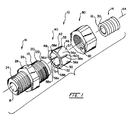
- Fitting 16 which is formed of a generally tubular body, 17, with an axial bore, 18, therethrough, is shown to be of a variety having an externally-threaded forward coupling end, 20, which terminates in a generally forwardly-tapered surface, 22.
- the rearward end, 24, of fitting 16 similarly may be externally-threaded for connection to an auxiliary line of a fuel source, to an appliance or the like (not shown), or to another conduit.
- a pair of fittings 16 may be provided for either end of tubing 14 which may be employed as a transitional fluid conduit between the appliance and the fuel source.
- Body 17 of fitting 16 additionally may be formed as having a radial flange, 26, with hexagonal flats portion, one of which is referenced at 28, configured for engagement with a wrench or other tool during installation or connection.
- Tubing 14 which may be constructed of stainless steel or another metallic material, is conventionally formed of a sinusoidal series of uniform corrugations or convolutions, a first one of which is referenced at 30.
- the convolutions define alternating crest portions which, as is shown at 32, define the outer periphery of tubing 14, and root or trough portions which extend radially inwardly from outer periphery 32.
- Distal end 12 of tubing 14 is formed by sectioning through, preferably centrally, one of the root portions of the tubing to terminate at about or along a first crest portion, 34, having an associated first root portion, 36.
- assembly 10 includes, in accordance with the precepts of the present invention, a coupling which, in turn, includes a generally annular collet member, represented generally at 40, and an associated fastening member, represented generally at 80.
- Fastener 80 may be provided as a hexagonal cap nut which, as is shown at 82, is internally-threaded for a removable engagement with coupling end 20 of fitting 16.
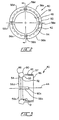
- Collet 40 is formed as having a circumferential wall portion, 42, of a first diameter which is receivable coaxially over distal end 12 of tubing 14.
- Wall portion 42 extends axially along a longitudinal axis, represented at 44, from a forward first end, 46, to a rearward second end 48.
- second end 48 is configured as having a radially outwardly-extending outer portion, 50, and a radially inwardly-extending inner portion, 52, of a second diameter which is smaller than the outer periphery 32 (Fig. 4) of tubing 14.
- Inner portion 52 is configured to be receivable within a root portion of tubing 14 for retaining collet 40 thereon during assembly, and additionally presents a generally rearwardly-facing, ramped compression surface, 54, and a generally forwardly-facing, ramped camming surface, 55.
- camming surface 55 may be radiused to define an angle, referenced at 2, of about 115E with respect to the inner surface of wall portion 42.
- Collet wall portion 42 is longitudinally dissected through second end 48 thereof into at least a pair of arcuate, cantilevered segments, four of which are referenced at 56a-d, which extend from a generally circumferentially-continuous tang portion, 57, of collet 40.
- wall portion 42 is longitudinally dissected into segments 56 by a corresponding number of rebates or slots, 58a-d.
- rebates 58 extends as is shown in Fig. 1 for rebate 58a and in Fig. 3 for rebate 58c through collet second end 48 to terminate at a proximal end, 60a and 60c, respectively, disposed intermediate second end 48 and first end 46 of collet 40.
- rebates 58 may be equally spaced-apart radially about longitudinal axis 44 to dissect collet 40 into at least a pair of equal segments 56.
- the preferred number of segments 56 may vary as generally depending upon the nominal diameter of collet 40, but typically will be between from two and eight.
- each of segments 56 are provided to be resiliently yieldable or pivotable for radial outward movement relative to longitudinal axis 44. It will be appreciated that this movement, which is responsive to the bearing of collet camming surface 55 along the crest portions of the tubing, allows at least first crest portion 34 of tubing 14 to be received through second end 48 of collet wall portion 42 as collet 40 is advanced forwardly over the distal end 12 of tube 14.
- collet 40 advantageously may be provided as a one-piece component which is positively positioned and retained on tubing 14 to facilitate assembly.
- Fastener 80 is journaled over the second end 48 of collet 40 for a threaded engagement with coupling end 20 of fitting 16 (Fig. 1) drawing collet 40 and tubing distal end 12 toward fitting 16.
- fastener 80 may be conventionally formed as extending from an open rearward end, 84, to a forward end, 86, which includes a radially inwardly-projecting flange or collar portion, 88, having an opening, referenced at 90, which is sized to receive collet first end 46 and tubing outer periphery 32 concentrically therethrough.
- collet first end 46 may be flared such that fastener 80 is slidably retained on collet 40 intermediate first and second ends 46 and 48 thereof.
- collet 40 may be staked into fastener 80, or a slot may be provided on an inner surface of the fastener for receiving a corresponding lip or flange of the collet.
- Fastener 80 additionally is formed as having an inner radial surface, 94, a portion of which may define threads 82. From threaded portion 82, radial surface 94 extends to a rearward portion, 96, which is sized radially to accept the outward movement of collet segments 56 as collet 40 is advanced over the distal end 12 of tubing 14. As is shown at 97, it is preferred that collet second end outer portion 50 is generally inclined or angled forwardly to maximize its clearance when pivoted with the inner radial surface 94 of fastener 80. It additionally is preferred that rearward portion 96 of radial surface 94 is configured as a generally circumferentially-continuous annular groove which may have a forwardly-facing shoulder portion, 98.
- the rearward movement of collet 40 relative to tubing 14 may be delimited by shoulder portion 98 and/or collet second end flare 92 as the collet is advanced forwardly over tubing distal end 12 during assembly.
- fastener inner radial surface 94 further extends forwardly to a rearwardly-facing shoulder portion, 100.
- shoulder portion 100 is configured to abuttingly engage outer portion 50 of collet second end 48 when inner portion 52 thereof is received within one of the root portions, such as first root portion 36, of tubing 14.
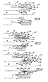
- assembly 10 is illustrated with the internal threads 82 of fastener 80 being engaged with the external threads of coupling end 20 of fitting 16 drawing distal end 12 of tubing 14 into a removable fluid or other connection with fitting throughbore 18.
- fastener open end 84 is rotated onto fitting coupling end 20
- the abutting engagement of collet second end outer portion 50 by fastener shoulder portion 100 urges collet 40 rearwardly toward fitting 16.
- at least the first crest portion 34 of tubing 14 is collapsed and compressed between the tapered surface 22 of fitting 16 and the compression surface 54 of collet 40 in a fluid-tight or other sealing engagement.
- crest portion 34 may be collapsed prior to connection using a flaring tool or the like (not shown).
- collet compression surface 54 is rearwardly inclined or angled for disposition generally parallel to fitting tapered surface 22.
- FIG. 6 an alternative embodiment of coupling assembly 10 of the present invention is shown generally at 10' as including a modified fitting, 16'.
- the forward coupling end 20 of fitting 16' is modified to include a counterbore, referenced at 150, which is formed at the forward opening end of axial bore 18.
- Tapered surface 22 terminates at counterbore 150 to define a generally annular, forwardly-presenting radial land portion, 156, which is sized to confront the first crest portion 34 of tube 14 intermediate the major and minor diametric extents, shown respectively at 152 and 154, of the tube.
- land portion 156 advantageously displaces the contact point between the first crest portion 34 of the tubing and the fitting surface 22 radially outward to effect the flaring compression of the tube distal end intermediate the major and minor diametric extents thereof.
- tube 14 typically is cut to length with a conventional C-clamp type tubing cutter or the like
- the incised or cut end of the tube which may be seen at 158 to extend radially inwardly of the tube minor diameter 154, presents at least the potential for scratching or otherwise damaging surface 22.
- FIG. 8 another alternative embodiment of coupling assembly 10 of the present invention which affords a self-piloting feature is shown generally at 10" as including modified fitting 16".
- the forward coupling end 20 of fitting 16" includes counterbore 150, but is configured without tapered surface 22 or land portion 156. Rather, counterbore 150 is configured to receive at least a portion of the first crest portion 34 therein as having a diameter, referenced at "D” in Fig. 8, which is about 0.0127-0.0635 cm (0.005-0.025 inch) larger than the tube major diameter 152, and as having an axial depth, referenced at "d” in Fig.
- Counterbore 150 further is configured to define as internal, forwardly-presenting surface or step, 160, which extends within the fitting bore 18 radially about axis 44.
- internal step 160 provides a both a positive stop and a sealing surface for the tube distal end 12.
- fastening member 80 and fitting 16" are pre-engaged by partially threading surface 82 of the fastening member onto the first thread of fitting forward coupling end 20.
- a conventional thread locking material such as a Loctite Type 292TM, may be used to temporarily affix the fastening member to the fitting.
- tube distal end 12 may be inserted through the forward end 86 of the fastener until a positive stop with internal step 160 is established disposing collet inner portion 52 within, for example, the third root portion, 162, of the tube. It will be appreciated that the pre-assembling of the coupling automatically effects the desired tube depth insertion. Alternatively, visual inspection may be used to confirm the tube has been inserted the proper amount into the fastening member and fitting.
- the assembly of coupling 10" continues with the compression of the first corrugation 34 and second corrugation, 164, of the tube to effect a fluid-tight sealing thereof to the internal surface 160 of the fitting.
- fastener 80 may be rotated into a further threaded engagement with fitting forward end 20 drawing the tube distal end 12 into a removable fluid or other connection with fitting throughbore 18.
- the first and second crest portion 34 and 164 of the are collapsed and compressed in an "accordion" fluid-tight or other sealing arrangement between fitting internal step 160 and the compression surface 54 of collet 40.
- multiple or redundant sealing surfaces advantageously are provided, such as the radial seal shown at 166 effected between the contact surfaces of the tube and fitting step 160, and the axial seal shown at 168 effected between the apex of tube first crest portion 134 and the inner radial surface, 170, of counterbore 156.
- Materials of construction for tubing 14, fitting 16, collet 40, and fastener 80 are to be considered conventional for the uses involved. Such materials generally will be corrosion resistant, but particularly will depend upon the fluid or fluids being handled. A metal material such as a mild or stainless steel or brass is preferred for durability, although other types of materials such as plastics may be substituted, however, again as selected for compatibility with the fluid being transferred or for desired mechanical properties.
Landscapes
- Engineering & Computer Science (AREA)
- General Engineering & Computer Science (AREA)
- Mechanical Engineering (AREA)
- Quick-Acting Or Multi-Walled Pipe Joints (AREA)
Description
Claims (9)
- A coupling for connecting a distal end (12) of a corrugated tube (14) with a fitting (16) of a variety having a forward coupling end (20), the tube (14) being formed of a series of corrugations (30) which define alternating crest portions (34) defining the outer periphery (32) of the tube (14) and root portions (36), said coupling comprising a generally annular collet member (40) receivable coaxially over the distal end (12) of the tube (14) including a circumferential wall portion (42) extending axially along a longitudinal axis (44) from a forward first end (46) to a rearward second end (48) configured as having a radially-outwardly extending outer portion (50) and a radially inwardly-extending inner portion (52) of a diameter smaller than the outer periphery (32) of the tube (14), said inner portion (52) configured to be receivable within the root portions (36) of the tube (14) for retaining said collet member (40) thereon and presenting a generally rearwardly-facing compression surface (54) and a generally forwardly-facing camming surface (55), and a fastening member (80) journalable over said collet member (40) first end (46) and engagable with the coupling end (20) of the fitting (16) to draw said collet member (40) and the distal end (12) of the tube (14) toward the fitting (16) or the collet (40) is drawn over a preinserted tube distal end (12), said coupling being characterized in that:said wall portion (42) of said collet member (40) is longitudinally dissected through the second end (48) thereof into at least a pair of arcuate, cantilevered segments (56) each being resiliently yieldable responsive to the bearing of said collet camming surface (55) on the crest portions (34) of the tube (14) for radial outward movement relative to said longitudinal axis (44) allowing the crest portions (34) to be received through the second end (48) of said wall portion (42) as said collet member (40) is advanced forwardly over the distal end (12) of the tube (14) into retention within one of the root portions (36); andsaid fastening member (80) has an inner radial surface (94) extending from a rearward portion (96) being sized radially to accept, with fastening member (80) journaled over said collet member (40) first end (46), the outward movement of said collet member (40) segments (56), to a rearwardly-facing shoulder portion (100) configured to abuttingly engage the outer portion (50) of said collet member (40) second end (48) when the inner portion (52) thereof is retained within one of the root portions (36) of the tube (14) for urging said collet member (40) rearwardly toward said fitting (16).
- The coupling as in claim 1 wherein the fitting (16) forward coupling end (20) terminates in a generally forwardly tapered surface (22) and the distal end (12) of the tube (14) terminates at a first corrugation (30), and wherein at least the first corrugation (30) of the tube (14) distal end (12) is collapsed between the tapered surface (22) of the fitting (16) and the compression surface (54) of said collet member (40) as said collet member (40) is drawn toward the fitting (16).
- The coupling as in claim 2 wherein said compression surface (54) of said collet member (40) is presented as a rearwardly-inclined ramped surface disposed generally parallel to the tapered surface (22) of the fitting (16).
- The coupling as in claim 1 wherein said collet member (40) wall portion (42) is longitudinally dissected by at least a pair of rebates (58) each extending through said collet member (40) second end (48) to a proximal end (60) disposed intermediate said collet member (40) first and second ends.
- The coupling as in claim 4 wherein said rebates (58) are equally spaced-apart radially about said longitudinal axis (44) to divide said collet member (40) into at least a pair of equal segments (56).
- The coupling as in claim 1 wherein said collet member (40) is dissected into at least a pair of equal segments (56).
- The coupling as in claim 1 wherein said fastening member (80) is a cap nut configured for a removable threaded engagement with the coupling end (20) of the fitting (16).
- The coupling as in claim 1 wherein the rearward portion (96) of said fastening member (80) inner radial surface (94) is configured as a generally circumferentially-continuous annular groove.
- The coupling as in claim 1 wherein fastening member (80) is slidably retained on said collet member (40) intermediate the first and second ends thereof.
Applications Claiming Priority (3)
| Application Number | Priority Date | Filing Date | Title |
|---|---|---|---|
| US1722796P | 1996-05-09 | 1996-05-09 | |
| PCT/US1997/006707 WO1997042442A1 (en) | 1996-05-09 | 1997-04-24 | Coupling for corrugated tubing |
| US17227P | 2007-12-28 |
Publications (2)
| Publication Number | Publication Date |
|---|---|
| EP0898677A1 EP0898677A1 (en) | 1999-03-03 |
| EP0898677B1 true EP0898677B1 (en) | 2000-06-07 |
Family
ID=21781436
Family Applications (1)
| Application Number | Title | Priority Date | Filing Date |
|---|---|---|---|
| EP97925409A Expired - Lifetime EP0898677B1 (en) | 1996-05-09 | 1997-04-24 | Coupling for corrugated tubing |
Country Status (5)
| Country | Link |
|---|---|
| US (1) | US6019399A (en) |
| EP (1) | EP0898677B1 (en) |
| CA (1) | CA2253827C (en) |
| DE (1) | DE69702254T2 (en) |
| WO (1) | WO1997042442A1 (en) |
Cited By (2)
| Publication number | Priority date | Publication date | Assignee | Title |
|---|---|---|---|---|
| DE202009014913U1 (en) | 2009-12-23 | 2010-03-04 | Berkmann-Krumm, Claudia | Corrugated pipe connector |
| CN104132199A (en) * | 2014-07-04 | 2014-11-05 | 洛阳疋姆泰可精密零件制造有限公司 | Back ferrule for double-ferrule pipe joint |
Families Citing this family (45)
| Publication number | Priority date | Publication date | Assignee | Title |
|---|---|---|---|---|
| US6079749C1 (en) | 1996-08-08 | 2001-11-06 | Omega Flex Inc | Preassembled fitting for use with corrugated tubing |
| FR2764043B1 (en) * | 1997-06-03 | 1999-08-06 | Sevylor International | QUICK COUPLING FOR FLEXIBLE HOSE |
| US6276728B1 (en) | 1999-07-08 | 2001-08-21 | Omega Flex, Inc. | Fitting for use with corrugated tubing |
| US6431610B1 (en) * | 1999-10-14 | 2002-08-13 | Beijing Bork Metal Hose, Co., Ltd. | Tube assembly for communicating water to a fixture |
| DE19957567B4 (en) * | 1999-11-30 | 2004-04-08 | Rasmussen Gmbh | Diffusion-tight fluid line |
| DE10015911B4 (en) * | 2000-03-30 | 2006-06-29 | Zf Sachs Ag | Axial securing of two components with a retaining ring |
| DE10032926A1 (en) * | 2000-07-06 | 2002-01-24 | Hummel Anton Verwaltung | Connection fitting for circumferentially ribbed elongated bodies with a snap-in retaining projection |
| DE50306424D1 (en) * | 2002-03-22 | 2007-03-22 | Witzenmann Gmbh | Connecting device for a ring-corrugated metal hose |
| US6742815B2 (en) | 2002-05-08 | 2004-06-01 | Dormont Manufacturing Company | Fluid line connector assembly |
| US6908114B2 (en) | 2003-02-07 | 2005-06-21 | Parker-Hannifin Corporation | Pre-assemblable, push-in fitting connection for corrugated tubing |
| US6877781B2 (en) * | 2003-07-31 | 2005-04-12 | Highlands Corporation | Corrugated tube fitting |
| CA2459637C (en) * | 2004-02-27 | 2010-04-27 | Masco Canada Limited | Pipe coupling |
| WO2005124217A1 (en) * | 2004-06-18 | 2005-12-29 | Dong-A Flexible Metal Tubes Co., Ltd | Connector of flexible pipe |
| US7055868B2 (en) * | 2004-07-09 | 2006-06-06 | Highlands Corporation | Corrugated tube fitting |
| US8240719B2 (en) * | 2004-07-21 | 2012-08-14 | Parker-Hannifin Corporation | Adaptor and method for converting standard tube fitting/port to push-to-connect tube fitting/port |
| US7914050B2 (en) * | 2004-07-21 | 2011-03-29 | Parker-Hannifin Corporation | Adaptor and method for converting standard tube fitting/port to push-to-connect tube fitting/port |
| EP1659326B1 (en) | 2004-11-17 | 2010-01-06 | Highlands Corporation | Corrugated tube fitting |
| DE102005060576B4 (en) * | 2004-12-21 | 2020-08-20 | Meibes System-Technik Gmbh | Corrugated pipe screw connection / connection connection |
| US7690695B2 (en) * | 2005-07-18 | 2010-04-06 | Titeflex Corporation | Sealing fitting and seal seat for stainless steel tubing |
| US20070284878A1 (en) * | 2005-07-18 | 2007-12-13 | Titeflex Corporation | Sealing fitting for stainless steel tubing |
| US20070013189A1 (en) * | 2005-07-18 | 2007-01-18 | Titeflex Corporation | Sealing fitting for stainless steel tubing |
| WO2007011953A1 (en) * | 2005-07-19 | 2007-01-25 | Mehdi Golafshani | Fitting assembly for deformably sealing corrugated tubing and a method for using the same |
| US7690693B2 (en) * | 2005-08-04 | 2010-04-06 | Parker-Hannifin Corporation | Pre-assemblable, push-in fitting connection for corrugated tubing |
| US20120049509A1 (en) | 2005-08-22 | 2012-03-01 | Lininger Thomas B | Secondary contained csst pipe and fitting assembly |
| US20080012300A1 (en) * | 2005-10-12 | 2008-01-17 | Titeflex Corporation | Iron fitting for stainless steel tubing |
| US20070103263A1 (en) * | 2005-11-07 | 2007-05-10 | Gutierrez Orlando E | Snap ring for holding solenoid in housing |
| US7621567B2 (en) * | 2006-05-24 | 2009-11-24 | Titeflex Corporation | Corrugated tube fitting with a ridge sealing device and method |
| DE202007010592U1 (en) | 2007-07-27 | 2008-12-11 | Az Pokorny S.R.O. | Arrangement for fastening a line with a profiled outside diameter |
| TWI432664B (en) * | 2007-09-10 | 2014-04-01 | 奧米茄菲利斯股份有限公司 | Connector for piping containment system |
| ES2395153T3 (en) * | 2008-01-22 | 2013-02-08 | Serto Holding Ag | Pipe fitting for corrugated metal pipes |
| ES2400384T3 (en) | 2009-07-17 | 2013-04-09 | Beulco Gmbh & Co. Kg | Corrugated pipe fitting |
| DE202009005038U1 (en) | 2009-07-17 | 2010-12-30 | Gebrüder Beul GmbH & Co KG | Wellrohranschlussverschraubung |
| DE202009015214U1 (en) * | 2009-11-10 | 2010-02-18 | LTL Leitungstechnische Lösungen GmbH | Wellrohrkompensator |
| US8925976B2 (en) * | 2010-03-02 | 2015-01-06 | Omega Flex, Inc. | Flanged fitting for use with tubing containment system |
| US8226128B2 (en) * | 2010-08-11 | 2012-07-24 | Ming-Yi Lee | Releasable nut-free C-clip secured pipe fitting |
| US8746750B2 (en) * | 2011-02-08 | 2014-06-10 | The Gates Corporation | Variable curvature clip for quick connect coupling |
| ITBS20110083A1 (en) * | 2011-06-07 | 2012-12-08 | M F C S R L | FITTING |
| US9140392B2 (en) * | 2013-04-11 | 2015-09-22 | Omega Flex, Inc. | Fitting for tubing containment system |
| CN104633351B (en) * | 2014-12-15 | 2017-02-22 | 中航光电科技股份有限公司 | Connector |
| US10281071B2 (en) | 2015-12-02 | 2019-05-07 | Titeflex Corporation | Bushings and fittings, tubing assemblies, and methods incorporating the same |
| JP6717647B2 (en) * | 2016-04-18 | 2020-07-01 | 日立オートモティブシステムズ株式会社 | Propeller shaft |
| JP6717688B2 (en) * | 2016-06-30 | 2020-07-01 | 日立オートモティブシステムズ株式会社 | Propeller shaft |
| MY191096A (en) * | 2018-02-14 | 2022-05-30 | Norma China Co Ltd | Compression fitting with a securing means |
| GB2626563A (en) * | 2023-01-26 | 2024-07-31 | FlexiGas UKC Ltd | Adapter sleeve, kit comprising the same, and method of adapting a conventional compression fitting for use with a length of corrugated tubing |
| USD1089563S1 (en) | 2024-09-24 | 2025-08-19 | Jason Anthony Steuber | Garden hose fitting adapter |
Family Cites Families (60)
| Publication number | Priority date | Publication date | Assignee | Title |
|---|---|---|---|---|
| US178313A (en) * | 1876-06-06 | Improvement in pipe-couplings | ||
| US262581A (en) * | 1882-08-15 | doolittle | ||
| US546314A (en) * | 1895-09-17 | Pipe-coupling | ||
| US96914A (en) * | 1869-11-16 | Improvement in pipe-coupling | ||
| US2112238A (en) * | 1936-03-07 | 1938-03-29 | Packless Metal Products Corp | Flexible tube coupling |
| US2113211A (en) * | 1937-03-18 | 1938-04-05 | Philip L Lake | Renewable fitting for parallel corrugated flexible hose |
| US2323912A (en) * | 1940-04-30 | 1943-07-13 | Chicago Metal Hose Corp | Coupling construction |
| US2363586A (en) * | 1943-04-17 | 1944-11-28 | Packless Metal Products Corp | Flexible tube coupling |
| US2430657A (en) * | 1943-05-06 | 1947-11-11 | John G Zolleis | Coupling |
| US2357669A (en) * | 1943-06-26 | 1944-09-05 | Philip L Lake | Removable fitting for corrugated flexible hose |
| US2424727A (en) * | 1944-04-21 | 1947-07-29 | Keystone Mfg Co | Adapter for flared tube fittings |
| GB588902A (en) * | 1945-03-09 | 1947-06-05 | Tube Patents Ltd | Improvements in or relating to a method of and means for coupling together pipes, tubular bodies and the like |
| US2496149A (en) * | 1946-07-26 | 1950-01-31 | Harry Alter Company | Coupler |
| US2497273A (en) * | 1946-08-21 | 1950-02-14 | Brockway Company | Pipe connection |
| US2549741A (en) * | 1946-11-28 | 1951-04-17 | Thomas R Young | Pipe joint |
| US2848254A (en) * | 1950-05-01 | 1958-08-19 | Millar John Humphrey | End fittings for flexible metallic hose |
| US2858147A (en) * | 1954-04-21 | 1958-10-28 | Titeflex Inc | Renewable fitting for reinforced metallic hose |
| US2946607A (en) * | 1956-12-06 | 1960-07-26 | Matthew F Bauer | Self-flaring tube coupling |
| US3008736A (en) * | 1957-01-30 | 1961-11-14 | Samiran David | High pressure flexible hose coupling |
| US2991093A (en) * | 1959-02-25 | 1961-07-04 | Titeflex Inc | Hose with self gasketing feature |
| US3112937A (en) * | 1960-12-19 | 1963-12-03 | Stratoflex Inc | Hose fitting having connecting means for an internal reinforcing member and method of assembly |
| US3214200A (en) * | 1963-09-05 | 1965-10-26 | Varian Associates | Tube coupling having deforming means |
| US3306637A (en) * | 1964-09-04 | 1967-02-28 | Resistoflex Corp | Reuseable hose end fitting |
| US3381980A (en) * | 1964-09-08 | 1968-05-07 | Olin Mathieson | Pipe joint |
| US3294426A (en) * | 1965-04-19 | 1966-12-27 | L & L Mfg Company | Self-flaring tube coupling |
| FR1508220A (en) * | 1966-11-21 | 1968-01-05 | Moulages Ind Plasto | Quick coupling for flexible hoses |
| GB1371609A (en) * | 1970-12-05 | 1974-10-23 | Markes Co Ltd | Pipe joint |
| US3888522A (en) * | 1974-04-01 | 1975-06-10 | Weatherhead Co | Flareless fitting |
| US4136897A (en) * | 1976-04-08 | 1979-01-30 | Parker-Hannifin Corporation | Coupling device for tubular members |
| DE2627397C3 (en) * | 1976-06-18 | 1980-09-11 | Ermeto Armaturen Gmbh, 4800 Bielefeld | Quick coupling for connecting pipe or hose lines |
| US4046451A (en) * | 1976-07-08 | 1977-09-06 | Andrew Corporation | Connector for coaxial cable with annularly corrugated outer conductor |
| US4423891A (en) * | 1981-09-28 | 1984-01-03 | Menges William H | Corrugated hose coupling |
| JPS6073193A (en) * | 1983-09-30 | 1985-04-25 | 日立金属株式会社 | Pipe joint |
| US4669761A (en) * | 1984-07-19 | 1987-06-02 | Marshall Brass Company | Tubing fitting |
| DE3508198C2 (en) * | 1985-03-08 | 1987-01-08 | Martin 7050 Waiblingen Biermann | Device for detachable connection of a cable |
| JPS6220292U (en) * | 1985-07-22 | 1987-02-06 | ||
| FR2589979B3 (en) * | 1985-11-14 | 1988-08-05 | Bizet Sa Ets Guy | REUSABLE CONNECTION DEVICE FOR PARALLEL WAVE PIPES |
| US4867489A (en) * | 1987-09-21 | 1989-09-19 | Parker Hannifin Corporation | Tube fitting |
| JPH0342302Y2 (en) * | 1987-11-10 | 1991-09-04 | ||
| JPH0339674Y2 (en) * | 1987-11-10 | 1991-08-21 | ||
| US4836580A (en) * | 1988-03-01 | 1989-06-06 | Scepter Manufacturing Company Limited | Conduit connector |
| US4909547A (en) * | 1988-05-26 | 1990-03-20 | Chardon Rubber Company | Coupler arrangement |
| US4872710A (en) * | 1988-10-07 | 1989-10-10 | Stratoflex, Inc. | Releasable quick connect fitting |
| FR2642500B1 (en) * | 1989-01-30 | 1991-04-19 | Parker Hannifin Rak Sa | PROCESS FOR PRODUCING A SEALED CONNECTION FOR A RIGID TUBE AND CONNECTION THEREOF |
| SU1742571A1 (en) * | 1990-06-28 | 1992-06-23 | Головное Специализированное Конструкторско-Технологическое Бюро Сельхозхиммаш | Device for connecting corrugated hose lines |
| US5080405A (en) * | 1990-07-10 | 1992-01-14 | Nitto Kohki Co., Ltd. | Corrugated pipe coupling |
| JP2986522B2 (en) * | 1990-09-14 | 1999-12-06 | 光陽産業株式会社 | Flexible pipe fittings |
| IT1250869B (en) * | 1991-12-06 | 1995-04-21 | Rachetto S P A | RAPID SEALING CONNECTION DEVICE, FOR NON BRAIDED METAL HOSES. |
| JPH0776595B2 (en) * | 1992-06-25 | 1995-08-16 | 工業技術院長 | Pipe fitting for double pipe |
| US5226682A (en) * | 1992-07-21 | 1993-07-13 | Aeroquip Corporation | Coupling assembly |
| US5292156A (en) * | 1992-09-11 | 1994-03-08 | Nitto Kohki Co., Ltd. | Corrugated pipe coupling |
| DE4334529C2 (en) * | 1992-10-15 | 1996-06-13 | Furukawa Electric Co Ltd | Connection device for a flexible corrugated pipe |
| US5261707A (en) * | 1992-12-07 | 1993-11-16 | Nitto Kohki Co., Ltd. | Joint for connection of a corrugated pipe |
| US5423578A (en) * | 1993-03-08 | 1995-06-13 | Tokyo Gas Co., Ltd. | Coupling for corrugated pipe |
| US5413147A (en) * | 1993-04-29 | 1995-05-09 | Parker-Hannifin Corporation | Flexible hose and fitting assembly |
| US5489127A (en) * | 1993-08-25 | 1996-02-06 | Itt Corporation | Mounting apparatus with reduced resistance bead seal |
| JPH07145894A (en) * | 1993-10-01 | 1995-06-06 | Tokyo Gas Co Ltd | Flexible pipe fittings |
| US5580105A (en) * | 1995-01-12 | 1996-12-03 | Midtec, Inc. Of America | Locking arrangement for a plumbing connection |
| US5543582A (en) * | 1995-05-23 | 1996-08-06 | Stark; Thomas S. | Liquid tight cord grip |
| US5799989A (en) * | 1996-08-08 | 1998-09-01 | Omega-Flex, Inc. | Corrugated tubing fitting |
-
1997
- 1997-04-24 CA CA002253827A patent/CA2253827C/en not_active Expired - Fee Related
- 1997-04-24 DE DE69702254T patent/DE69702254T2/en not_active Expired - Lifetime
- 1997-04-24 EP EP97925409A patent/EP0898677B1/en not_active Expired - Lifetime
- 1997-04-24 WO PCT/US1997/006707 patent/WO1997042442A1/en not_active Ceased
- 1997-12-13 US US08/990,206 patent/US6019399A/en not_active Expired - Fee Related
Cited By (2)
| Publication number | Priority date | Publication date | Assignee | Title |
|---|---|---|---|---|
| DE202009014913U1 (en) | 2009-12-23 | 2010-03-04 | Berkmann-Krumm, Claudia | Corrugated pipe connector |
| CN104132199A (en) * | 2014-07-04 | 2014-11-05 | 洛阳疋姆泰可精密零件制造有限公司 | Back ferrule for double-ferrule pipe joint |
Also Published As
| Publication number | Publication date |
|---|---|
| EP0898677A1 (en) | 1999-03-03 |
| CA2253827A1 (en) | 1997-11-13 |
| WO1997042442A1 (en) | 1997-11-13 |
| CA2253827C (en) | 2006-05-23 |
| DE69702254T2 (en) | 2000-10-12 |
| DE69702254D1 (en) | 2000-07-13 |
| US6019399A (en) | 2000-02-01 |
Similar Documents
| Publication | Publication Date | Title |
|---|---|---|
| EP0898677B1 (en) | Coupling for corrugated tubing | |
| US6036237A (en) | Coupling for corrugated tubing | |
| CA2514923C (en) | Push-in fitting for corrugated tubing | |
| US7690693B2 (en) | Pre-assemblable, push-in fitting connection for corrugated tubing | |
| US7469936B2 (en) | Pipe coupling | |
| US20120049509A1 (en) | Secondary contained csst pipe and fitting assembly | |
| US3815940A (en) | Joint for smooth end or flareless pipe | |
| WO1992000485A1 (en) | A pipe coupling | |
| US9175794B2 (en) | Device for connecting male and female piping | |
| US20100171302A1 (en) | Push-twist connector | |
| US9371945B2 (en) | Corrugated tube connector | |
| JPH07269749A (en) | Pipe joint device | |
| CA2571280A1 (en) | Reusable fitting for tubing | |
| CN110869659A (en) | Pipes, especially plastic pipes for waste water lines | |
| US4786089A (en) | Automatically locking tubing coupler | |
| DK2542812T3 (en) | Flange fitting for a pipe containment system | |
| AU2019100400C4 (en) | Plumbing Fitting | |
| CN216643433U (en) | Pipe joint without O-shaped ring | |
| JP2007255685A (en) | Pipe joint | |
| GB2274696A (en) | Swivel type hose end fitting | |
| US20060163872A1 (en) | Pipe coupling | |
| AU666153B2 (en) | Swivel type hose end fitting | |
| MX2008001052A (en) | Pre-assemblable, push-in fitting connection for corrugated tubing | |
| MXPA06015053A (en) | Reusable fitting for tubing | |
| MXPA98002750A (en) | Corrugated tubing fitting |
Legal Events
| Date | Code | Title | Description |
|---|---|---|---|
| PUAI | Public reference made under article 153(3) epc to a published international application that has entered the european phase |
Free format text: ORIGINAL CODE: 0009012 |
|
| 17P | Request for examination filed |
Effective date: 19981012 |
|
| AK | Designated contracting states |
Kind code of ref document: A1 Designated state(s): DE FR GB NL |
|
| GRAG | Despatch of communication of intention to grant |
Free format text: ORIGINAL CODE: EPIDOS AGRA |
|
| 17Q | First examination report despatched |
Effective date: 19990510 |
|
| GRAG | Despatch of communication of intention to grant |
Free format text: ORIGINAL CODE: EPIDOS AGRA |
|
| GRAG | Despatch of communication of intention to grant |
Free format text: ORIGINAL CODE: EPIDOS AGRA |
|
| GRAH | Despatch of communication of intention to grant a patent |
Free format text: ORIGINAL CODE: EPIDOS IGRA |
|
| GRAG | Despatch of communication of intention to grant |
Free format text: ORIGINAL CODE: EPIDOS AGRA |
|
| GRAH | Despatch of communication of intention to grant a patent |
Free format text: ORIGINAL CODE: EPIDOS IGRA |
|
| GRAH | Despatch of communication of intention to grant a patent |
Free format text: ORIGINAL CODE: EPIDOS IGRA |
|
| GRAA | (expected) grant |
Free format text: ORIGINAL CODE: 0009210 |
|
| AK | Designated contracting states |
Kind code of ref document: B1 Designated state(s): DE FR GB NL |
|
| REF | Corresponds to: |
Ref document number: 69702254 Country of ref document: DE Date of ref document: 20000713 |
|
| ET | Fr: translation filed | ||
| PLBE | No opposition filed within time limit |
Free format text: ORIGINAL CODE: 0009261 |
|
| STAA | Information on the status of an ep patent application or granted ep patent |
Free format text: STATUS: NO OPPOSITION FILED WITHIN TIME LIMIT |
|
| 26N | No opposition filed | ||
| REG | Reference to a national code |
Ref country code: GB Ref legal event code: IF02 |
|
| PGFP | Annual fee paid to national office [announced via postgrant information from national office to epo] |
Ref country code: FR Payment date: 20110510 Year of fee payment: 15 Ref country code: DE Payment date: 20110421 Year of fee payment: 15 |
|
| PGFP | Annual fee paid to national office [announced via postgrant information from national office to epo] |
Ref country code: NL Payment date: 20110426 Year of fee payment: 15 Ref country code: GB Payment date: 20110421 Year of fee payment: 15 |
|
| REG | Reference to a national code |
Ref country code: NL Ref legal event code: V1 Effective date: 20121101 |
|
| GBPC | Gb: european patent ceased through non-payment of renewal fee |
Effective date: 20120424 |
|
| REG | Reference to a national code |
Ref country code: FR Ref legal event code: ST Effective date: 20121228 |
|
| PG25 | Lapsed in a contracting state [announced via postgrant information from national office to epo] |
Ref country code: GB Free format text: LAPSE BECAUSE OF NON-PAYMENT OF DUE FEES Effective date: 20120424 |
|
| REG | Reference to a national code |
Ref country code: DE Ref legal event code: R119 Ref document number: 69702254 Country of ref document: DE Effective date: 20121101 |
|
| PG25 | Lapsed in a contracting state [announced via postgrant information from national office to epo] |
Ref country code: FR Free format text: LAPSE BECAUSE OF NON-PAYMENT OF DUE FEES Effective date: 20120430 |
|
| PG25 | Lapsed in a contracting state [announced via postgrant information from national office to epo] |
Ref country code: NL Free format text: LAPSE BECAUSE OF NON-PAYMENT OF DUE FEES Effective date: 20121101 |
|
| PG25 | Lapsed in a contracting state [announced via postgrant information from national office to epo] |
Ref country code: DE Free format text: LAPSE BECAUSE OF NON-PAYMENT OF DUE FEES Effective date: 20121101 |