EP0898381B1 - Equalizing method and equalizer for ofdm receiver - Google Patents
Equalizing method and equalizer for ofdm receiver Download PDFInfo
- Publication number
- EP0898381B1 EP0898381B1 EP98306336A EP98306336A EP0898381B1 EP 0898381 B1 EP0898381 B1 EP 0898381B1 EP 98306336 A EP98306336 A EP 98306336A EP 98306336 A EP98306336 A EP 98306336A EP 0898381 B1 EP0898381 B1 EP 0898381B1
- Authority
- EP
- European Patent Office
- Prior art keywords
- predetermined number
- channel
- scattered pilot
- channel characteristic
- scattered
- Prior art date
- Legal status (The legal status is an assumption and is not a legal conclusion. Google has not performed a legal analysis and makes no representation as to the accuracy of the status listed.)
- Expired - Lifetime
Links
Images
Classifications
-
- H—ELECTRICITY
- H04—ELECTRIC COMMUNICATION TECHNIQUE
- H04L—TRANSMISSION OF DIGITAL INFORMATION, e.g. TELEGRAPHIC COMMUNICATION
- H04L5/00—Arrangements affording multiple use of the transmission path
- H04L5/003—Arrangements for allocating sub-channels of the transmission path
- H04L5/0048—Allocation of pilot signals, i.e. of signals known to the receiver
-
- H—ELECTRICITY
- H04—ELECTRIC COMMUNICATION TECHNIQUE
- H04B—TRANSMISSION
- H04B1/00—Details of transmission systems, not covered by a single one of groups H04B3/00 - H04B13/00; Details of transmission systems not characterised by the medium used for transmission
- H04B1/06—Receivers
- H04B1/10—Means associated with receiver for limiting or suppressing noise or interference
-
- H—ELECTRICITY
- H04—ELECTRIC COMMUNICATION TECHNIQUE
- H04B—TRANSMISSION
- H04B7/00—Radio transmission systems, i.e. using radiation field
- H04B7/01—Reducing phase shift
-
- H—ELECTRICITY
- H04—ELECTRIC COMMUNICATION TECHNIQUE
- H04L—TRANSMISSION OF DIGITAL INFORMATION, e.g. TELEGRAPHIC COMMUNICATION
- H04L25/00—Baseband systems
- H04L25/02—Details ; arrangements for supplying electrical power along data transmission lines
- H04L25/0202—Channel estimation
- H04L25/0224—Channel estimation using sounding signals
- H04L25/0226—Channel estimation using sounding signals sounding signals per se
-
- H—ELECTRICITY
- H04—ELECTRIC COMMUNICATION TECHNIQUE
- H04L—TRANSMISSION OF DIGITAL INFORMATION, e.g. TELEGRAPHIC COMMUNICATION
- H04L25/00—Baseband systems
- H04L25/02—Details ; arrangements for supplying electrical power along data transmission lines
- H04L25/0202—Channel estimation
- H04L25/0224—Channel estimation using sounding signals
- H04L25/0228—Channel estimation using sounding signals with direct estimation from sounding signals
- H04L25/023—Channel estimation using sounding signals with direct estimation from sounding signals with extension to other symbols
- H04L25/0232—Channel estimation using sounding signals with direct estimation from sounding signals with extension to other symbols by interpolation between sounding signals
-
- H—ELECTRICITY
- H04—ELECTRIC COMMUNICATION TECHNIQUE
- H04L—TRANSMISSION OF DIGITAL INFORMATION, e.g. TELEGRAPHIC COMMUNICATION
- H04L25/00—Baseband systems
- H04L25/02—Details ; arrangements for supplying electrical power along data transmission lines
- H04L25/03—Shaping networks in transmitter or receiver, e.g. adaptive shaping networks
- H04L25/03006—Arrangements for removing intersymbol interference
- H04L25/03159—Arrangements for removing intersymbol interference operating in the frequency domain
-
- H—ELECTRICITY
- H04—ELECTRIC COMMUNICATION TECHNIQUE
- H04L—TRANSMISSION OF DIGITAL INFORMATION, e.g. TELEGRAPHIC COMMUNICATION
- H04L25/00—Baseband systems
- H04L25/02—Details ; arrangements for supplying electrical power along data transmission lines
- H04L25/03—Shaping networks in transmitter or receiver, e.g. adaptive shaping networks
- H04L25/03006—Arrangements for removing intersymbol interference
- H04L2025/0335—Arrangements for removing intersymbol interference characterised by the type of transmission
- H04L2025/03375—Passband transmission
- H04L2025/03414—Multicarrier
-
- H—ELECTRICITY
- H04—ELECTRIC COMMUNICATION TECHNIQUE
- H04L—TRANSMISSION OF DIGITAL INFORMATION, e.g. TELEGRAPHIC COMMUNICATION
- H04L25/00—Baseband systems
- H04L25/02—Details ; arrangements for supplying electrical power along data transmission lines
- H04L25/03—Shaping networks in transmitter or receiver, e.g. adaptive shaping networks
- H04L25/03006—Arrangements for removing intersymbol interference
- H04L2025/03433—Arrangements for removing intersymbol interference characterised by equaliser structure
- H04L2025/03439—Fixed structures
- H04L2025/03522—Frequency domain
-
- H—ELECTRICITY
- H04—ELECTRIC COMMUNICATION TECHNIQUE
- H04L—TRANSMISSION OF DIGITAL INFORMATION, e.g. TELEGRAPHIC COMMUNICATION
- H04L5/00—Arrangements affording multiple use of the transmission path
- H04L5/0001—Arrangements for dividing the transmission path
- H04L5/0003—Two-dimensional division
- H04L5/0005—Time-frequency
- H04L5/0007—Time-frequency the frequencies being orthogonal, e.g. OFDM(A) or DMT
Definitions
- the present invention relates in general to an equalizer and to an equalizing method for compensating for channel distortion in a receiver for receiving a signal transmitted by an orthogonal frequency division multiplexing (OFDM) method.
- OFDM orthogonal frequency division multiplexing
- OFDM is a type of multiple carrier modulating method for transmitting a digital signal.
- data is carried by a plurality of sub-carriers and transmitted in parallel during a long symbol period, using a frequency band of the same width as that used for transmitting single carrier data. Since a symbol is determined in a frequency domain in the OFDM method, an equalizer used in the frequency domain is required for compensating for channel distortion of the received symbol.
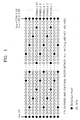
- scattered pilots are transmitted in the OFDM method. However, the scattered pilots are not transmitted through fixed sub channels, but are transmitted through different sub channels in every symbol, having a predetermined pattern, as shown in Figure 1.
- the scattered pilots are repeated using four symbols as one period. Since the scattered pilots are transmitted through the first and final sub channels in a 12 sub channel period, making a second starting point of every symbol different, the characteristics of all the sub channels are estimated by finding out positions to which the scattered pilots are transmitted, calculating estimated values according to all the characteristics of the sub channel, and obtaining the characteristics of the data sub channels between the scattered pilots by interpolating the estimated values of adjacent pilots.
- the distance between the scattered pilots becomes 11 sub channels, a compensation error becomes larger when frequency distortion is generated.
- a precise filter is required as an interpolating filter since there are 11 sub channels between the scattered pilots.
- the document FR 2,743,967 describes a quincunxial arrangement of the scattered pilots, of which a fictions pilot symbol is obtained by grouping together each of the extracted scattered pilots which belong to the quincunxial arrangement.
- an equalizing method for compensating for channel distortion in a plurality of carriers transmitted through a plurality of sub channels using scattered pilots having a period of a first predetermined number of symbols comprising the steps of (a) extracting scattered pilots from a plurality of received carriers and estimating a channel characteristic value in the position of an extracted scattered pilot (b) providing a channel characteristic value in a scattered pilot position having a period of a third predetermined number of sub channels by updating the channel characteristic value of the scattered pilot position of a period having a second predetermined number of sub channels in every symbol, and by maintaining a previous channel characteristic value in the remaining scattered pilots, (c) providing the characteristic values of all the sub channels by estimating the characteristics of a sub channel through which data between scattered pilots is transmitted using the channel characteristic values in the scattered pilot position having the period of the third predetermined number of sub channels, and (d) compensating for the channel distortion of the received plurality of carriers on the basis of all the sub channel characteristic values.
- an equalizer for an OFDM receiver for receiving a plurality of carriers including a scattered pilot having a period of a first predetermined number of symbols through a plurality of sub channels, comprising:
- STEP 1 a channel characteristic value in the position of an extracted scattered pilot is estimated by revealing which symbol is received among four symbols and extracting the scattered pilot from the received symbol.
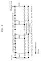
- STEP 2 a channel characteristic value in the position of the scattered pilot having a three sub channel period as shown in Figure 2 is obtained by updating the sub channel through which the scattered pilot is transferred in every symbol into a new value and maintaining the updated value over the next three symbol interval.
- an upper first symbol shows channel characteristics in the position of scattered pilots having a three sub channel period applied to the symbols starting from a received fifth symbol.
- the sub channel through which the scattered pilot is transmitted in every symbol is updated to a new value. Over the next three symbol intervals, the updated value is maintained.
- the sub channel through which each scattered pilot is transmitted is used for transferring the scattered pilot once every four symbols, when the characteristic of the sub channel through which the scattered pilot is transferred in every symbol is updated to a new value and the value is maintained over four symbols, it is possible to adapt to the change of time of the channel.
- STEP 3 the characteristics of two sub channels through which data between two adjacent scattered pilots are transmitted is estimated by interpolating the channel characteristic value of the position of the scattered pilot estimated in STEP 2.
- the characteristics of three sub channels are calculated in the same manner, considering that the characteristic of a sub channel through which the scattered pilot is transmitted is the same as that of the sub channel through which the following two data are transmitted when the characteristics of the sub channel hardly changes.
- the characteristics of the two sub channels through which data are transmitted are calculated by a linear interpolation.
- a windowed finite impulse response (FIR) filter having a higher interpolation performance is used.
- the structure of the equalizer is simple when constant interpolation or linear interpolation are used.
- the accuracy is lower than in the interpolating method according to the windowed FIR filter.
- the interpolating method by the windowed FIR filter is used, the accuracy becomes higher.
- an error may be generated in the starting portion of the symbol since the position of the scattered pilot is continuous at the end and the start of the symbol. Therefore, the constant interpolation or the linear interpolation is used at the starting portion of the symbol.
- the interpolation by the windowed FIR filter is used in the other portions. Accordingly, equalizing performance is improved.
- STEP 4 to estimate the characteristics of the sub channels through which data are transmitted means that the characteristics of all the sub channels are known. Therefore, the amplitude and phase distortion, i.e., the channel distortion, is compensated for by multiplying the transmitted sub channel data by the inverse of the characteristic of the sub channel.
- the sub channel through which a pilot is transmitted can be represented as the following equation 2.
- the amplitude characteristics and the phase characteristics of the sub channel can be obtained from the equation 3.
- R k f H k f ⁇ P k f wherein, P(f) represents a scattered pilot.
- H k f R k f P k f
- the number of sub channels obtained from the scattered pilots of a modified distribution shown in Figure 2 is 6816/3.
- the characteristics of the 6816x2/3 data channel are obtained by an interpolation using the characteristics of the sub channels.
- the constant interpolation or the linear interpolation is performed to every starting portion twelve carriers and an interpolation by a windowed FIR filter is performed to the other portions.
- the windowed FIR filter uses a low pass filter whose sampling frequency is three times a carrier frequency.
- the equalized output represented in the equation 8 is obtained by obtaining the characteristics of all the sub channels by the above method and multiplying the received data by the inverse of the characteristic of the sub channel.
- the windowed FIR filter can be used in order to enhance the interpolation performance.
- the equalization in the frequency domain can be performed by multiplying the received signal by the inverse of the channel characteristics value.
- the equalization becomes very simple since it has the structure of an equalizer having a one tap filter.
- a guard interval remover 102 removes a cyclic prefix (CP) corresponding to a guard interval from the received data.
- a guard band remover 104 performs a fast Fourier transform (FFT) on data output from the guard interval remover 102 and removes the guard band included in the fast Fourier transformed data in units of one symbol in order to convert the data into the data of a frequency domain since the data output from the guard interval remover 102 is data of a time domain.
- FFT fast Fourier transform
- each symbol is formed of 6817 carriers.
- the symbols are transmitted for a duration Ts.
- the duration Ts includes an effective symbol part interval for transmitting the 6817 carriers and a guard interval.
- a scattered pilot extractor 106 extracts the scattered pilot from data output from the guard band remover 104, namely, the 6817 carriers in every symbol in the case of an 8K mode. Since the scattered pilots have a boosted power level, the scattered pilot extractor 106 examines a correlation between the data from which the guard band has been removed and a reference sequence, and extracts the scattered pilot. Since the reference sequence is one symbol pattern data among four symbols, it is possible to find out which is the symbol received at present among the four symbols. Since the scattered pilot is repeated over a four symbol period, the position of the scattered pilot of the four symbols is automatically revealed by revealing the position of the scattered pilot of one symbol. Therefore, it is possible to correctly reveal the position of the scattered pilot of one symbol using the reference sequence by the scattered pilot extractor 106. With respect to the next three symbols, the received level value is output in the already revealed position of the scattered pilot.
- the boosted power level of the received scattered pilot is (4/3) 2 .
- the scattered pilot according to the positions of the respective scattered pilots of the four symbol period during transmission has a coordinate value of (4/3,0) or (-4/3,0). Since this coordinate value, i.e., phase information, is already revealed by a scattered pilot determiner 108, the coordinate value of the scattered pilot extracted from the scattered pilot extractor 106 is output to a channel estimator 110.
- the channel estimator 110 outputs the channel characteristic value in the position of the scattered pilot by channel estimating using a coordinate value according to the position of the scattered pilot output from the scattered pilot determiner 108. Namely, the channel estimator 110 compares the boosted level of the scattered pilot extracted by the scattered pilot extractor 106 with the original coordinate value and outputs a value (r) for compensating for the amplitude distortion and a value ( ⁇ ) for compensating for the phase distortion.
- a channel characteristic updater 112 updates the channel characteristic value of the sub channel through which each scattered pilot is transmitted into a new value in every symbol and maintains the updated value during the next three symbols. By doing so, an equalizing coefficient is updated into a new value in the scattered pilot position of the 12 sub channel distance in every symbol. The equalizing coefficients in the remaining scattered pilot positions maintain their previous values.
- the distance between the sub channels through which the scattered pilots are transmitted is two sub channels. However, the current channel characteristics of the scattered pilot are reflected by 1/4 (12 sub channel distance) in every symbol. Accordingly, it is possible to adapt to the characteristics of the channel changing as time goes by.
- a coefficient interpolator 114 performs linear interpolation, constant interpolation or windowed FIR filter interpolation on the basis of the channel characteristic value in the pilot position of the three sub channel period in which the channel characteristics of the scattered pilots are updated by a distance of 12 sub channels in every symbol provided from the channel characteristic updater 112, and outputs the interpolated coefficients in order to estimate the sub channel characteristics of the data of the two sub channels between pilots.
- a frequency domain equalizer 116 can be constructed of a filter having one tap, namely, a multiplier.
- the frequency domain equalizer 116 outputs data compensated by multiplying the data output from the guard band remover 104 by the inverse of the coefficient interpolated by the coefficient interpolator 114.
- Figure 4 is a block diagram of the coefficient interpolator 114 shown in Figure 3.
- a modulo counter 120 modulo counts the output of the channel characteristic updater 112 shown in Figure 3 according to a symbol synchronizing signal from 0 to 6816 since one symbol is comprised of 6817 effective carriers and generates a select control signal when numbers to a predetermined number (here, 11) in the starting portion of every symbol are counted.
- a divider 122 constituted of a demultiplexer outputs to a constant interpolator 124 the channel characteristic values in the starting portion of every symbol among the channel characteristic values in the scattered pilot position output from the channel characteristic updater 112 according to the select control signal output from the modulo counter 120, and outputs the remaining channel characteristic values to a windowed FIR filter 126.
- the constant interpolator 124 can be replaced by a linear interpolator.
- the windowed FIR filter 126 is constituted of a low pass filter whose sampling frequency is three times the carrier frequency.
- a selector 128 constituted of a multiplexer selects the output of the constant interpolator 124 in the case of the starting portion of a symbol according to the select control signal generated by the modulo counter 120, otherwise selects the windowed FIR filter 126, and outputs the selected signal to the frequency domain equalizer 116 shown in Figure 3.
- Figure 4 shows the divider 122 and the selector 128. However, the divider 122 may be omitted.
- the amount of calculating is reduced by reducing the distance between scattered pilots, adapting to the channel changing as time goes by.
- the structure of the interpolator employed in the equalizer described above is simple, since only the characteristics of two data sub channels are interpolated. It is possible to improve the performance of the equalizer by operating two types of interpolators.
Landscapes
- Engineering & Computer Science (AREA)
- Signal Processing (AREA)
- Computer Networks & Wireless Communication (AREA)
- Power Engineering (AREA)
- Cable Transmission Systems, Equalization Of Radio And Reduction Of Echo (AREA)
- Digital Transmission Methods That Use Modulated Carrier Waves (AREA)
Description
- The present invention relates in general to an equalizer and to an equalizing method for compensating for channel distortion in a receiver for receiving a signal transmitted by an orthogonal frequency division multiplexing (OFDM) method.
- OFDM is a type of multiple carrier modulating method for transmitting a digital signal. In the OFDM method, data is carried by a plurality of sub-carriers and transmitted in parallel during a long symbol period, using a frequency band of the same width as that used for transmitting single carrier data. Since a symbol is determined in a frequency domain in the OFDM method, an equalizer used in the frequency domain is required for compensating for channel distortion of the received symbol. For this, scattered pilots are transmitted in the OFDM method. However, the scattered pilots are not transmitted through fixed sub channels, but are transmitted through different sub channels in every symbol, having a predetermined pattern, as shown in Figure 1.
- Namely, as shown in Figure 1, the scattered pilots are repeated using four symbols as one period. Since the scattered pilots are transmitted through the first and final sub channels in a 12 sub channel period, making a second starting point of every symbol different, the characteristics of all the sub channels are estimated by finding out positions to which the scattered pilots are transmitted, calculating estimated values according to all the characteristics of the sub channel, and obtaining the characteristics of the data sub channels between the scattered pilots by interpolating the estimated values of adjacent pilots. However, in the case of performing interpolating in every symbol, since the distance between the scattered pilots becomes 11 sub channels, a compensation error becomes larger when frequency distortion is generated. Also, when channel characteristics are traced in every symbol, a precise filter is required as an interpolating filter since there are 11 sub channels between the scattered pilots.
- However, the detailed structure of an equalizer for compensating for the channel distortion is not described in "European Telecommunication Standard" Draft ETS 300 744, March 1997 provided by European Telecommunication Standards Institute (ETSI).
- The document FR 2,743,967 describes a quincunxial arrangement of the scattered pilots, of which a fictions pilot symbol is obtained by grouping together each of the extracted scattered pilots which belong to the quincunxial arrangement.
- It is an aim of at least preferred embodiments of the present invention to provide an equalizing method which adapts well to the change of time of a channel, reducing the distance between received scattered pilots.
- It is another preferred aim of the present invention to provide an equalizer having a simple structure, which adapts well to the change of time of a channel in an OFDM receiver.
- It is still another preferred aim of the present invention to provide an equalizer for quickly compensating for amplitude distortion and phase delay in a channel in an OFDM receiver.
- According to the present invention there is provided an equalizing method as set forth in
claim 1 appended hereto. Also according to the present invention there is provided an equalizer according to claim 8 appended hereto. Further features of the present invention will be apparent from the dependent claims and the following description. - In a first aspect of the invention there is provided an equalizing method for compensating for channel distortion in a plurality of carriers transmitted through a plurality of sub channels using scattered pilots having a period of a first predetermined number of symbols, comprising the steps of (a) extracting scattered pilots from a plurality of received carriers and estimating a channel characteristic value in the position of an extracted scattered pilot (b) providing a channel characteristic value in a scattered pilot position having a period of a third predetermined number of sub channels by updating the channel characteristic value of the scattered pilot position of a period having a second predetermined number of sub channels in every symbol, and by maintaining a previous channel characteristic value in the remaining scattered pilots, (c) providing the characteristic values of all the sub channels by estimating the characteristics of a sub channel through which data between scattered pilots is transmitted using the channel characteristic values in the scattered pilot position having the period of the third predetermined number of sub channels, and (d) compensating for the channel distortion of the received plurality of carriers on the basis of all the sub channel characteristic values.
- In a second aspect of the invention there is provided an equalizer for an OFDM receiver for receiving a plurality of carriers including a scattered pilot having a period of a first predetermined number of symbols through a plurality of sub channels, comprising:
- an extractor (106) for extracting a scattered pilot from a plurality of received carriers;
- a channel estimator (110) for estimating a channel characteristic value in the position of the extracted scattered pilot using a coordinate value of the already revealed scattered pilot;
- a channel characteristic updater (112) for updating the channel characteristic value of the scattered pilot position having a period of a second predetermined number of sub channels in every symbol, maintaining a previous channel characteristic value with respect to the remaining scattered pilots, and providing the channel characteristic value in the scattered pilot position having a period of a third predetermined number of sub channels;
- an interpolator (114) for interpolating the channel characteristic value in the scattered pilot position having the period of the third predetermined number of sub channels and providing an interpolated coefficient; and
- a digital filter (116) for multiplying the received plurality of carriers by the inverse of the interpolated coefficient and outputting data in which the channel distortion is compensated for.
- For a better understanding of the invention, and to show how embodiments of the same may be carried into effect, reference will now be made, by way of example, to the accompanying diagrammatic drawings, in which:
- Figure 1 shows an example of the conventional distribution of scattered pilots;
- Figure 2 shows an example of the modified distribution of a scattered pilots provided in the preferred embodiment of the present invention;
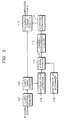
- Figure 3 is a block diagram according to a preferred embodiment of an equalizer for an OFDM receiver; and
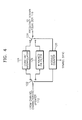
- Figure 4 is a block diagram of a coefficient interpolator shown in Figure 3.
- First, a preferred equalizing method will be described as follows.
- STEP 1: a channel characteristic value in the position of an extracted scattered pilot is estimated by revealing which symbol is received among four symbols and extracting the scattered pilot from the received symbol.
- STEP 2: a channel characteristic value in the position of the scattered pilot having a three sub channel period as shown in Figure 2 is obtained by updating the sub channel through which the scattered pilot is transferred in every symbol into a new value and maintaining the updated value over the next three symbol interval.
- As shown in Figure 2, an upper first symbol shows channel characteristics in the position of scattered pilots having a three sub channel period applied to the symbols starting from a received fifth symbol. The sub channel through which the scattered pilot is transmitted in every symbol is updated to a new value. Over the next three symbol intervals, the updated value is maintained.
- Since the sub channel through which each scattered pilot is transmitted is used for transferring the scattered pilot once every four symbols, when the characteristic of the sub channel through which the scattered pilot is transferred in every symbol is updated to a new value and the value is maintained over four symbols, it is possible to adapt to the change of time of the channel.
- STEP 3: the characteristics of two sub channels through which data between two adjacent scattered pilots are transmitted is estimated by interpolating the channel characteristic value of the position of the scattered pilot estimated in
STEP 2. - Here, in a constant interpolation, the characteristics of three sub channels are calculated in the same manner, considering that the characteristic of a sub channel through which the scattered pilot is transmitted is the same as that of the sub channel through which the following two data are transmitted when the characteristics of the sub channel hardly changes. In another method, the characteristics of the two sub channels through which data are transmitted are calculated by a linear interpolation. In still another method, a windowed finite impulse response (FIR) filter having a higher interpolation performance is used.
- Here, the structure of the equalizer is simple when constant interpolation or linear interpolation are used. However, the accuracy is lower than in the interpolating method according to the windowed FIR filter. When the interpolating method by the windowed FIR filter is used, the accuracy becomes higher. However, an error may be generated in the starting portion of the symbol since the position of the scattered pilot is continuous at the end and the start of the symbol. Therefore, the constant interpolation or the linear interpolation is used at the starting portion of the symbol. The interpolation by the windowed FIR filter is used in the other portions. Accordingly, equalizing performance is improved.
- STEP 4: to estimate the characteristics of the sub channels through which data are transmitted means that the characteristics of all the sub channels are known. Therefore, the amplitude and phase distortion, i.e., the channel distortion, is compensated for by multiplying the transmitted sub channel data by the inverse of the characteristic of the sub channel.
- Since the equalizer compensates for frequency distortion in units of a symbol, in a frequency domain, the following
equation 1 is obtained when the characteristics of a channel, transmitted data, and received data are H(f), X(f), and R(f).
wherein k represents the index of a sub channel. - The sub channel through which a pilot is transmitted can be represented as the following
equation 2. The amplitude characteristics and the phase characteristics of the sub channel can be obtained from theequation 3.
wherein, P(f) represents a scattered pilot.
- In the case of an 8K mode, the number of sub channels obtained from the scattered pilots of a modified distribution shown in Figure 2 is 6816/3. The characteristics of the 6816x2/3 data channel are obtained by an interpolation using the characteristics of the sub channels. The constant interpolation used in every symbol can be represented by the following equation 4.

- A linear interpolation used in every symbol will be described as follows. When the characteristic of a channel through which the scattered pilot is transmitted is HP(k)(f), the characteristic of a channel through which an adjacent next pilot is transmitted is HP(k+1)(f). When the characteristics of the sub channels through which data between the sub channels of the two scattered pilots are transmitted are Hd(1)(f) and Hd(2)(f), they can be obtained through the equations 5 and 6.


- The constant interpolation or the linear interpolation is performed to every starting portion twelve carriers and an interpolation by a windowed FIR filter is performed to the other portions. The windowed FIR filter uses a low pass filter whose sampling frequency is three times a carrier frequency.
- When the characteristics of the scattered pilot are filtered by the windowed FIR filter, the characteristics of the two sub channels between the scattered pilots are calculated and output. Namely, when the characteristics of the filter are F(f), the characteristics of all the channels are obtained by performing a convolution with respect to the characteristics of the scattered pilot and of the filter F(f). Namely, the characteristics of all the channels H(f) can be obtained as follows.

- The equalized output represented in the equation 8 is obtained by obtaining the characteristics of all the sub channels by the above method and multiplying the received data by the inverse of the characteristic of the sub channel.

- Conveniently, it is not necessary to trace the position of the scattered pilot since the position of the scattered pilot does not change. It can be estimated the characteristics of the channel by calculating values between the scattered pilots by constant interpolation or linear interpolation since the distance between the scattered pilots becomes two sub channels.
- However, interpolation by the windowed FIR filter can be used in order to enhance the interpolation performance. When the characteristics of all the sub channels are estimated, the equalization in the frequency domain can be performed by multiplying the received signal by the inverse of the channel characteristics value. The equalization becomes very simple since it has the structure of an equalizer having a one tap filter.
- The equalizer for the OFDM receiver will now be described with reference to Figures. 3 and 4.
- In Figure 3, a
guard interval remover 102 removes a cyclic prefix (CP) corresponding to a guard interval from the received data. Aguard band remover 104 performs a fast Fourier transform (FFT) on data output from theguard interval remover 102 and removes the guard band included in the fast Fourier transformed data in units of one symbol in order to convert the data into the data of a frequency domain since the data output from theguard interval remover 102 is data of a time domain. Here, in the case of an 8K mode, each symbol is formed of 6817 carriers. The symbols are transmitted for a duration Ts. The duration Ts includes an effective symbol part interval for transmitting the 6817 carriers and a guard interval. - A
scattered pilot extractor 106 extracts the scattered pilot from data output from theguard band remover 104, namely, the 6817 carriers in every symbol in the case of an 8K mode. Since the scattered pilots have a boosted power level, thescattered pilot extractor 106 examines a correlation between the data from which the guard band has been removed and a reference sequence, and extracts the scattered pilot. Since the reference sequence is one symbol pattern data among four symbols, it is possible to find out which is the symbol received at present among the four symbols. Since the scattered pilot is repeated over a four symbol period, the position of the scattered pilot of the four symbols is automatically revealed by revealing the position of the scattered pilot of one symbol. Therefore, it is possible to correctly reveal the position of the scattered pilot of one symbol using the reference sequence by thescattered pilot extractor 106. With respect to the next three symbols, the received level value is output in the already revealed position of the scattered pilot. - Here, the boosted power level of the received scattered pilot is (4/3)2. However, the scattered pilot according to the positions of the respective scattered pilots of the four symbol period during transmission has a coordinate value of (4/3,0) or (-4/3,0). Since this coordinate value, i.e., phase information, is already revealed by a
scattered pilot determiner 108, the coordinate value of the scattered pilot extracted from the scatteredpilot extractor 106 is output to achannel estimator 110. - The
channel estimator 110 outputs the channel characteristic value in the position of the scattered pilot by channel estimating using a coordinate value according to the position of the scattered pilot output from the scatteredpilot determiner 108. Namely, thechannel estimator 110 compares the boosted level of the scattered pilot extracted by thescattered pilot extractor 106 with the original coordinate value and outputs a value (r) for compensating for the amplitude distortion and a value (θ) for compensating for the phase distortion. - A channel
characteristic updater 112 updates the channel characteristic value of the sub channel through which each scattered pilot is transmitted into a new value in every symbol and maintains the updated value during the next three symbols. By doing so, an equalizing coefficient is updated into a new value in the scattered pilot position of the 12 sub channel distance in every symbol. The equalizing coefficients in the remaining scattered pilot positions maintain their previous values. The distance between the sub channels through which the scattered pilots are transmitted is two sub channels. However, the current channel characteristics of the scattered pilot are reflected by 1/4 (12 sub channel distance) in every symbol. Accordingly, it is possible to adapt to the characteristics of the channel changing as time goes by. - A coefficient interpolator 114 performs linear interpolation, constant interpolation or windowed FIR filter interpolation on the basis of the channel characteristic value in the pilot position of the three sub channel period in which the channel characteristics of the scattered pilots are updated by a distance of 12 sub channels in every symbol provided from the channel
characteristic updater 112, and outputs the interpolated coefficients in order to estimate the sub channel characteristics of the data of the two sub channels between pilots. - A
frequency domain equalizer 116 can be constructed of a filter having one tap, namely, a multiplier. Thefrequency domain equalizer 116 outputs data compensated by multiplying the data output from theguard band remover 104 by the inverse of the coefficient interpolated by the coefficient interpolator 114. - Figure 4 is a block diagram of the coefficient interpolator 114 shown in Figure 3. In Figure 4, a modulo
counter 120 modulo counts the output of the channelcharacteristic updater 112 shown in Figure 3 according to a symbol synchronizing signal from 0 to 6816 since one symbol is comprised of 6817 effective carriers and generates a select control signal when numbers to a predetermined number (here, 11) in the starting portion of every symbol are counted. - A
divider 122 constituted of a demultiplexer outputs to aconstant interpolator 124 the channel characteristic values in the starting portion of every symbol among the channel characteristic values in the scattered pilot position output from the channelcharacteristic updater 112 according to the select control signal output from themodulo counter 120, and outputs the remaining channel characteristic values to awindowed FIR filter 126. Theconstant interpolator 124 can be replaced by a linear interpolator. Thewindowed FIR filter 126 is constituted of a low pass filter whose sampling frequency is three times the carrier frequency. - A
selector 128 constituted of a multiplexer selects the output of theconstant interpolator 124 in the case of the starting portion of a symbol according to the select control signal generated by themodulo counter 120, otherwise selects thewindowed FIR filter 126, and outputs the selected signal to thefrequency domain equalizer 116 shown in Figure 3. Figure 4 shows thedivider 122 and theselector 128. However, thedivider 122 may be omitted. - In the equalizing method described above, the amount of calculating is reduced by reducing the distance between scattered pilots, adapting to the channel changing as time goes by. Also, the structure of the interpolator employed in the equalizer described above is simple, since only the characteristics of two data sub channels are interpolated. It is possible to improve the performance of the equalizer by operating two types of interpolators.
Claims (16)
- An equalizing method for compensating for channel distortion in a plurality of carriers transmitted through a plurality of sub channels using scattered pilots having a period of a first predetermined number of symbols, comprising the steps of:(a) extracting (106) scattered pilots from a plurality of received carriers and estimating a channel characteristic value in the position of an extracted scattered pilot; and further characterized by the steps of:(b) providing (112) a channel characteristic value in a scattered pilot position having a period of a third predetermined number of sub channels by updating the channel characteristic value of the scattered pilot position having a period of a second predetermined number of sub channels in every symbol, and by maintaining a previous channel characteristic value in the remaining scattered pilots;(c) providing (114) the characteristic values of all the sub channels by estimating the characteristics of a sub channel through which data between scattered pilots is transmitted using the channel characteristic values in the scattered pilot position having the period of the third predetermined number of sub channels; and(d) compensating (116) for the channel distortion of the received plurality of carriers on the basis of all the sub channel characteristic values.
- The method of claim 1, wherein an updated channel characteristic value of the scattered pilot of the period of the second predetermined number of sub channels is maintained during the first predetermined number of symbols in the step (b).
- The method of claim 1 or 2, wherein the channel characteristic values in the scattered pilot position having the period of the third predetermined number of sub channels are interpolated by a predetermined interpolation and interpolated coefficient is output in order to estimate the characteristics of the sub channels through which data between the scattered pilots is transmitted, in the step (c).
- The method of claim 3, wherein the channel distortion is compensated for by multiplying the received carrier by the inverse of the interpolated coefficient in the step (d).
- The method of claim 3 or 4, wherein the predetermined interpolation is one among a constant interpolation, a linear interpolation, and a windowed FIR filtering interpolation.
- The method of claim 5, wherein one of constant interpolation and linear interpolation is used with respect to a predetermined number of carriers in the starting portion of every symbol and interpolation by windowed FIR filtering is used with respect to the remaining carriers, in the step (c).
- The method of any of claims 1 to 6, wherein the first predetermined number is 4, the second predetermined number is 12, and the third predetermined number is 3.
- An equalizer for an OFDM receiver for receiving a plurality of carriers including a scattered pilot having a period of a first predetermined number of symbols through a plurality of sub channels, comprising:an extractor (106) for extracting a scattered pilot from a plurality of received carriers;a channel estimator (110) for estimating a channel characteristic value in the position of the extracted scattered pilot using a coordinate value of the already revealed scattered pilot;and further characterized by:a channel characteristic updater (112) for updating the channel characteristic value of the scattered pilot position having a period of a second predetermined number of sub channels in every symbol, maintaining a previous channel characteristic value with respect to the remaining scattered pilots, and providing the channel characteristic value in the scattered pilot position having a period of a third predetermined number of sub channels;an interpolator (114) for interpolating the channel characteristic value in the scattered pilot position having the period of the third predetermined number of sub channels and providing an interpolated coefficient; anda digital filter (116) for multiplying the received plurality of carriers by the inverse of the interpolated coefficient and outputting data in which the channel distortion is compensated for.
- The equalizer of claim 8, further comprising a scattered pilot determiner (108) for generating a coordinate value according to the position of the already revealed scattered pilot and outputting the coordinate value to the channel estimator.
- The equalizer of claim 8 or 9, wherein the extractor (106) examines a correlation between the plurality of received carriers and a reference sequence and extracts a scattered pilot, and wherein the reference sequence is one symbol pattern data among the first predetermined number of symbols.
- The equalizer of any of claims 8 to 10, wherein the digital filter (116) comprises a multiplier for multiplying the plurality of received carriers by the inverse of the interpolated coefficient.
- The equalizer of any of claims 8 to 11, wherein the interpolation (114) is one among constant interpolation (124), linear interpolation, and windowed FIR filter interpolation (126).
- The equalizer of any of claims 8 to 12, wherein the interpolator (114) comprises:a modulo counter (120) for modulo counting effective carriers of one symbol and generating a selection control signal when a first predetermined number of carriers in the starting portion of every symbol are counted;a constant interpolator (124) for interpolating the characteristic value of the sub channels of the data between the scattered pilots into the same value as the channel characteristic value of the previous scattered pilot position output from the channel characteristic updater;a windowed FIR filter (126) for interpolating the characteristic values of the sub channels of the data between the scattered pilots by filtering the channel characteristic values in the scattered pilot position of the period of a second predetermined number of sub channels, adjacent to said predetermined first number of carriers, output from the channel characteristic updater; anda selector (128) for selecting the output of the constant interpolator in the starting portion of the symbol and the output of the windowed FIR filter in the other portions of the symbol, according to the selection control signal.
- The equalizer of claim 13, wherein the windowed FIR filter (126) is a low pass filter whose sampling frequency is third predetermined number of times the carrier frequency.
- The equalizer of any of claims 8 to 13, wherein the interpolator comprises:a modulo counter (120) for modulo counting effective carriers of one symbol and generating a selection control signal when a predetermined number of carriers in the starting portion of every symbol are counted;a linear interpolator for linear interpolating the channel characteristic value of the adjacent scattered pilot position output from the channel characteristic updater;a windowed FIR filter (126) for interpolating the characteristic values of the sub channels of the data between the scattered pilots by filtering the channel characteristic values in the adjacent scattered pilot position output from the channel characteristic updater; anda selector (128) for selecting the output of the linear interpolator in the starting portion of the symbol and the output of the windowed FIR filter in the other portions, according to the selection control signal.
- The equalizer of any of claims 8 to 15, wherein the first predetermined number is 4, the second predetermined number is 12, and the third predetermined number is 3.
Applications Claiming Priority (2)
| Application Number | Priority Date | Filing Date | Title |
|---|---|---|---|
| KR1019970039661A KR100224864B1 (en) | 1997-08-20 | 1997-08-20 | Equalization Methods and Equalizers for OFDM Receivers |
| KR9739661 | 1997-08-20 |
Publications (3)
| Publication Number | Publication Date |
|---|---|
| EP0898381A2 EP0898381A2 (en) | 1999-02-24 |
| EP0898381A3 EP0898381A3 (en) | 2002-10-02 |
| EP0898381B1 true EP0898381B1 (en) | 2006-11-15 |
Family
ID=19517923
Family Applications (1)
| Application Number | Title | Priority Date | Filing Date |
|---|---|---|---|
| EP98306336A Expired - Lifetime EP0898381B1 (en) | 1997-08-20 | 1998-08-07 | Equalizing method and equalizer for ofdm receiver |
Country Status (6)
| Country | Link |
|---|---|
| EP (1) | EP0898381B1 (en) |
| JP (1) | JP3027362B2 (en) |
| KR (1) | KR100224864B1 (en) |
| CN (1) | CN1123997C (en) |
| AU (1) | AU701160B1 (en) |
| DE (1) | DE69836400T2 (en) |
Families Citing this family (30)
| Publication number | Priority date | Publication date | Assignee | Title |
|---|---|---|---|---|
| GB2340000B (en) * | 1998-07-02 | 2003-06-18 | Lsi Logic Corp | Storing digital video braodcast signals |
| EP1041734A1 (en) * | 1999-03-31 | 2000-10-04 | Alcatel | Radio transmission method in a wireless telecommunications system with pilot and data channels estimation |
| US6493329B1 (en) * | 1999-08-23 | 2002-12-10 | Qualcomm Incorporated | Adaptive channel estimation in a wireless communication system |
| US6650617B1 (en) | 2000-02-22 | 2003-11-18 | Thomson Licensing S.A. | Reduced complexity FFT window synchronization for an orthogonal frequency division multiplexing system |
| EP1170897B1 (en) | 2000-07-05 | 2020-01-15 | Wi-Fi One Technologies International Limited | Pilot pattern design for a STTD scheme in an OFDM system |
| US6771591B1 (en) | 2000-07-31 | 2004-08-03 | Thomson Licensing S.A. | Method and system for processing orthogonal frequency division multiplexed signals |
| EP1313242A4 (en) * | 2000-08-21 | 2009-11-25 | Kenwood Corp | Orthogonal frequency division multiplexed signal receiving apparatus and orthogonal frequency division multiplexed signal receiving method |
| KR100360273B1 (en) * | 2000-12-28 | 2002-11-09 | 엘지전자 주식회사 | Linear compensation adaptive equalizer apparatus and his controll method for digital television repeater |
| KR20030014078A (en) * | 2001-08-10 | 2003-02-15 | 최승국 | OFDM wireless transmission system using MMSE channel estimation |
| WO2003017607A2 (en) * | 2001-08-14 | 2003-02-27 | Redline Communications Inc. | Iterative calculation of coefficients for a multicarrier equaliser |
| JP3870116B2 (en) * | 2002-03-26 | 2007-01-17 | 株式会社ケンウッド | Equalizer |
| KR20030090382A (en) * | 2002-05-23 | 2003-11-28 | 주식회사 신영텔레콤 | Apparatus for equalization of system which is using orthogonal frequency division multiplexing |
| KR100824367B1 (en) * | 2002-05-24 | 2008-04-22 | 삼성전자주식회사 | OPM transmitter and signal processing method thereof |
| KR20030095665A (en) * | 2002-06-14 | 2003-12-24 | 삼성전자주식회사 | OFDM recevier |
| CN1497886B (en) * | 2002-10-10 | 2012-03-07 | 松下电器产业株式会社 | Orthogonal frequency division multiplex signal equalizer, method, ground digital broadcast receiver |
| CN100505596C (en) * | 2003-06-10 | 2009-06-24 | 北京邮电大学 | A Channel Estimation Method Applicable to Orthogonal Frequency Division Multiple Access System |
| US8526412B2 (en) * | 2003-10-24 | 2013-09-03 | Qualcomm Incorporated | Frequency division multiplexing of multiple data streams in a wireless multi-carrier communication system |
| KR100913874B1 (en) * | 2003-10-27 | 2009-08-26 | 삼성전자주식회사 | Interference Cancellation Method between Subchannels in Orthogonal Frequency Division Multiplexing System |
| JP4446072B2 (en) | 2004-07-23 | 2010-04-07 | 株式会社ディーアンドエムホールディングス | Audio signal output device |
| JP2006042025A (en) * | 2004-07-28 | 2006-02-09 | Casio Comput Co Ltd | Ofdm signal demodulation circuit and method for demodulating ofdm signal |
| EP1845636A4 (en) * | 2005-02-03 | 2012-03-14 | Fujitsu Ltd | SYSTEM AND METHOD FOR WIRELESS COMMUNICATION |
| DE602006004975D1 (en) | 2005-03-01 | 2009-03-12 | Panasonic Corp | OFDM receiver and reception method |
| KR100744525B1 (en) * | 2006-01-13 | 2007-08-01 | 엘지전자 주식회사 | Equalizer |
| KR100678053B1 (en) * | 2006-02-08 | 2007-02-02 | 삼성전자주식회사 | Device and method for compensating for distortion of signal in fixed broadband wireless access system |
| CN101361304A (en) | 2006-05-24 | 2009-02-04 | 松下电器产业株式会社 | OFDM demodulation device |
| WO2008089595A1 (en) * | 2007-01-19 | 2008-07-31 | Thomson Licensing | Time domain interpolation method and apparatus for channel estimation |
| JP2009065393A (en) * | 2007-09-05 | 2009-03-26 | Toyota Central R&D Labs Inc | Demodulation method and demodulator |
| US8300726B2 (en) * | 2007-11-02 | 2012-10-30 | Alcatel Lucent | Interpolation method and apparatus for increasing efficiency of crosstalk estimation |
| CN105610517B (en) * | 2014-11-14 | 2018-05-08 | 中兴通讯股份有限公司 | The iteration post-equalization of coherent optical heterodyne communicatio |
| EP3276972B1 (en) * | 2015-03-24 | 2020-09-02 | LG Electronics Inc. | Device and method for receiving digital broadcast signal |
Family Cites Families (5)
| Publication number | Priority date | Publication date | Assignee | Title |
|---|---|---|---|---|
| EP0613267A3 (en) * | 1993-02-08 | 1996-12-04 | Philips Nv | MDFO system with crosstalk reduction. |
| FR2738095B1 (en) * | 1995-08-21 | 1997-11-07 | France Telecom | METHOD AND DEVICE FOR DEMODULATING A MULTI-CARRIER SIGNAL TAKING INTO ACCOUNT AN ESTIMATION OF THE RESPONSE OF THE TRANSMISSION CHANNEL AND AN ESTIMATON OF A WHITE FREQUENCY DISTORTION |
| JP2802255B2 (en) * | 1995-09-06 | 1998-09-24 | 株式会社次世代デジタルテレビジョン放送システム研究所 | Orthogonal frequency division multiplexing transmission system and transmission device and reception device using the same |
| IT1281389B1 (en) * | 1995-11-03 | 1998-02-18 | Dante Tognetti | METHOD FOR AUTOMATICALLY OBTAINING THE COEFFICIENTS OF AN EQUALIZING NETWORK IN A DATA TRANSMISSION SYSTEM IN CLOSED FORM |
| FR2743967B1 (en) * | 1996-01-18 | 1998-03-27 | France Telecom | METHOD AND DEVICE FOR TIME SYNCHRONIZATION OF A RECEIVER OF A MULTI-CARRIER SIGNAL |
-
1997
- 1997-08-20 KR KR1019970039661A patent/KR100224864B1/en not_active Expired - Fee Related
-
1998
- 1998-07-28 AU AU78435/98A patent/AU701160B1/en not_active Ceased
- 1998-08-04 JP JP10220785A patent/JP3027362B2/en not_active Expired - Fee Related
- 1998-08-07 DE DE69836400T patent/DE69836400T2/en not_active Expired - Lifetime
- 1998-08-07 EP EP98306336A patent/EP0898381B1/en not_active Expired - Lifetime
- 1998-08-19 CN CN98118460A patent/CN1123997C/en not_active Expired - Fee Related
Also Published As
| Publication number | Publication date |
|---|---|
| AU701160B1 (en) | 1999-01-21 |
| CN1123997C (en) | 2003-10-08 |
| KR100224864B1 (en) | 1999-10-15 |
| JP3027362B2 (en) | 2000-04-04 |
| EP0898381A3 (en) | 2002-10-02 |
| JPH11150494A (en) | 1999-06-02 |
| EP0898381A2 (en) | 1999-02-24 |
| CN1209007A (en) | 1999-02-24 |
| DE69836400T2 (en) | 2007-09-27 |
| KR19990016931A (en) | 1999-03-15 |
| DE69836400D1 (en) | 2006-12-28 |
Similar Documents
| Publication | Publication Date | Title |
|---|---|---|
| EP0898381A2 (en) | Equalizing method and equalizer for ofdm receiver | |
| EP0903898B1 (en) | Equalizing method and equalizer for OFDM receiver | |
| KR100589678B1 (en) | Uplink Channel Estimation System and Method for Orthogonal Frequency Division Multiple Access System | |
| US8406355B2 (en) | Method and apparatus for channel estimation in OFDM | |
| US8345782B2 (en) | Method and apparatus for channel estimation | |
| KR101339425B1 (en) | Method of estimating Inter-Carrier Interference and ICI mitigating equalizer | |
| US20080219144A1 (en) | Timing adjustments for channel estimation in a multi carrier system | |
| KR20070082048A (en) | Channel Estimation Method and Apparatus using Linear Interpolation in Orthogonal Frequency Division Multiplexing System and Receiver Using the Same | |
| KR100226708B1 (en) | Address generator for counting memory of quadrature division band channel equalizer | |
| US20070076804A1 (en) | Image-rejecting channel estimator, method of image-rejection channel estimating and an OFDM receiver employing the same | |
| KR101126989B1 (en) | Timing adjustments for channel estimation in a multi carrier system | |
| KR100664600B1 (en) | Curve Junction Channel Estimation Method in OFDM Systems | |
| EP2169891A2 (en) | Information processor and corresponding method, display device and program | |
| KR20000010178A (en) | Equalizing method and equalizer for a ofdm receiver | |
| EP1821407B1 (en) | OFDM channel estimation systems | |
| EP2685686B1 (en) | Method and apparatus for channel estimation based on estimated auto correlation | |
| WO1998032267A1 (en) | Ofdm receiver using pilot carriers | |
| EP2077625B1 (en) | Matched filter and receiver | |
| DE10324418B4 (en) | Apparatus and method for determining a scan error and means for correcting it | |
| KR100977557B1 (en) | Apparatus and Method for Time-variable Channel Estimation in Orthogonal Frequency Division Multiplexing System | |
| EP2007093A1 (en) | Method and apparatus for attenuating out-of-band signals of a multi-carrier symbol signal |
Legal Events
| Date | Code | Title | Description |
|---|---|---|---|
| PUAI | Public reference made under article 153(3) epc to a published international application that has entered the european phase |
Free format text: ORIGINAL CODE: 0009012 |
|
| 17P | Request for examination filed |
Effective date: 19980817 |
|
| AK | Designated contracting states |
Kind code of ref document: A2 Designated state(s): AT BE CH CY DE DK ES FI FR GB GR IE IT LI LU MC NL PT SE |
|
| AX | Request for extension of the european patent |
Free format text: AL;LT;LV;MK;RO;SI |
|
| PUAL | Search report despatched |
Free format text: ORIGINAL CODE: 0009013 |
|
| AK | Designated contracting states |
Kind code of ref document: A3 Designated state(s): AT BE CH CY DE DK ES FI FR GB GR IE IT LI LU MC NL PT SE |
|
| AX | Request for extension of the european patent |
Free format text: AL;LT;LV;MK;RO;SI |
|
| RIC1 | Information provided on ipc code assigned before grant |
Free format text: 7H 04B 7/005 A, 7H 04L 27/26 B |
|
| AKX | Designation fees paid |
Designated state(s): DE FR GB |
|
| 17Q | First examination report despatched |
Effective date: 20050519 |
|
| GRAP | Despatch of communication of intention to grant a patent |
Free format text: ORIGINAL CODE: EPIDOSNIGR1 |
|
| GRAS | Grant fee paid |
Free format text: ORIGINAL CODE: EPIDOSNIGR3 |
|
| GRAA | (expected) grant |
Free format text: ORIGINAL CODE: 0009210 |
|
| AK | Designated contracting states |
Kind code of ref document: B1 Designated state(s): DE FR GB |
|
| REG | Reference to a national code |
Ref country code: GB Ref legal event code: FG4D |
|
| REF | Corresponds to: |
Ref document number: 69836400 Country of ref document: DE Date of ref document: 20061228 Kind code of ref document: P |
|
| ET | Fr: translation filed | ||
| PLBE | No opposition filed within time limit |
Free format text: ORIGINAL CODE: 0009261 |
|
| STAA | Information on the status of an ep patent application or granted ep patent |
Free format text: STATUS: NO OPPOSITION FILED WITHIN TIME LIMIT |
|
| 26N | No opposition filed |
Effective date: 20070817 |
|
| REG | Reference to a national code |
Ref country code: FR Ref legal event code: PLFP Year of fee payment: 18 |
|
| PGFP | Annual fee paid to national office [announced via postgrant information from national office to epo] |
Ref country code: DE Payment date: 20150722 Year of fee payment: 18 Ref country code: GB Payment date: 20150721 Year of fee payment: 18 |
|
| PGFP | Annual fee paid to national office [announced via postgrant information from national office to epo] |
Ref country code: FR Payment date: 20150625 Year of fee payment: 18 |
|
| REG | Reference to a national code |
Ref country code: DE Ref legal event code: R119 Ref document number: 69836400 Country of ref document: DE |
|
| GBPC | Gb: european patent ceased through non-payment of renewal fee |
Effective date: 20160807 |
|
| REG | Reference to a national code |
Ref country code: FR Ref legal event code: ST Effective date: 20170428 |
|
| PG25 | Lapsed in a contracting state [announced via postgrant information from national office to epo] |
Ref country code: FR Free format text: LAPSE BECAUSE OF NON-PAYMENT OF DUE FEES Effective date: 20160831 Ref country code: GB Free format text: LAPSE BECAUSE OF NON-PAYMENT OF DUE FEES Effective date: 20160807 Ref country code: DE Free format text: LAPSE BECAUSE OF NON-PAYMENT OF DUE FEES Effective date: 20170301 |