EP0897883A1 - Method and device for positioning in an automatic pile changer - Google Patents
Method and device for positioning in an automatic pile changer Download PDFInfo
- Publication number
- EP0897883A1 EP0897883A1 EP98113046A EP98113046A EP0897883A1 EP 0897883 A1 EP0897883 A1 EP 0897883A1 EP 98113046 A EP98113046 A EP 98113046A EP 98113046 A EP98113046 A EP 98113046A EP 0897883 A1 EP0897883 A1 EP 0897883A1
- Authority
- EP
- European Patent Office
- Prior art keywords
- stack
- pallet
- support plate
- sensor
- grooves
- Prior art date
- Legal status (The legal status is an assumption and is not a legal conclusion. Google has not performed a legal analysis and makes no representation as to the accuracy of the status listed.)
- Granted
Links
Images


Classifications
-
- B—PERFORMING OPERATIONS; TRANSPORTING
- B65—CONVEYING; PACKING; STORING; HANDLING THIN OR FILAMENTARY MATERIAL
- B65H—HANDLING THIN OR FILAMENTARY MATERIAL, e.g. SHEETS, WEBS, CABLES
- B65H1/00—Supports or magazines for piles from which articles are to be separated
- B65H1/26—Supports or magazines for piles from which articles are to be separated with auxiliary supports to facilitate introduction or renewal of the pile
- B65H1/263—Auxiliary supports for keeping the pile in the separation process during introduction of a new pile
-
- B—PERFORMING OPERATIONS; TRANSPORTING
- B65—CONVEYING; PACKING; STORING; HANDLING THIN OR FILAMENTARY MATERIAL
- B65H—HANDLING THIN OR FILAMENTARY MATERIAL, e.g. SHEETS, WEBS, CABLES
- B65H2301/00—Handling processes for sheets or webs
- B65H2301/40—Type of handling process
- B65H2301/42—Piling, depiling, handling piles
- B65H2301/422—Handling piles, sets or stacks of articles
- B65H2301/4225—Handling piles, sets or stacks of articles in or on special supports
- B65H2301/42256—Pallets; Skids; Platforms with feet, i.e. handled together with the stack
-
- B—PERFORMING OPERATIONS; TRANSPORTING
- B65—CONVEYING; PACKING; STORING; HANDLING THIN OR FILAMENTARY MATERIAL
- B65H—HANDLING THIN OR FILAMENTARY MATERIAL, e.g. SHEETS, WEBS, CABLES
- B65H2511/00—Dimensions; Position; Numbers; Identification; Occurrences
- B65H2511/20—Location in space
-
- B—PERFORMING OPERATIONS; TRANSPORTING
- B65—CONVEYING; PACKING; STORING; HANDLING THIN OR FILAMENTARY MATERIAL
- B65H—HANDLING THIN OR FILAMENTARY MATERIAL, e.g. SHEETS, WEBS, CABLES
- B65H2511/00—Dimensions; Position; Numbers; Identification; Occurrences
- B65H2511/50—Occurence
- B65H2511/51—Presence
- B65H2511/512—Marks, e.g. invisible to the human eye; Patterns
-
- B—PERFORMING OPERATIONS; TRANSPORTING
- B65—CONVEYING; PACKING; STORING; HANDLING THIN OR FILAMENTARY MATERIAL
- B65H—HANDLING THIN OR FILAMENTARY MATERIAL, e.g. SHEETS, WEBS, CABLES
- B65H2801/00—Application field
- B65H2801/03—Image reproduction devices
- B65H2801/21—Industrial-size printers, e.g. rotary printing press
Definitions
- the invention relates to a method and a device for aligning a automatic stack changer according to the preamble of the process or Device claim.
- the sheets to be printed are printed by the Removed the top of a feeder stack and a conveyor table to one Plant transported.
- sheetfed offset printing presses in the order of 1mm and more processed and also with a high Printing speed can be conveyed through the machine (10,000 to 15,000 Sheets / h), the stacks in the feeder of the machine are processed relatively quickly.
- Automatic stack changing devices are for this purpose have been developed, by means of those which have been processed to the rest Stack (residual stack) removed from the pallet on the stack support plate and after lowering the stack support plate and putting on a new one Main stack again placed exactly on top of a new main stack can be.
- These known stack changing devices work in particular together with horizontally movable bars in the manner of a rake, wherein these rods receiving the remaining stack on a vertically movable Auxiliary stack support device are attached.
- the unpublished DE 197 04 285 A1 shows such a stack changing device for the sheet feeder of a sheetfed offset press, at which combines the rods of the auxiliary stack support device individually and / or in groups are designed to be retractable for lifting off the remaining stack.
- the the stack-receiving pallets have a groove profile on their top, the grooves run in the direction of the retractable and extendable rods.
- the auxiliary stack support device is positioned at such a height level that the bars are exactly at the level of the grooves between those carrying the stack Can immerse webs. For this purpose it is necessary after lowering the stack support plate with a new pallet, this pallet with the Align the new stack precisely with the bars of the auxiliary stack support device. If this does not happen, the rods may collide with the webs of the Pallet (groove profile) and thus considerable damage.
- a simple alignment option results from the fact that the lowered on the Stacking pallet new pallet to be placed with the one on it Stack is brought exactly into a predetermined position, that is, by the operator parked exactly in the space provided for this using a pallet truck must become. This makes handling relatively time consuming and cumbersome furthermore, this extends the entire stack changing process Time available so that overall larger residual stacks from the auxiliary stack support device are included and the frequency of automatic Stack change increases.
- a distance measuring system is known from DE 4 129 702 C2, which in particular the special application of stack alignment in an automatic Stack changer is used.
- This system consists of two after the Triangulation principle working measuring channels, through which the distance to the side surface of the remaining stack or that of the main stack is detectable in order to these stacks then relative to one another via corresponding positioning devices align.
- this special measurement system no one succeeds Alignment of an auxiliary stack support device with horizontally movable bars relative to a pallet with a groove profile on the top.
- the object of the present invention is therefore a method and a device to align an automatic stack changer according to the generic term to expand the process or device claim in such a way, so that while avoiding the disadvantages mentioned above, a simple and safe positioning of the bars of the auxiliary stack support device to the corresponding structured surface of the pallets receiving the main stack is guaranteed.
- the position of this new pallet is sensed, to determine the amount of travel towards the A or B side of the bars
- the auxiliary stack support device must be moved precisely into the grooves to be able to dip between the webs on the top of the pallet.
- this is achieved in a first preferred embodiment by that in the lower area of the feeder is designed as a reflection light sensor Sensor is arranged by means of the lateral orientation of the pallet or the groove profile with the main stack on the stack support plate is noticeable.
- This reflection light scanner is one of these Height in the lower area of the feeder, preferably arranged in the middle thereof, so that after placing a new pallet on top of it located stack and lifting the stack support plate by a predetermined the effective sensing range exactly at the height of the groove profile the pallet lies. Then the stack support plate by predetermined travel amounts move in the direction of the A and / or B side, that due to the key signals the position of the grooves or the webs between them can be determined by the sensor is.
- the stack support plate To determine the position of a groove, it may be sufficient to use the stack support plate only move in one direction (e.g. A-side) to get out of the Signal change of the sensor to determine the position of the groove. A higher accuracy results, however, when the stack support plate by predetermined travel amounts is moved in both directions and thus from the signal curve of the Sensors in connection with the control signals for the pos drive of the stack support plate the center of a groove is determined.
- one direction e.g. A-side
- the stacking support plate can be put back into the Basic position (middle of feeder). From the situation at least one Groove or a web can then be determined by how much the bars or the whole Auxiliary stack support device must be moved in the direction of the A or B side (starting from a zero position), so that to remove the remaining stack Can insert rods precisely into the grooves of the pallet. In this from the location The support rods remain in the pallet on the position dependent on the stack support plate then until a new run-in, i.e. until a new pallet with new stack is put on. After removing the remaining stack from the pallet the new main stack is turned into one by lateral alignment movements Remaining stack spent congruent position, for which the side edges of the rest and Main stack scanning detectors are provided.
- the pallet is measured by a in the lower area of the Sensor arranged by the investor (diffuse sensor).
- the one with the Interaction of the top of the pallet in the area of the groove profile is due to the Periodicity of the groove profile the minimum displacement of the support rods of the auxiliary stack support device can be determined so that they collision-free in the between the Grooves located on the top of the pallet can dip.
- this one sensor can also determine whether the pallet is in one correct orientation to the stack support plate has been placed, in particular whether the edge of the pallet is parallel or sufficiently parallel to a corresponding one Aligning edge of the stack support plate runs.
- a sensor can also determine whether the correct pallet type is used at all a pallet, which has the one to be measured on its top Has groove profile. This would be without any groove profile when using a pallet on the top by measuring the Stack support plate no change of the tactile signal detectable when moving the pallet.
- the orientation the pallet placed on the stack support plate by means of two of them spacing sensors.
- the corresponding Travel signal of the drive of the lateral positioning device Stack support plate in connection with the signals from the sensors the travel amount determines by which the bars or the entire auxiliary stack support device with the rods contained in it must be moved in the direction of the A or B side.
- the stack support plate of the main stack is moved back to the zero position are then aligned laterally over the stack support plate be that the side edges of the main stack with the through the support rods of the Auxiliary stack support device collapsed remaining stack (align). Then the remaining stack is combined with the new main stack by pulling out the bars of the auxiliary stack support.
- the stack support plate and the auxiliary stack support device move as long as synchronous, i.e. the corresponding drives are sensory Move the top edge of the stack synchronously until the remaining stack has reached an intended minimum height, whereupon the stack support plate lowered and loaded into a new pallet together with the main stack Basic position is moved on the ground. After placing a new stack In addition to the pallet, the position of the pallet is then measured around the Insert the support rods into the grooves on the top of the pallet without collision can.
- a sheetfed offset printing machine 1 is fed by a feeder 2 in between located conveyor table arch fed. This will be done in investor 2 4 sheets from the top of a stack by means of sheet separation devices S taken (Fig. 1).
- the main stack S in the feeder 2 is by means of a pallet P on a lifting device, not shown, can be raised and lowered Stacking support plate ST set up.
- An auxiliary stack carrier 3 is arranged upstream of the feeder 2, which can be raised and lowered via guide rails 8 of a lifting device 5 is.
- the auxiliary stack carrier 3 has a frame 6, in which horizontally movable Support rods 7 are arranged, which in the illustration according to FIG. 1 in the retracted position are within the frame 6.
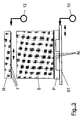
- the pallets P receiving the main stack S on the stack support plate ST have a plurality of grooves N running parallel to one another on the upper side thereof with each remaining in between and bearing the underside of the main stack S.
- the distance and width of the grooves N as well correspondingly the width of the intermediate webs carrying the stack SG is on the distance and the width of the support rods 7 of the auxiliary stack carrier 3rd Voted.
- Figures 3 and 4 show the through the support rods 7 of the auxiliary stack carrier 3rd held remaining stack 1 above the main stack S.
- a new stack S with a pallet P set up The stack support plate ST is then in a predetermined height position have been moved above the basic position, so that by an im lower region of the feeder 2 arranged sensor 9, which acts as an optical diffuse sensor (Distance measuring system) is formed, the profile of the grooves N and the webs SG lying therebetween are opposite the effective range of the sensor 9.
- the control 11 for the automatic stack change the drive 10 for the side alignment of the stack support plate ST is controlled in this way, so that the stack support plate ST in by a predetermined amount Is moved towards the A and / or B side.
- a diffuse sensor trained sensor 9 can be determined at which travel of the as a positioning drive trained drive 10 an edge of the transition between Groove N and web SG of the pallet P occur, i.e. the amount by which the pallet P on the stacking support plate ST is too different so that it is exactly in the middle of the format the sensor 2 arranged sensor 9 of a groove N of the pallet P is opposite. This is present when the edge of the output signal of sensor 9 changes Displacement is detected and stored by the controller 11.
- the Stack support plate ST has additional facilities and markings (not shown), by means of which a pallet P with a stack S thereon at least approximately in the middle of the stack support plate ST and thus the feeder 2 can be set up.
- the lateral movement of the pallet P, the stack support plate ST and the stack S to determine the necessary orientation of the support rods 7 of the auxiliary stack carrier 3 is additionally shown again in FIG. 2 in a view from above.
- the stack support plate ST in a basic position is located in the middle of the feeder 2.
- the stack support plate can also be moved back to the basic position.
- the support rods 7 of the auxiliary stack carrier 3 are in front of the lateral alignment corresponding to the necessary shift in detected by the sensor 9 a basic position (zero position).
- the drive 10 for the side alignment the stack support plate ST in addition to the measurement according to the invention described above the position of the grooves N / webs SG of the pallet P also the side orientation of the stack S takes place before the union with the remaining stack R. Every new one Stack S is thus individual with respect to that held by the support rods Remaining stack R aligned.
Abstract
Description
Die Erfindung betrifft ein Verfahren und eine Vorrichtung zur Ausrichtung eines automatischen Stapelwechslers gemäß dem Oberbegriff des Verfahrens- bzw. Vorrichtungsanspruches.The invention relates to a method and a device for aligning a automatic stack changer according to the preamble of the process or Device claim.
Bei Bogenoffsetdruckmaschinen werden die zu bedruckenden Bogen von der Oberseite eines Anlegerstapels entnommen und über einen Fördertisch zu einer Anlage transportiert. Da bei Bogenoffsetdruckmaschinen Bedruckstoffstärken in der Größenordnung von 1mm und mehr verarbeitet und auch mit einer hohen Druckgeschwindigkeit durch die Maschine gefördert werden (10.000 bis 15.000 Bogen/h), sind die Stapel im Anleger der Maschine relativ schnell abgearbeitet. Um den Auflagedruck ohne Unterbrechung fortführen zu können, ist es nötig, einen neuen Stapel auf der Stapeltragplatte bereitzustellen, d.h diesen neuen Stapel genau in der gleichen Position unterhalb des Reststapels (vorheriger abgearbeiteter Stapel) zu positionieren und sodann den Reststapel mit dem neuen Hauptstapel zu vereinigen. Zu diesem Zweck sind automatische Stapelwechselvorrichtungen entwickelt worden, vermittels denen der bis auf einen Rest abgearbeiteter Stapel (Reststapel) von der Palette auf der Stapeltragplatte abgenommen und nach dem Absenken der Stapeltragplatte sowie dem Aufsetzen eines neuen Hauptstapels wieder lagegenau auf der Oberseite eines neuen Hauptstapels aufgelegt werden kann. Diese bekannten Stapelwechselvorrichtungen arbeiten insbesondere mit horizontal verfahrbaren Stäben nach Art eines Rechens zusammen, wobei diese den Reststapel aufnehmenden Stäbe an einer vertikal verfahrbaren Hilfsstapeltragvorrichtung angebracht sind. In sheetfed offset printing machines, the sheets to be printed are printed by the Removed the top of a feeder stack and a conveyor table to one Plant transported. With sheetfed offset printing presses in the order of 1mm and more processed and also with a high Printing speed can be conveyed through the machine (10,000 to 15,000 Sheets / h), the stacks in the feeder of the machine are processed relatively quickly. In order to continue printing without interruption, it is necessary to provide a new stack on the stack support plate, i.e. this new one Stack exactly in the same position below the remaining stack (previously processed Stack) and then position the remaining stack with the new one Unite main stack. Automatic stack changing devices are for this purpose have been developed, by means of those which have been processed to the rest Stack (residual stack) removed from the pallet on the stack support plate and after lowering the stack support plate and putting on a new one Main stack again placed exactly on top of a new main stack can be. These known stack changing devices work in particular together with horizontally movable bars in the manner of a rake, wherein these rods receiving the remaining stack on a vertically movable Auxiliary stack support device are attached.
Die nicht vorveröffentlichte DE 197 04 285 A1 zeigt eine derartige Stapelwechseleinrichtung für den Bogenanleger einer Bogenoffsetdruckmaschine, bei welcher die Stäbe der Hilfsstapeltragvorrichtung einzeln und/oder in Gruppen zusammengefaßt zum Abheben des Reststapels einfahrbar ausgebildet sind. Die die Stapel aufnehmenden Paletten weisen an deren Oberseite ein Nutprofil auf, wobei die Nuten in Richtung der ein- und ausfahrbar gelagerten Stäbe verlaufen. Die Hilfsstapeltragvorrichtung wird in einem derartigen Höhenniveau positioniert, daß die Stäbe genau in der Höhe der Nuten zwischen den den Stapel tragenden Stegen eintauchen können. Zu diesem Zweck ist es nötig, nach dem Absenken der Stapeltragplatte mit Aufsetzen einer neuen Palette diese Palette mit dem neuen Stapel genau zu den Stäben der Hilfsstapeltragvorrichtung auszurichten. Geschieht dies nicht, so kann es zu einer Kollision der Stäbe mit den Stegen der Palette (Nutprofil) und somit zu erheblichen Beschädigungen kommen.The unpublished DE 197 04 285 A1 shows such a stack changing device for the sheet feeder of a sheetfed offset press, at which combines the rods of the auxiliary stack support device individually and / or in groups are designed to be retractable for lifting off the remaining stack. The the stack-receiving pallets have a groove profile on their top, the grooves run in the direction of the retractable and extendable rods. The auxiliary stack support device is positioned at such a height level that the bars are exactly at the level of the grooves between those carrying the stack Can immerse webs. For this purpose it is necessary after lowering the stack support plate with a new pallet, this pallet with the Align the new stack precisely with the bars of the auxiliary stack support device. If this does not happen, the rods may collide with the webs of the Pallet (groove profile) and thus considerable damage.
Eine einfache Ausrichtmöglichkeit ergibt sich dadurch, daß die auf die abgesenkte Stapeltragplatte aufzusetzende neue Palette mit dem darauf befindlichen Stapel exakt in eine vorgegebene Position verbracht wird, also durch die Bedienperson mittels Hubwagen genau an dem dafür vorgesehenen Platz abgestellt werden muß. Dies macht die Handhabung relativ zeitaufwendig und umständlich, ferner verlängert sich dadurch die für den gesamten Stapelwechselvorgang zur Verfügung stehende Zeit, so daß insgesamt größere Reststapel von der Hilfsstapeltragvorrichtung aufzunehmen sind und die Häufigkeit der automatischen Stapelwechsel sich erhöht.A simple alignment option results from the fact that the lowered on the Stacking pallet new pallet to be placed with the one on it Stack is brought exactly into a predetermined position, that is, by the operator parked exactly in the space provided for this using a pallet truck must become. This makes handling relatively time consuming and cumbersome furthermore, this extends the entire stack changing process Time available so that overall larger residual stacks from the auxiliary stack support device are included and the frequency of automatic Stack change increases.
Aus der US-PS 5 011 126 ist es bekannt den unterhalb des Hilfsstapels neu aufgestellten
Hauptstapel mittels einer seitlich hin- und herverfahrbaren Stapeltragplatte
derartig zu positionieren, so daß der Reststapel genau deckungsgleich auf
der Oberseite des neuen Hauptstapels zu liegen kommt. Dazu sind Detektoren
vorgesehen, vermittels denen die Lage des Reststapels (Seitenfläche des Reststapels)
sowie des darunter befindlichen Hauptstapels tastbar ist. Diese vorbekannte
Einrichtung weist jedoch nicht Tragstäbe einer Hilfsstapeltragvorrichtung
auf, welche mit einem auf der Oberseite einer Palette angeordneten Nutprofil zusammenwirken.From US-
Aus der DE 4 129 702 C2 ist ein Entfernungsmeßsystem bekannt, welches insbesondere dem speziellen Anwendungsfall der Stapelausrichtung bei einem automatischen Stapelwechsler dient. Dieses System besteht aus zwei nach dem Triangulationsprinzip arbeitenden Meßkanälen, durch welche jeweils der Abstand zur Seitenfläche des Reststapels bzw. der des Hauptstapels erfaßbar ist, um diese Stapel dann über entsprechende Positioniereinrichtungen relativ zueinander auszurichten. Mit diesem speziellen Meßwertsystem gelingt jedoch keine Ausrichtung einer Hilfsstapeltrageinrichtung mit horizontal verfahrbaren Stäben relativ zu einer auf der Oberseite ein Nutprofil aufweisenden Palette.A distance measuring system is known from DE 4 129 702 C2, which in particular the special application of stack alignment in an automatic Stack changer is used. This system consists of two after the Triangulation principle working measuring channels, through which the distance to the side surface of the remaining stack or that of the main stack is detectable in order to these stacks then relative to one another via corresponding positioning devices align. With this special measurement system, however, no one succeeds Alignment of an auxiliary stack support device with horizontally movable bars relative to a pallet with a groove profile on the top.
Aufgabe der vorliegenden Erfindung ist es daher, ein Verfahren und eine Vorrichtung zur Ausrichtung eines automatischen Stapelwechslers gemäß dem Oberbegriff des Verfahrens- bzw. Vorrichtungsanspruches derartig zu erweitern, so daß unter Vermeidung der zuvorstehend genannten Nachteile eine einfache und sichere Positionierung der Stäbe der Hilfsstapeltragvorrichtung zu der entsprechend strukturierten Oberfläche der den Hauptstapel aufnehmenden Paletten gewährleistet ist.The object of the present invention is therefore a method and a device to align an automatic stack changer according to the generic term to expand the process or device claim in such a way, so that while avoiding the disadvantages mentioned above, a simple and safe positioning of the bars of the auxiliary stack support device to the corresponding structured surface of the pallets receiving the main stack is guaranteed.
Gelöst wird diese Aufgabe durch die kennzeichnenden Merkmale des Verfahrens- bzw. des Vorrichtungsanspruches. Weiterbildungen der Erfindung ergeben sich aus den jeweiligen Unteransprüchen.This task is solved by the characteristic features of the process or of the device claim. Further developments of the invention result from the respective subclaims.
Gemäß der Erfindung ist vorgesehen, daß nach Aufsetzen einer neuen Palette auf die vollständig bzw. fast vollständig abgesenkte Stapeltragplatte für den Hauptstapel die Lage dieser neuen Palette dahingehend sensorisch erfaßt wird, um festzustellen, um welchen Wegbetrag in Richtung A- bzw. B-Seite die Stäbe der Hilfsstapeltragvorrichtung verfahren werden müssen, um genau in die Nuten zwischen den Stegen an der Oberseite der Palette eintauchen zu können. According to the invention it is provided that after putting on a new pallet on the completely or almost completely lowered stack support plate for the Main stack, the position of this new pallet is sensed, to determine the amount of travel towards the A or B side of the bars The auxiliary stack support device must be moved precisely into the grooves to be able to dip between the webs on the top of the pallet.
Erfindungsgemäß gelingt dies in einer ersten bevorzugten Ausführungsform dadurch, daß im unteren Bereich des Anlegers ein als Reflektionslichttaster ausgebildeter Sensor angeordnet ist, vermittels dem die seitliche Orientierung der Palette bzw. des Nutprofils mit darauf befindlichem Hauptstapel auf der Stapeltragplatte feststellbar ist. Dieser Reflektionslichttaster ist dabei in einer derartigen Höhe im unteren Bereich des Anlegers, vorzugsweise in dessen Mitte angeordnet, so daß nach dem Aufsetzen einer neuen Palette nebst auf deren Oberseite befindlichen Stapel und dem Anheben der Stapeltragplatte um einen vorbestimmten wegbetrag der wirksame Tastbereich genau auf der Höhe des Nutprofils der Palette liegt. Sodann wird die Stapeltragplatte um vorgegebene Wegbeträge in Richtung A- und/oder B-Seite verfahren, daß aufgrund der Tastsignale des Sensors die Lage der Nuten bzw. der dazwischen liegenden Stege feststellbar ist. Zur Feststellung der Lage einer Nut kann es ausreichend sein, die Stapeltragplatte lediglich in eine Richtung zu verfahren (z.B. A-Seite), um aus dem Signalwechsel des Sensors die Position der Nut zu bestimmen. Eine höhere Genauigkeit ergibt sich aber dann, wenn die Stapeltragplatte um vorgegebene Wegbeträge in beide Richtungen verfahren wird und so aus dem Signalverlauf des Sensors in Verbindung mit den Steuersignalen für den Pos-Antrieb der Stapeltragplatte die Mitte einer Nut bestimmt wird.According to the invention, this is achieved in a first preferred embodiment by that in the lower area of the feeder is designed as a reflection light sensor Sensor is arranged by means of the lateral orientation of the pallet or the groove profile with the main stack on the stack support plate is noticeable. This reflection light scanner is one of these Height in the lower area of the feeder, preferably arranged in the middle thereof, so that after placing a new pallet on top of it located stack and lifting the stack support plate by a predetermined the effective sensing range exactly at the height of the groove profile the pallet lies. Then the stack support plate by predetermined travel amounts move in the direction of the A and / or B side, that due to the key signals the position of the grooves or the webs between them can be determined by the sensor is. To determine the position of a groove, it may be sufficient to use the stack support plate only move in one direction (e.g. A-side) to get out of the Signal change of the sensor to determine the position of the groove. A higher accuracy results, however, when the stack support plate by predetermined travel amounts is moved in both directions and thus from the signal curve of the Sensors in connection with the control signals for the pos drive of the stack support plate the center of a groove is determined.
Nach dem Bestimmen der Lage einer Nut kann die Stapeltragplatte wieder in die Grundposition (Mitte Anleger) verfahren werden. Aus der Lage wenigstens einer Nut bzw. eines Steges ist dann ermittelbar, um wieviel die Stäbe bzw. die ganze Hilfsstapeltragvorrichtung in Richtung A- bzw. B-Seite verfahren werden muß (ausgehend von einer Null-Stellung), damit zum Abnehmen des Reststapels die Stäbe genau in die Nuten der Palette einfahren können. In dieser von der Lage der Palette auf der Stapeltragplatte abhängigen Position verbleiben die Tragstäbe dann bis zu einem erneuten Einfahren, also bis wieder eine neue Palette mit neuem Stapel aufgesetzt wird. Nach Abheben des Reststapels von der Palette wird der neue Hauptstapel durch seitliche Ausrichtbewegungen in eine zum Reststapel deckungsgleiche Position verbracht, wozu die Seitenflanken des Rest- und Hauptstapels tastende Detektoren vorgesehen sind.After determining the position of a groove, the stacking support plate can be put back into the Basic position (middle of feeder). From the situation at least one Groove or a web can then be determined by how much the bars or the whole Auxiliary stack support device must be moved in the direction of the A or B side (starting from a zero position), so that to remove the remaining stack Can insert rods precisely into the grooves of the pallet. In this from the location The support rods remain in the pallet on the position dependent on the stack support plate then until a new run-in, i.e. until a new pallet with new stack is put on. After removing the remaining stack from the pallet the new main stack is turned into one by lateral alignment movements Remaining stack spent congruent position, for which the side edges of the rest and Main stack scanning detectors are provided.
Gemäß der zuvorstehend beschriebenen ersten bevorzugten Ausführungsform der Erfindung erfolgt die Palettenausmessung durch einen im unteren Bereich des Anlegers angeordneten Sensor (Reflexlichttaster). Mit diesem Sensor, der mit der Oberseite der Palette im Bereich des Nutprofiles zusammenwirkt, ist wegen der Periodizität des Nutprofiles die Mindestverschiebung der Tragstäbe der Hilfsstapeltragvorrichtung bestimmbar, damit diese kollisionsfrei in den zwischen den Tragstegen befindlichen Nuten der Oberseite der Palette eintauchen können. Ferner ist durch diesen einen Sensor auch feststellbar, ob die Palette in einer richtigen Orientierung zur Stapeltragplatte aufgesetzt worden ist, also insbesondere ob die Kante der Palette parallel bzw. hinreichend parallel zu einer entsprechenden Ausrichtkante der Stapeltragplatte verläuft. Letztlich ist durch diesen einen Sensor auch feststellbar, ob überhaupt der richtige Palettentyp verwendet worden ist, also eine Palette, welche auf ihrer Oberseite das auszumessende Nutprofil aufweist. Somit wäre bei Verwendung einer Palette ohne jegliches Nutprofil auf der Oberseite durch das erfindungsgemäß vorgesehene Ausmessen der Stapeltragplatte kein Wechsel des Tastsignals beim Verfahren der Palette feststellbar.According to the first preferred embodiment described above According to the invention, the pallet is measured by a in the lower area of the Sensor arranged by the investor (diffuse sensor). With this sensor, the one with the Interaction of the top of the pallet in the area of the groove profile is due to the Periodicity of the groove profile the minimum displacement of the support rods of the auxiliary stack support device can be determined so that they collision-free in the between the Grooves located on the top of the pallet can dip. Furthermore, this one sensor can also determine whether the pallet is in one correct orientation to the stack support plate has been placed, in particular whether the edge of the pallet is parallel or sufficiently parallel to a corresponding one Aligning edge of the stack support plate runs. Ultimately, through this a sensor can also determine whether the correct pallet type is used at all a pallet, which has the one to be measured on its top Has groove profile. This would be without any groove profile when using a pallet on the top by measuring the Stack support plate no change of the tactile signal detectable when moving the pallet.
Gemäß einer Weiterbildung der Erfindung kann vorgesehen sein, daß die Orientierung der auf die Stapeltragplatte aufgesetzten Palette mittels zwei voneinander beabstandenden Sensoren erfolgt. Auch in diesem Fall wird dann aus dem entsprechenden Verfahrsignal des Antriebs der seitlichen Positioniereinrichtung der Stapeltragplatte in Verbindung mit den Signalen der Sensoren der Wegbetrag bestimmt, um welchen die Stäbe bzw. die gesamte Hilfsstapeltragvorrichtung mit den darin enthaltenen Stäben in Richtung A- bzw. B-Seite zu verfahren sind.According to a development of the invention, it can be provided that the orientation the pallet placed on the stack support plate by means of two of them spacing sensors. In this case, too, the corresponding Travel signal of the drive of the lateral positioning device Stack support plate in connection with the signals from the sensors the travel amount determines by which the bars or the entire auxiliary stack support device with the rods contained in it must be moved in the direction of the A or B side.
Nachdem das erfindungsgemäß vorgesehene Ausmessen der Lage der auf der Stapeltragplatte befindlichen Palette durch seitliches Verfahren der Tragplatte abgeschlossen ist, kann gemäß einer bevorzugten Ausführungsform der Erfindung die Stapeltragplatte des Hauptstapels wieder in die Null-Position zurückgefahren werden, um dann über die Stapeltragplatte seitlich so ausgerichtet zu werden, daß die Seitenflanken des Hauptstapels mit den durch die Tragstäbe der Hilfsstapeltragvorrichtung gehaltenen Reststapels zusammenfallen (fluchten). Dann erfolgt das Vereinigen von Reststapel mit neuem Hauptstapel durch Herausziehen der Stäbe der Hilfsstapeltragvorrichtung.After the measurement of the position on the Pallet support plate located pallet by lateral movement of the support plate is completed, according to a preferred embodiment of the invention the stack support plate of the main stack is moved back to the zero position are then aligned laterally over the stack support plate be that the side edges of the main stack with the through the support rods of the Auxiliary stack support device collapsed remaining stack (align). Then the remaining stack is combined with the new main stack by pulling out the bars of the auxiliary stack support.
Nachdem die Tragstäbe zwischen Palette und neuem Hauptstapel eingefahren worden sind, bewegen sich die Stapeltragplatte und die Hilfsstapeltragvorrichtung solange synchron, d.h. die entsprechenden Antriebe werden durch die sensorische Stapeloberkantentastung solange synchron verfahren, bis der Reststapel eine vorgesehene Mindesthöhe erreicht hat, woraufhin dann die Stapeltragplatte abgesenkt und zum Beladen mit einer neuen Palette nebst Hauptstapel in eine Grundposition am Boden verfahren wird. Nach Aufsetzen eines neuen Stapels nebst Palette erfolgt dann wiederum das Ausmessen der Lage der Palette, um die Tragstäbe kollisionsfrei in die Nuten an der Oberseite der Palette einfahren zu können.After the support rods between the pallet and the new main stack are retracted the stack support plate and the auxiliary stack support device move as long as synchronous, i.e. the corresponding drives are sensory Move the top edge of the stack synchronously until the remaining stack has reached an intended minimum height, whereupon the stack support plate lowered and loaded into a new pallet together with the main stack Basic position is moved on the ground. After placing a new stack In addition to the pallet, the position of the pallet is then measured around the Insert the support rods into the grooves on the top of the pallet without collision can.
Des weiteren erfolgt die Erläuterung eines Ausführungsbeispiels der Erfindung anhand der Zeichnungen. Es zeigt:
- Fig. 1
- einen Anleger mit zugeordneter Stapelwechseleinrichtung in Seitenansicht,
- Fig. 2
- den Anleger mit dem Hilfsstapelträger in einer Ansicht von oben,
- Fig. 3
- den durch die Tragstäbe vom Hauptstapel abgenommenen Reststapel sowie die den Hauptstapel tragende Palette,
- Fig. 4
- die Situation gemäß Fig. 3 in einer Seitenansicht, und
- Fig. 5
- perspektivisch eine bei der Erfindung zur Anwendung kommende Palette mit der Zuordnung des Sensors.
- Fig. 1
- a feeder with associated stack changing device in side view,
- Fig. 2
- the feeder with the auxiliary stack carrier in a view from above,
- Fig. 3
- the residual stack removed from the main stack by the supporting bars and the pallet carrying the main stack,
- Fig. 4
- 3 in a side view, and
- Fig. 5
- in perspective a pallet used in the invention with the assignment of the sensor.
Einer Bogenoffsetdruckmaschine 1 werden von einem Anleger 2 über einen dazwischen
befindlichen Fördertisch Bogen zugeführt. Im Anleger 2 werden dazu
mittels Bogenvereinzelungsvorrichtungen 4 Bogen von der Oberseite eines Stapels
S entnommen (Fig. 1). Der Hauptstapel S im Anleger 2 ist mittels einer Palette
P auf einer über eine nicht dargestellte Hubvorrichtung heb- und senkbare
Stapeltragplatte ST aufgestellt. Dem Anleger 2 ist ein Hilfsstapelträger 3 vorgeordnet,
der über Führungsschienen 8 einer Hubvorrichtung 5 heb- und senkbar
ist. Der Hilfsstapelträger 3 weist ein Gestell 6 auf, in dem horizontal verfahrbare
Tragstäbe 7 angeordnet sind, welche sich in der Darstellung gemäß Fig. 1 in der
eingefahrenen Position innerhalb des Gestelles 6 befinden.A sheetfed offset
Die auf der Stapeltragplatte ST den Hauptstapel S aufnehmenden Paletten P
weisen an deren Oberseite eine Vielzahl parallel zueinander verlaufende Nuten N
mit jeweils dazwischen verbleibenden und die Unterseite des Hauptstapels S tragenden
Stegen SG auf (Fig. 5). Der Abstand und die Breite der Nuten N sowie
entsprechend die Breite der dazwischenliegenden den Stapel tragenden Stege
SG ist auf den Abstand und die Breite der Tragstäbe 7 des Hilfsstapelträgers 3
abgestimmt.The pallets P receiving the main stack S on the stack support plate ST
have a plurality of grooves N running parallel to one another on the upper side thereof
with each remaining in between and bearing the underside of the main stack S.
Web SG on (Fig. 5). The distance and width of the grooves N as well
correspondingly the width of the intermediate webs carrying the stack
SG is on the distance and the width of the
Die Figuren 3 und 4 zeigen den durch die Tragstäbe 7 des Hilfsstapelträgers 3
gehaltenen Reststapel 1 oberhalb des Hauptstapels S. Zunächst wurde in der
untersten Position der Stapeltragplatte ST ein neuer Stapel S mit einer Palette P
aufgestellt. Danach ist die Stapeltragplatte ST in eine vorgegebene Höhenposition
oberhalb der Grundposition verfahren worden, so daß durch einen im
unteren Bereich des Anlegers 2 angeordneten Sensor 9, der als optischer Reflexlichttaster
(Entfernungsmeßsystem) ausgebildet ist, das Profil der Nuten N und
der dazwischenliegenden Stege SG dem Wirkbereich des Sensors 9 gegenüberliegt.
Daraufhin wird über die Steuerung 11 für den automatischen Stapelwechsel
der Antrieb 10 für die Seitenausrichtung der Stapeltragplatte ST derartig angesteuert,
so daß die Stapeltragplatte ST um einen vorgegebenen Wegbetrag in
Richtung A- und/oder B-Seite verfahren wird. Dabei ist durch den als Reflexlichttaster
ausgebildeten Sensor 9 feststellbar, bei welchem Verfahrweg des als Positionierantrieb
ausgebildeten Antriebes 10 eine Kante des Übergangs zwischen
Nut N und Steg SG der Palette P auftritt, also um welchen Wegbetrag die Palette
P über die Stapeltragplatte ST zu verschieden ist, damit der genau in der Formatmitte
des Anlegers 2 angeordnete Sensor 9 einer Nut N der Palette P gegenüberliegt.
Dieser beim Flankenwechsel des Ausgangssignales des Sensors 9 vorliegende
Verschiebeweg wird durch die Steuerung 11 erfaßt und gespeichert. Die
Stapeltragplatte ST weist zusätzliche Einrichtungen und Markierungen auf (nicht
dargestellt), vermittels denen eine Palette P mit darauf befindlichem Stapel S
zumindest annähernd in der Mitte der Stapeltragplatte ST und somit des Anlegers
2 aufstellbar ist.Figures 3 and 4 show the through the
Nachdem durch die Steuerung 11 der über den Antrieb 10 für die Seitenausrichtung
der Stapeltragplatte ST nötige Weg zur Lageerfassung wenigstens einer Nut
N durch den Sensor 9 bestimmt worden ist, werden die über einen weiteren Positionierantrieb
12 in Richtung A- und B-Seite verfahrbar gelagerten Tragstäbe 7
des Hilfsstapelträgers 3 entsprechend ausgerichtet, so daß diese, nachdem der
Hilfsstapelträger 3 auf das Höhenniveau zum Einfahren der Stäbe unter den Stapel
S bewegt wurde, in die Nuten N der Palette P einfahren können.After through the
Das seitliche Verfahren der Palette P, der Stapeltragplatte ST sowie des Stapels
S zur Bestimmung der nötigen Orientierung der Tragstäbe 7 des Hilfsstapelträgers
3 ist zusätzlich noch einmal in Fig. 2 in einer Ansicht von oben dargestellt.
An dieser Stelle sei noch einmal darauf hingewiesen, daß vor Ausführen des seitlichen
Verfahrens der Stapeltragplatte ST durch den Antrieb 10 zur Lageerfassung
wenigstens einer Nut N die Stapeltragplatte ST sich in einer Grundstellung
in der Mitte des Anlegers 2 befindet. Nach dem Ausmessen der Palette P kann
die Stapeltragplatte ebenfalls wieder in die Grundstellung verfahren werden. Auch
die Tragstäbe 7 des Hilfsstapelträgers 3 befinden sich vor der seitlichen Ausrichtung
entsprechend der durch den Sensor 9 festgestellten nötigen Verschiebung in
einer Grundposition (Null-Stellung). Erst zum Einfahren der Tragstäbe 7 werden
diese bzw. der Hilfsstapelträger seitlich ausgerichtet, wobei diese Position nach
dem Abheben des Reststapels R von der Palette P bis zu Vereinigung mit einem
neuen Stapel S durch Herausziehen der Tragstäbe 7 beibehalten wird. Dadurch
bleiben die durch die Bogenvereinzellung 4 von der Oberseite des Haupt- bzw.
Reststapels S, R abzunehmenden Bogen stets in der gleichen Orientierung zum
Seitenregister.The lateral movement of the pallet P, the stack support plate ST and the stack
S to determine the necessary orientation of the
Abschließend sei festgestellt, daß durch den Antrieb 10 für die Seitenausrichtung
der Stapeltragplatte ST neben der zuvorstehend erfindungsgemäßen Ausmessung
der Lage der Nuten N/Stege SG der Palette P auch die Seitenausrichtung
des Stapel S vor der Vereinigung mit dem Reststapel R erfolgt. Jeder neu aufgesetzte
Stapel S wird somit individuell bezüglich dem durch die Tragstäbe gehaltenen
Reststapel R ausgerichtet. Finally, it should be noted that the
- 11
- DruckmaschinePrinting press
- 22nd
- AnlegerInvestors
- 33rd
- HilfsstapelträgerAuxiliary stack carrier
- 44th
- BogenvereinzelungSheet separation
- 55
- Hubvorrichtung (Hilfsstapelträger 3)Lifting device (auxiliary stack carrier 3)
- 66
- Gestellframe
- 77
- TragstäbeSupport rods
- 88th
- FührungsschienenGuide rails
- 99
- Sensorsensor
- 1010th
- Antrieb (Seitenausrichtung Stapeltragplatte ST)Drive (side alignment of the stacking support plate ST)
- 1111
-
Steuerung (Sensor 9, Antrieb 10, Antrieb 12)Control (
sensor 9, drive 10, drive 12) - 1212th
-
Antrieb (Seitenausrichtung Tragstäbe 7 / Hilfsstapelträger 3)Drive (side alignment of
support rods 7 / auxiliary stack support 3) - SS
- Stapel (Hauptstapel)Stack (main stack)
- RR
- ReststapelRemaining stack
- PP
- Palettepalette
- NN
- Nut (Oberseite Palette P)Groove (top of pallet P)
- SGSG
- Steg (Oberseite Palette P)Bridge (top of pallet P)
- STST
- StapeltragplatteStack support plate
Claims (15)
dadurch gekennzeichnet,
daß nach dem Aufsetzen einer Palette auf die Stapeltragplatte die Position wenigstens einer Nut auf der Oberseite der Palette in Richtung A- bzw. B-Seite erfasst wird und daß vor dem Einfahren der Tragstäbe in die Nuten der Palette die Tragstäbe entsprechend der festgestellten Position in Richtung A- bzw. B-Seite ausgerichtet werden.Method for aligning an automatic stack changer of a sheet-processing machine, in particular for a sheet-fed offset printing machine with non-stop feeder, in which the sheets to be printed are provided as a stack on the top of a pallet having a plurality of grooves, and supporting rods of an auxiliary stack carrier for removing the stack / remaining stack into the grooves of the pallet
characterized by
that after placing a pallet on the stack support plate, the position of at least one groove on the top of the pallet in the direction of the A or B side is detected, and that before the insertion of the support rods into the grooves of the pallet, the support rods corresponding to the determined position in the direction A or B side are aligned.
dadurch gekennzeichnet,
daß die Stapeltragplatte in Richtung A- und/oder B-Seite verfahren und mit wenigstens einem Entfernungsmessystem (Sensor) im Höhenbereich der Nuten/Stege während des Verfahrens ein Signal erfasst und dieses Signal in Verbindung mit den Steuersignalen des jeweiligen Antriebs zum Bestimmen der Position wenigstens einer Nut auf der Oberseite der Palette in Richtung A- bzw. B-Seite ausgewertet wird.Method according to claim 1,
characterized by
that the stack support plate move in the direction of the A and / or B side and detects a signal with at least one distance measuring system (sensor) in the height region of the grooves / webs during the process and this signal in connection with the control signals of the respective drive for determining the position at least a groove on the top of the pallet is evaluated in the direction of the A or B side.
dadurch gekennzeichnet,
daß die Stapeltragplatte in Richtung A- und B-Seite verfahren und aus dem Signal des wenigstens einen Entfernungsmessystems die Position der Mitte einer Nut bestimmt wird. Method according to claim 2,
characterized by
that the stack support plate move in the direction of the A and B sides and the position of the center of a groove is determined from the signal of the at least one distance measuring system.
dadurch gekennzeichnet,
daß das seitliche hin- und her Verfahren der Stapeltragplatte mit dem Tasten des Profils der Nuten/Stege der Palette in einer Vertikalposition oberhalb der untersten Stellung der Stapeltragplatte erfolgt.Method according to claim 2 or 3,
characterized by
that the lateral back and forth movement of the stack support plate with the grooving of the profile of the grooves / webs of the pallet takes place in a vertical position above the lowest position of the stack support plate.
dadurch gekennzeichnet,
daß das Profil der Nuten/Stege der Palette mittels einem der Mitte der Stapeltragplatte und in einem Höhenniveau der Stapeltragplatte nebst darauf befindlicher Palette ortsfest zugeordneten Entfernungsmeßsystem abgetastet wird.Method according to one of claims 2 to 4,
characterized by
that the profile of the grooves / webs of the pallet is scanned by means of a distance measuring system which is assigned to the center of the stacking support plate and at a height level of the stacking support plate together with the pallet located thereon.
dadurch gekennzeichnet,
daß das Profil der Nuten/Stege der Palette mit wenigstens zwei in einem Höhenniveau der Stapeltragplatte nebst darauf befindlicher Palette ortsfest zugeordneten Entfernungsmeßsystemen abgetastet wird.Method according to one of claims 2 to 4,
characterized by
that the profile of the grooves / webs of the pallet is scanned with at least two distance measuring systems which are assigned to a stationary level of the stacking support plate and the pallet located thereon.
dadurch gekennzeichnet,
daß zum Erfassen des Profils der Nuten/Stege der Palette die Stapeltragplatte um einen vorgegebenen Wegbetrag in Richtung A- und/oder B-Seite der Maschine verfahren wird. Method according to one of claims 2 to 6,
characterized by
that the stack support plate is moved in the direction of the A and / or B side of the machine by a predetermined distance to detect the profile of the grooves / webs of the pallet.
dadurch gekennzeichnet,
daß mit der Steuerung (11) zumindest ein die Position wenigstens einer Nut (N) der auf der Oberseite der Stapeltragplatte (ST) befindlichen Palette (P) in Richtung A- bzw. B-Seite erfassender Sensor (9) in Wirkverbindung steht, und daß den Tragstäben (7) der Hilfsstapeltragvorrichtung (3) ein mit der Steuerung (11) verbundener und das Ausrichten der Tragstäbe (7) in Richtung A- bzw. B-Seite entsprechend den Signalen des Sensors (9) bewirkender Antrieb (12) zugeordnet ist.Device for aligning an automatic stack changer of a sheet-processing machine, in particular for a sheet-fed offset printing machine with non-stop feeder, with a height-movable auxiliary stack carrying device which receives a residual stack and which has a number of horizontally running and in the direction of sheet transport between the stack and a pallet with grooves that can be extended and retracted Has support rods, a vertically movable stack support plate which receives a main stack, and a drive which is operatively connected to a control for lateral alignment of the stack support plate,
characterized by
that at least one sensor (9), which detects the position of at least one groove (N) of the pallet (P) located on the top of the stack support plate (ST) in the direction of the A or B side, is operatively connected to the control (11), and that associated with the support rods (7) of the auxiliary stack support device (3) is a drive (12) connected to the controller (11) and aligning the support rods (7) in the A and B side directions in accordance with the signals from the sensor (9) is.
dadurch gekennzeichnet,
daß der zumindest eine Sensor (9) im Anleger (2) in einer vorgegebenen Höhe angebracht und der in Bogentransportrichtung liegenden Seite des Stapels (S) zugeordnet ist. Device according to claim 8,
characterized by
that the at least one sensor (9) is mounted in the feeder (2) at a predetermined height and is assigned to the side of the stack (S) lying in the sheet transport direction.
dadurch gekennzeichnet,
daß durch den zumindest einen Sensor (9) das Profil der Nuten (N) der auf der Stapeltragplatte (ST) befindlichen Palette (P) bei durch die Steuerung (11) über den Antrieb (10) erzeugbaren seitlichen Bewegungen der Stapeltragplatte (ST) tastbar und durch die Steuerung (11) aus den Signalen des zumindest einen Sensors (9) in Verbindung mit den Steuersignalen des Antriebs (10) die Position wenigstens einer Nut (N) der auf der Oberseite der Stapeltragplatte (ST) befindlichen Palette (P) ermittelbar ist.Device according to claim 9,
characterized by
that through the at least one sensor (9) the profile of the grooves (N) of the pallet (ST) located on the stack support plate (ST) can be felt by the control (11) via the drive (10) which can be generated by lateral movements of the stack support plate (ST) and the position (s) of the at least one groove (N) of the pallet (P) located on the top of the stack support plate (ST) can be determined by the control (11) from the signals of the at least one sensor (9) in connection with the control signals of the drive (10) is.
dadurch gekennzeichnet,
daß der zumindest eine Sensor (9) als ein Entfernungsmeßsystem ausgebildet ist.Device according to claim 8, 9 or 10,
characterized by
that the at least one sensor (9) is designed as a distance measuring system.
dadurch gekennzeichnet,
daß der zumindest eine Sensor (9) als optisches Meßsystem ausgebildet ist.Device according to one of claims 8 to 11,
characterized by
that the at least one sensor (9) is designed as an optical measuring system.
dadurch gekennzeichnet,
daß der zumindest eine Sensor (9) als Reflexlichttaster ausgebildet ist.Device according to claim 12,
characterized by
that the at least one sensor (9) is designed as a diffuse sensor.
dadurch gekennzeichnet,
daß der zumindest eine Sensor (9) als ein mechanischer Taster ausgebildet ist. Device according to one of claims 8 to 11,
characterized by
that the at least one sensor (9) is designed as a mechanical button.
dadurch gekennzeichnet,
daß auf der Stapeltragplatte (ST) Mittel angeordnet sind, durch welche eine Palette (P) innerhalb eines vorgegebenen Bereiches auf der Stapeltragplatte (ST) positionierbar ist.Device according to one of claims 8 to 14,
characterized by
that means are arranged on the stack support plate (ST) by means of which a pallet (P) can be positioned on the stack support plate (ST) within a predetermined range.
Applications Claiming Priority (2)
| Application Number | Priority Date | Filing Date | Title |
|---|---|---|---|
| DE19735894 | 1997-08-19 | ||
| DE19735894A DE19735894C2 (en) | 1997-08-19 | 1997-08-19 | Method and device for aligning the support rods of the auxiliary stack carrier of a non-stop feeder |
Publications (2)
| Publication Number | Publication Date |
|---|---|
| EP0897883A1 true EP0897883A1 (en) | 1999-02-24 |
| EP0897883B1 EP0897883B1 (en) | 2002-05-15 |
Family
ID=7839400
Family Applications (1)
| Application Number | Title | Priority Date | Filing Date |
|---|---|---|---|
| EP98113046A Expired - Lifetime EP0897883B1 (en) | 1997-08-19 | 1998-07-14 | Method and device for positioning in an automatic pile changer |
Country Status (4)
| Country | Link |
|---|---|
| EP (1) | EP0897883B1 (en) |
| JP (1) | JP3120066B2 (en) |
| AT (1) | ATE217596T1 (en) |
| DE (2) | DE19735894C2 (en) |
Cited By (1)
| Publication number | Priority date | Publication date | Assignee | Title |
|---|---|---|---|---|
| DE102020125357A1 (en) | 2020-09-29 | 2022-03-31 | Koenig & Bauer Ag | Feeder and method for operating a feeder of a sheet processing machine |
Families Citing this family (5)
| Publication number | Priority date | Publication date | Assignee | Title |
|---|---|---|---|---|
| DE19953023B4 (en) * | 1999-11-04 | 2006-01-12 | Koenig & Bauer Ag | Non-stop device |
| DE19957598C1 (en) * | 1999-11-30 | 2001-04-19 | Roland Man Druckmasch | Non-stop stack changing device for printing machine uses support rods inserted in slots in stack pallet for supporting residual stack during replacement of stack pallet |
| DE10121038B4 (en) | 2001-04-28 | 2019-04-04 | Koenig & Bauer Ag | Non-stop device |
| DE102005061914A1 (en) * | 2005-12-23 | 2007-07-05 | Koenig & Bauer Aktiengesellschaft | Collision protection device for non-stop device has groove sensors arranged at height of carrying rods in vicinity of separate lateral surfaces of at least two rods and able to be moved with the rods |
| DE102006046526B4 (en) * | 2006-09-29 | 2019-05-09 | Koenig & Bauer Ag | Method and device for aligning a stack of sheets at the feeder of a sheet-fed rotary printing machine |
Citations (2)
| Publication number | Priority date | Publication date | Assignee | Title |
|---|---|---|---|---|
| EP0349436A1 (en) * | 1988-06-29 | 1990-01-03 | C M B Packaging S.A. | Device for supplying sheet-like materials |
| EP0398214A2 (en) * | 1989-05-17 | 1990-11-22 | Komori Corporation | Paper feeding/piling apparatus for sheet fed press |
Family Cites Families (3)
| Publication number | Priority date | Publication date | Assignee | Title |
|---|---|---|---|---|
| JP2694732B2 (en) * | 1988-07-13 | 1997-12-24 | 大日本印刷株式会社 | Automatic reloading device for sheet feeder |
| DE4129702C2 (en) * | 1991-03-25 | 1994-08-11 | Heidelberger Druckmasch Ag | Method and device for optical measurement of the difference distance between two objects |
| DE4129164C1 (en) * | 1991-09-02 | 1993-01-14 | Heidelberger Druckmaschinen Ag, 6900 Heidelberg, De |
-
1997
- 1997-08-19 DE DE19735894A patent/DE19735894C2/en not_active Expired - Fee Related
-
1998
- 1998-07-14 EP EP98113046A patent/EP0897883B1/en not_active Expired - Lifetime
- 1998-07-14 DE DE59804118T patent/DE59804118D1/en not_active Expired - Lifetime
- 1998-07-14 AT AT98113046T patent/ATE217596T1/en not_active IP Right Cessation
- 1998-08-17 JP JP10230554A patent/JP3120066B2/en not_active Expired - Fee Related
Patent Citations (2)
| Publication number | Priority date | Publication date | Assignee | Title |
|---|---|---|---|---|
| EP0349436A1 (en) * | 1988-06-29 | 1990-01-03 | C M B Packaging S.A. | Device for supplying sheet-like materials |
| EP0398214A2 (en) * | 1989-05-17 | 1990-11-22 | Komori Corporation | Paper feeding/piling apparatus for sheet fed press |
Cited By (1)
| Publication number | Priority date | Publication date | Assignee | Title |
|---|---|---|---|---|
| DE102020125357A1 (en) | 2020-09-29 | 2022-03-31 | Koenig & Bauer Ag | Feeder and method for operating a feeder of a sheet processing machine |
Also Published As
| Publication number | Publication date |
|---|---|
| DE19735894C2 (en) | 2000-11-30 |
| DE59804118D1 (en) | 2002-06-20 |
| EP0897883B1 (en) | 2002-05-15 |
| JPH11116075A (en) | 1999-04-27 |
| JP3120066B2 (en) | 2000-12-25 |
| DE19735894A1 (en) | 1999-04-08 |
| ATE217596T1 (en) | 2002-06-15 |
Similar Documents
| Publication | Publication Date | Title |
|---|---|---|
| DE3718601C2 (en) | ||
| DE3500766C2 (en) | Device for the production of individual stacks consisting of a material web folded in a zigzag shape | |
| DE3613316C1 (en) | Device for cutting stacked, sheet-like material | |
| DE3730403A1 (en) | DEVICE FOR STACKING FLAT PRODUCTS | |
| EP0494404A1 (en) | Plate feed apparatus for plate-dividing saws | |
| DE3823806C2 (en) | ||
| DE3937995A1 (en) | METHOD AND DEVICE FOR BOW ARMORIZATION AND GIANT STORAGE | |
| EP1155997B1 (en) | Device for detecting and controlling the height of a stack | |
| EP0460712A2 (en) | Method and device for laying fabric webs having faults | |
| DE60219233T2 (en) | Apparatus and method for feeding printing plate precursors | |
| EP1252082A2 (en) | Device and method for detecting paper sheets | |
| EP0535361B1 (en) | Sheet feeder | |
| DE2758291B2 (en) | Stack changing device | |
| EP0897883B1 (en) | Method and device for positioning in an automatic pile changer | |
| DE4213301C2 (en) | Device and method for removing stacked boxes open at the top | |
| EP0753409A1 (en) | Sheet printing press | |
| DE19926822A1 (en) | Device to transfer stacked sheets of paper from one pallet to another in printing house has number of support rods disposed in rake fashion to temporarily catch under stack of paper and which with ends supported are vertically movable | |
| DE102017202749A1 (en) | Method and device for stacking flat sheets of material and a printing and / or varnishing machine | |
| DE10121038B4 (en) | Non-stop device | |
| DE4421487C1 (en) | Joining system for main and secondary stacks in sheet delivery unit | |
| DE4038516C2 (en) | Process for moving strip or plate-shaped workpieces stacked flush with one another on a low-friction workpiece support, and device for carrying out this process | |
| DE602005004796T2 (en) | Method and device for handling profile parts | |
| EP1081072B1 (en) | Device for automatically changing the pile in a sheet feeder | |
| EP4003890A1 (en) | Sheet processing machine with at least one sheet storage device, and method for storing sheets | |
| DE4418810C1 (en) | Method for combining main and auxiliary stacks in feeder |
Legal Events
| Date | Code | Title | Description |
|---|---|---|---|
| PUAI | Public reference made under article 153(3) epc to a published international application that has entered the european phase |
Free format text: ORIGINAL CODE: 0009012 |
|
| AK | Designated contracting states |
Kind code of ref document: A1 Designated state(s): AT CH DE FR GB IT LI SE |
|
| AX | Request for extension of the european patent |
Free format text: AL;LT;LV;MK;RO;SI |
|
| 17P | Request for examination filed |
Effective date: 19981223 |
|
| AKX | Designation fees paid |
Free format text: AT CH DE FR GB IT LI SE |
|
| GRAG | Despatch of communication of intention to grant |
Free format text: ORIGINAL CODE: EPIDOS AGRA |
|
| GRAG | Despatch of communication of intention to grant |
Free format text: ORIGINAL CODE: EPIDOS AGRA |
|
| GRAH | Despatch of communication of intention to grant a patent |
Free format text: ORIGINAL CODE: EPIDOS IGRA |
|
| GRAH | Despatch of communication of intention to grant a patent |
Free format text: ORIGINAL CODE: EPIDOS IGRA |
|
| 17Q | First examination report despatched |
Effective date: 20010719 |
|
| GRAA | (expected) grant |
Free format text: ORIGINAL CODE: 0009210 |
|
| AK | Designated contracting states |
Kind code of ref document: B1 Designated state(s): AT CH DE FR GB IT LI SE |
|
| REF | Corresponds to: |
Ref document number: 217596 Country of ref document: AT Date of ref document: 20020615 Kind code of ref document: T |
|
| REG | Reference to a national code |
Ref country code: GB Ref legal event code: FG4D Free format text: NOT ENGLISH Ref country code: CH Ref legal event code: EP |
|
| REG | Reference to a national code |
Ref country code: CH Ref legal event code: NV Representative=s name: E. BLUM & CO. PATENTANWAELTE |
|
| GBT | Gb: translation of ep patent filed (gb section 77(6)(a)/1977) |
Effective date: 20020516 |
|
| PGFP | Annual fee paid to national office [announced via postgrant information from national office to epo] |
Ref country code: CH Payment date: 20020619 Year of fee payment: 5 |
|
| REF | Corresponds to: |
Ref document number: 59804118 Country of ref document: DE Date of ref document: 20020620 |
|
| PGFP | Annual fee paid to national office [announced via postgrant information from national office to epo] |
Ref country code: SE Payment date: 20020625 Year of fee payment: 5 |
|
| PGFP | Annual fee paid to national office [announced via postgrant information from national office to epo] |
Ref country code: GB Payment date: 20020628 Year of fee payment: 5 |
|
| PGFP | Annual fee paid to national office [announced via postgrant information from national office to epo] |
Ref country code: FR Payment date: 20020711 Year of fee payment: 5 |
|
| ET | Fr: translation filed | ||
| PLBE | No opposition filed within time limit |
Free format text: ORIGINAL CODE: 0009261 |
|
| STAA | Information on the status of an ep patent application or granted ep patent |
Free format text: STATUS: NO OPPOSITION FILED WITHIN TIME LIMIT |
|
| 26N | No opposition filed |
Effective date: 20030218 |
|
| PG25 | Lapsed in a contracting state [announced via postgrant information from national office to epo] |
Ref country code: GB Free format text: LAPSE BECAUSE OF NON-PAYMENT OF DUE FEES Effective date: 20030714 |
|
| PG25 | Lapsed in a contracting state [announced via postgrant information from national office to epo] |
Ref country code: SE Free format text: LAPSE BECAUSE OF NON-PAYMENT OF DUE FEES Effective date: 20030715 |
|
| PG25 | Lapsed in a contracting state [announced via postgrant information from national office to epo] |
Ref country code: LI Free format text: LAPSE BECAUSE OF NON-PAYMENT OF DUE FEES Effective date: 20030731 Ref country code: CH Free format text: LAPSE BECAUSE OF NON-PAYMENT OF DUE FEES Effective date: 20030731 |
|
| EUG | Se: european patent has lapsed | ||
| GBPC | Gb: european patent ceased through non-payment of renewal fee |
Effective date: 20030714 |
|
| REG | Reference to a national code |
Ref country code: CH Ref legal event code: PL |
|
| PG25 | Lapsed in a contracting state [announced via postgrant information from national office to epo] |
Ref country code: FR Free format text: LAPSE BECAUSE OF NON-PAYMENT OF DUE FEES Effective date: 20040331 |
|
| REG | Reference to a national code |
Ref country code: FR Ref legal event code: ST |
|
| PG25 | Lapsed in a contracting state [announced via postgrant information from national office to epo] |
Ref country code: IT Free format text: LAPSE BECAUSE OF NON-PAYMENT OF DUE FEES Effective date: 20050714 |
|
| PGFP | Annual fee paid to national office [announced via postgrant information from national office to epo] |
Ref country code: AT Payment date: 20080715 Year of fee payment: 11 |
|
| PG25 | Lapsed in a contracting state [announced via postgrant information from national office to epo] |
Ref country code: AT Free format text: LAPSE BECAUSE OF NON-PAYMENT OF DUE FEES Effective date: 20090714 |
|
| REG | Reference to a national code |
Ref country code: DE Ref legal event code: R081 Ref document number: 59804118 Country of ref document: DE Owner name: MANROLAND SHEETFED GMBH, DE Free format text: FORMER OWNER: MANROLAND AG, 63075 OFFENBACH, DE Effective date: 20120510 |
|
| PGFP | Annual fee paid to national office [announced via postgrant information from national office to epo] |
Ref country code: DE Payment date: 20150721 Year of fee payment: 18 |
|
| REG | Reference to a national code |
Ref country code: DE Ref legal event code: R119 Ref document number: 59804118 Country of ref document: DE |
|
| PG25 | Lapsed in a contracting state [announced via postgrant information from national office to epo] |
Ref country code: DE Free format text: LAPSE BECAUSE OF NON-PAYMENT OF DUE FEES Effective date: 20170201 |