EP0897860A2 - Selbststeuersystem für Boote - Google Patents
Selbststeuersystem für Boote Download PDFInfo
- Publication number
- EP0897860A2 EP0897860A2 EP98115471A EP98115471A EP0897860A2 EP 0897860 A2 EP0897860 A2 EP 0897860A2 EP 98115471 A EP98115471 A EP 98115471A EP 98115471 A EP98115471 A EP 98115471A EP 0897860 A2 EP0897860 A2 EP 0897860A2
- Authority
- EP
- European Patent Office
- Prior art keywords
- rudder
- rocker
- self
- steering system
- servo
- Prior art date
- Legal status (The legal status is an assumption and is not a legal conclusion. Google has not performed a legal analysis and makes no representation as to the accuracy of the status listed.)
- Withdrawn
Links
- 230000000284 resting effect Effects 0.000 claims abstract description 19
- 230000033001 locomotion Effects 0.000 claims abstract description 16
- 230000005540 biological transmission Effects 0.000 claims abstract description 9
- XLYOFNOQVPJJNP-UHFFFAOYSA-N water Substances O XLYOFNOQVPJJNP-UHFFFAOYSA-N 0.000 claims abstract description 7
- 238000012937 correction Methods 0.000 claims abstract description 4
- 230000000903 blocking effect Effects 0.000 claims description 10
- 208000027418 Wounds and injury Diseases 0.000 description 4
- 230000006378 damage Effects 0.000 description 4
- 208000014674 injury Diseases 0.000 description 4
- 230000007935 neutral effect Effects 0.000 description 4
- 230000008901 benefit Effects 0.000 description 2
- 244000079889 Cymbidium pendulum Species 0.000 description 1
- 238000010276 construction Methods 0.000 description 1
- 230000001627 detrimental effect Effects 0.000 description 1
- 239000000463 material Substances 0.000 description 1
- 230000004044 response Effects 0.000 description 1
- 230000004043 responsiveness Effects 0.000 description 1
Images


Classifications
-
- B—PERFORMING OPERATIONS; TRANSPORTING
- B63—SHIPS OR OTHER WATERBORNE VESSELS; RELATED EQUIPMENT
- B63H—MARINE PROPULSION OR STEERING
- B63H25/00—Steering; Slowing-down otherwise than by use of propulsive elements; Dynamic anchoring, i.e. positioning vessels by means of main or auxiliary propulsive elements
- B63H25/02—Initiating means for steering, for slowing down, otherwise than by use of propulsive elements, or for dynamic anchoring
- B63H25/04—Initiating means for steering, for slowing down, otherwise than by use of propulsive elements, or for dynamic anchoring automatic, e.g. reacting to compass
Definitions
- the present invention relates to a self-steering system for boats, in particular sailing boats, according to the pre-characterizing clause of Claim 1.
- Known, generic self-steering systems comprise four main elements, namely a positioning device (transducer), a servo-pendulum rudder, an auxiliary rudder and a disengageable drive connection between servo-pendulum rudder and auxiliary rudder.
- Course corrections are effected through said disengageable drive connection by the auxiliary rudder as a result of a pivoting motion of the servo-pendulum rudder, which is caused to perform a pendulum swing by the positioning device.
- the drive connection can be released using the clutch device.
- such a self-steering system consists of a servo-pendulum rudder, which can be rotated by means of a positioning device such as a windvane or a compass-controlled servomotor when the boat deviates from a desired course and which as a result of the rotation can be pivoted out transversely to the keel line of the boat by water flowing past, an auxiliary rudder, which can be forcibly rotated about an approximately vertical axis of rotation as a result of a pivoting motion of the servo-pendulum rudder, can be flowed against by water flowing past and is used to generate course corrections, and also a clutch device for engaging and disengaging the drive connection between the servo-pendulum rudder and the auxiliary rudder.
- a positioning device such as a windvane or a compass-controlled servomotor when the boat deviates from a desired course and which as a result of the rotation can be pivoted out transversely to
- the releasable drive connection comprises two levers carrying joint balls at their free ends and an intermediate Cardan-like lever, which accommodates the balls together and has a removable bearing surface for releasing one of the two balls, i.e. for disengaging the drive connection.
- This drive connection thus consists of two knuckle joints, active in the working position along two or three axes, which, although providing a relatively low-play drive connection, demand a certain agility during engaging and disengaging and also require a hand to be placed directly on the double-jointed connection during engaging and disengaging. This proximity of the hand to the moving parts entails a risk of injury.
- the joint sockets of the intermediate lever are subject to a not inconsiderable risk of breakage in the case of impulsive movements of the servo-pendulum rudder or of the auxiliary rudder.
- the releasable drive connection between servo-pendulum rudder and auxiliary rudder consists of a tiller for operating the auxiliary rudder, which tiller encloses a windvane mounting shaft in the manner of a frame, can pivot vertically and rests with a U shaped recess on a horizontally oriented finger, said finger protruding laterally from the upper end of the servo-pendulum rudder above the pendulum axle of the latter and thus transmitting the pendulum motion of the servo-pendulum rudder to the frame-like tiller of the auxiliary rudder.
- the force transmission finger moves along a circular path in the vertical plane, so the joint for vertically pivoting the auxiliary rudder tiller has to be very smooth running to follow every pendulum swing of the servo-pendulum rudder horizontally and vertically. Only thus can it be ensured that the frame-like tiller, also referred to as the driving yoke, always remains in positive-locking contact with the force transmission finger of the servo-pendulum rudder.
- a drive connection offers a degree of remote operation and thus limits the risk of injury during engaging and disengaging, it also allows a not inconsiderable amount of mechanical play, which has a detrimental effect on responsiveness.
- the rudder travel is severely restricted by the frame construction of the tiller and the functional reliability when transmitting relatively high forces and/or relatively frequent pendulum movements gives cause for concern.
- the object of the present invention is to improve the handling and operational reliability of the clutch device. Moreover it is desired to accommodate the possible extreme loads on the drive connection in a more satisfactory manner.
- the invention proposes a self-steering system with the features of Claim 1 in solution of this object.
- the drive connection between the servo-pendulum rudder and the auxiliary rudder comprises a toothed bevel gear or a similar joint-free angular drive connection and
- the drive member or, preferably, the driven member, of the clutch device is or becomes secured in place in both positions.
- the drive member or the driven member is preferably in the form of a rocker that can be pivoted about its rocker axis between the working position, that is to say the engaged state, and the resting position, that is to say the disengaged state.
- the invention in particular with a toothed bevel gear element (drive member or driven member) realized as a rocker, allows even large and impulsive forces to be transmitted operationally reliably almost without wear and with a precisely predefinable margin for play, and at the same time also allows the operator to engage and disengage the self-steering system, even when the latter is fully loaded, without serious risk of injury. It thus even allows safe operation when, for example, the boat equipped with the self-steering system is making little way through a sloppy sea and the servo-pendulum rudder is subject to sudden lateral impulses which load the drive connection and generally also set it in motion.
- the self-steering system can likewise also be safely engaged and disengaged when the boat is making good way despite the high dynamic loads that occur at speed. This is of particular benefit when, for example, it becomes necessary to disengage in order to make a sudden avoiding manoeuvre.
- a rocker according to the invention represents a particularly advantageous way of allowing the operator to keep the operating hand sufficiently far away from the actual drive connection when carrying out the engaging operation.
- a handle such as an auxiliary steering tiller or the like, may for example by provided for carrying out the rocker movement.
- the rocker i.e. the movable drive or driven member, can be secured in place particularly effectively, that is to say to quickly and with strength for force transmission, with simple means and without compromising the necessary margin for play.
- Executing the joint-free drive connection as a bevel gear allows said drive connection to be free of slip, capable of withstanding high mechanical loads and also particularly free of wear. Since the lateral swings, i.e. pendulum swings, of the servo-pendulum rudder do not exceed approximately +/- 30° in normal operation, or at least only exceed this range in exceptional cases, the toothed bevel gear can, as is particularly preferred, be in the form of toothed segments of a circle. This advantageously allows the drive connection to separate in the event of extreme servo-pendulum rudder pendulum swings in order to avoid the auxiliary rudder being overloaded, damaged or forced to make undesirable extreme swings. Moreover, this removes the need for maximum travel limiters, so the considerable forces that can occur at such stops are avoided and the self-steering system components affected can consequently be of lightweight design.
- the arrangement of the rocker at the head of the auxiliary rudder shaft, especially on centre, is particularly advantageous, as it makes the rocker particularly easily accessible for the engaging operation and considerably simplifies the design of the drive connection.
- Figure 1 shows a self-steering system 100 having a servo-pendulum rudder 10, an auxiliary rudder 20, a positioning device 30 (transducer) with a windvane 31 and an engageable and disengageable drive connection 40 between the servo-pendulum rudder and the auxiliary rudder.
- the servo-pendulum rudder blade is thus turned out of its neutral position, shown in Fig. 1, essentially parallel to the keel line K of the boat B and experiences a transverse force to the starboard or port side of the boat.
- the servo-pendulum rudder blade gives in response to this transverse force component because the servo-pendulum rudder arm 14 is mounted in a pendulum arm holder 19 such that it can pivot (P) about a horizontal or slightly inclined stationary pendulum axle 15 in one bearing region 16 or in two bearing regions 16 spaced apart from each other.
- the pendulum axle is provided on a cantilever bolt 17 that is (indirectly) fastened rigidly to the boat.
- the pendulum arm 14 extends in two directions, the lower lever arm 14A taking the form of a quadrant segment in order to accommodate the servo-pendulum shaft bearing and the bearing on the cantilever bolt 17 at right angles to each other, and the second, upwardly angled lever arm 14B bearing the drive member of the drive connection 40 to the auxiliary rudder 20 at its upper free end (Fig. 8A/B).
- this free end of the lever arm 14B has a 90° segment of a circular toothed bevel gear.
- This drive member 41 is advantageously fastened at the upper free end of the pendulum arm 14 in such a way that the summit of the toothed bevel gear 42 represents the uppermost end of the respective lever arm 14B.
- the teeth will mesh through pendulum swings covering an angular range of +/- 30°.
- a supporting structure 21 which bears both the auxiliary rudder 20 and the cantilever bolt 17 and thus the servo-pendulum rudder 10 together with the positioning device 30, which is fastened to the cantilever bolt 17 in a rotationally-fixed manner.
- the supporting structure 21 can be fastened by means of a mounting element 22 to the stern S of the respective boat B.
- the auxiliary rudder shaft 23 protruding at its upper end above the supporting structure 21 or ending at the latter has a rotatory force transmission component 25 in order to transmit the motion of rotation of a driven member 43 borne by said component 25 to the auxiliary rudder shaft 23 with axis of rotation 24.
- the self-steering system described thus far, with the exception of the toothed bevel gear 42, is known from the Applicant's EP-A1-0 243 942. There is thus no need to provide any further detail on the function of the individual elements, reference being made in this respect to EP-A1-0 243 942.
- the driven member 43 comprises a rocker pivotable through an angle of approximately 15 to 20° about a horizontal rocker axis 44 aligned approximately perpendicular to the keel line K of the boat B in the zero position.
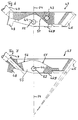
- the rocker leg 43A facing aft with respect to the boat B bears at its extreme end a 90° segment of a toothed bevel gear 45 that meshes with the toothed bevel gear 42 of the drive member 41 in the working position of the rocker Fig 8A.
- the toothed bevel gears 42 and 45 are perfectly engaged when the approximately horizontal underside (stop 46B) of the rocker leg 43A is resting with a stop face 46A on the head 23A of the auxiliary rudder shaft 23 such that the angle between them is minimal. This precisely defines the mechanical play of the toothed bevel gear 42, 45.
- the rocker 43 is transferred to the resting position shown in Figure 8B by pivoting it through approximately 15° about the rocker axis 44 by means of an auxiliary steering tiller 47 that may optionally be capable of being fastened in different positions.
- the underside of the front rocker leg 43B rises to the left, i.e. forwards, in the working position and has a nose-like conical blocking element 48 formed, for example integrally, on its free end. Pivoting the rocker from the working position shown in Figures 1 and 8A into the resting position shown in Figure 8B inserts the blocking element 48 into a conical recess 49, provided on the supporting structure 21, that serves as the blocking counter.
- auxiliary rudder is simultaneously to be held blocked against rotation in its neutral position when the rocker is in the resting position, i.e. in the disengaged state.
- the rocker 43 must assume either the working position or the blocking position; no other states are possible.
- the rocker 43 is configured on its underside for a positive-locking connection with the head of the auxiliary rudder shaft 23 in such a way that two recesses 51 (Fig. 3, 4 and 6) provided parallel to the keel line are incorporated in the underside of the rocker so as to give the longest possible double lever for transmitting the rotatory force.
- the recesses 51 which can be seen most clearly in Figures 3, 4 and 6, are shaped to conform to hump-like elements 26 (Fig. 8A/B) provided at the head of the auxiliary rudder shaft 23 such that these humps are able to engage in the recess 51 with minimum play, but also such that the rocker 43 can be pivoted about these humps between the working position and the resting position.
- the rocker 43 has a bore right through its width along the rocker axis 44 (Fig. 3 and 4) such that swivel pins 53, which can be inserted and screwed fast into the bores 52 from both sides, pass through the recesses 51 such that they coincide with the humps on the head of the auxiliary rudder shaft (Fig. 8A/B).
- these humps are drilled through flush with the bores 52 so that the swivel pins 53 are accommodated to minimize play.
- the rocker 43 is thus fastened such that it cannot be lost, is free to pivot and can rotate together with the auxiliary rudder shaft 23 about the auxiliary rudder shaft axis.
- This retaining element consists of a one-sided lever arm 54, which is fastened in a central position in the head of the auxiliary rudder shaft 23 and can pivot about an approximately horizontal lateral axis 59 ( Figures 1 and 8A/B).
- This lever arm 54 passes through the central region of the rocker 43.
- the rocker 43 has an elongated hole 55 extending approximately parallel to the keel line K with the auxiliary rudder 20 in the neutral position and being arranged such that the rocker axis 44 passes approximately through the centre of the elongated hole 55.
- the swivel pins 53 thus end close to the wall of the elongated hole so that there is space in this region of the elongated hole for the lever arm 54 to pass through.
- Stop surfaces 56 and 57 are provided at the upper opening end of the elongated hole 55 to support a clamping piece 54B, which is mounted on the lever arm 54 such that it can be adjusted along the lever arm 54 using an actuator 58 (Fig. 1).
- the lever arm 54 which is limited in its pivoting movement by the elongated hole 55, is pivoted about its pivoting axis 59 into the rearmost position, to the right in the drawing, in the working position so that the clamping piece rests against the stop surface 57 and holds the rocker 43 in its working position.
- the lever arm 54 As the pivoting axis 59 of the lever arm 54 is positioned with some spacing below the rocker axis 44, the lever arm 54 is always held in a defined position and thus cannot accidentally pivot out of the respective pivoting position if, for example, vibration causes the clamping element to release unintentionally (Fig. 7).
- the lever arm can also serve as a remote control for pivoting the rocker when the clamping element is released.
Landscapes
- Chemical & Material Sciences (AREA)
- Engineering & Computer Science (AREA)
- Combustion & Propulsion (AREA)
- Mechanical Engineering (AREA)
- Ocean & Marine Engineering (AREA)
- Steering-Linkage Mechanisms And Four-Wheel Steering (AREA)
- Toys (AREA)
- Transmission Devices (AREA)
- Mechanical Operated Clutches (AREA)
Applications Claiming Priority (2)
| Application Number | Priority Date | Filing Date | Title |
|---|---|---|---|
| DE29714603U | 1997-08-18 | ||
| DE29714603U DE29714603U1 (de) | 1997-08-18 | 1997-08-18 | Selbststeueranlage für Boote |
Publications (2)
| Publication Number | Publication Date |
|---|---|
| EP0897860A2 true EP0897860A2 (de) | 1999-02-24 |
| EP0897860A3 EP0897860A3 (de) | 2000-11-02 |
Family
ID=8044635
Family Applications (1)
| Application Number | Title | Priority Date | Filing Date |
|---|---|---|---|
| EP98115471A Withdrawn EP0897860A3 (de) | 1997-08-18 | 1998-08-18 | Selbststeuersystem für Boote |
Country Status (6)
| Country | Link |
|---|---|
| US (1) | US6098561A (de) |
| EP (1) | EP0897860A3 (de) |
| AU (1) | AU8078098A (de) |
| CA (1) | CA2245192A1 (de) |
| DE (1) | DE29714603U1 (de) |
| NZ (1) | NZ331439A (de) |
Families Citing this family (2)
| Publication number | Priority date | Publication date | Assignee | Title |
|---|---|---|---|---|
| US6880478B2 (en) * | 2003-07-18 | 2005-04-19 | Lockheed Martin Corporation | Two degree of freedom rudder/stabilizer for waterborne vessels |
| US8483443B2 (en) * | 2008-10-23 | 2013-07-09 | Koninklijke Philips Electronics N.V. | Method for characterizing object movement from CT imaging data |
Citations (2)
| Publication number | Priority date | Publication date | Assignee | Title |
|---|---|---|---|---|
| EP0243942A2 (de) | 1986-04-29 | 1987-11-04 | Peter Förthmann | Hydrodynamische Servosteuerung für Boote |
| DE8810313U1 (de) | 1988-08-13 | 1988-12-08 | IBO-GmbH Vertriebsgesellschaft, 23617 Stockelsdorf | Abfallsack |
Family Cites Families (5)
| Publication number | Priority date | Publication date | Assignee | Title |
|---|---|---|---|---|
| GB1326020A (en) * | 1969-12-31 | 1973-08-08 | Daniels D K | Self-steering gear for marine craft |
| US3983831A (en) * | 1975-06-17 | 1976-10-05 | Stellan P. Knoos | Boat steering device utilizing hydrodynamic servo |
| SE445329B (sv) * | 1984-10-26 | 1986-06-16 | Knoeoes Stellan | Vindroderanordning for en segelbat |
| DE8810315U1 (de) * | 1988-08-14 | 1988-11-17 | Hamburger Laden Arbeits-, Berufs-, Sport- und Seemannskleidung Klara Biniakowski Inh.: Walter Kaminski, 1000 Berlin | Windbetätigte Selbststeuervorrichtung für Segelboote |
| DE8908829U1 (de) * | 1989-07-20 | 1990-11-15 | Hamburger Laden Arbeits-, Berufs-, Sport- und Seemannskleidung Klara Biniakowski Inh.: Walter Kaminski, 1000 Berlin | Windbetätigte Selbststeuervorrichtung für Segelboote |
-
1997
- 1997-08-18 DE DE29714603U patent/DE29714603U1/de not_active Expired - Lifetime
-
1998
- 1998-08-17 CA CA002245192A patent/CA2245192A1/en not_active Abandoned
- 1998-08-18 US US09/136,155 patent/US6098561A/en not_active Expired - Fee Related
- 1998-08-18 AU AU80780/98A patent/AU8078098A/en not_active Abandoned
- 1998-08-18 EP EP98115471A patent/EP0897860A3/de not_active Withdrawn
- 1998-08-18 NZ NZ331439A patent/NZ331439A/xx unknown
Patent Citations (2)
| Publication number | Priority date | Publication date | Assignee | Title |
|---|---|---|---|---|
| EP0243942A2 (de) | 1986-04-29 | 1987-11-04 | Peter Förthmann | Hydrodynamische Servosteuerung für Boote |
| DE8810313U1 (de) | 1988-08-13 | 1988-12-08 | IBO-GmbH Vertriebsgesellschaft, 23617 Stockelsdorf | Abfallsack |
Also Published As
| Publication number | Publication date |
|---|---|
| US6098561A (en) | 2000-08-08 |
| NZ331439A (en) | 2000-01-28 |
| AU8078098A (en) | 1999-02-25 |
| CA2245192A1 (en) | 1999-02-18 |
| DE29714603U1 (de) | 1998-12-17 |
| EP0897860A3 (de) | 2000-11-02 |
Similar Documents
| Publication | Publication Date | Title |
|---|---|---|
| US11097824B1 (en) | Outboard motor having copilot device | |
| US8408955B2 (en) | Mounting for an outboard engine | |
| US11480966B2 (en) | Marine propulsion control system and method | |
| US4726311A (en) | Unit for supporting handle of watercraft | |
| US7207854B1 (en) | Connection system for two or more marine propulsion devices | |
| WO2006056765A1 (en) | Underwater remotely operated vehicle | |
| JPH0376278B2 (de) | ||
| CA2851699C (en) | Mounting assembly for positioning stern-mounted propulsion units with a forward convergence | |
| US6098561A (en) | Self-steering system for boats | |
| CA1151014A (en) | Outboard drive | |
| JP2724626B2 (ja) | 船舶推進システム用の調節システム | |
| JPS6056680B2 (ja) | 水力サーボ機構を使用した船の舵取り装置 | |
| US3810440A (en) | Steering mechanism for sailboats and the like | |
| US10889358B2 (en) | Mounting assembly for positioning stern-mounted propulsion units with a forward convergence | |
| JP2518868B2 (ja) | 船外機の支持装置 | |
| US5246392A (en) | Stern drive system with anti-rotation brace | |
| JP3978183B2 (ja) | 滑りスイベルピストン関節を有する舵 | |
| JPS61278495A (ja) | 舶用機関支持装置 | |
| US3651778A (en) | Coupling apparatus for watercraft | |
| JP2013014159A (ja) | 船舶の舵固定装置及び船舶の舵固定時の操船方法 | |
| US3191203A (en) | Sculling support for an oar | |
| US4919629A (en) | Steering device for marine propulsion | |
| JPS6159959B2 (de) | ||
| JPH0230920B2 (ja) | Hakuyopuroperasochi | |
| JP4688571B2 (ja) | ポッドプロペラ推進器を有する船舶の操船方法 |
Legal Events
| Date | Code | Title | Description |
|---|---|---|---|
| PUAI | Public reference made under article 153(3) epc to a published international application that has entered the european phase |
Free format text: ORIGINAL CODE: 0009012 |
|
| AK | Designated contracting states |
Kind code of ref document: A2 Designated state(s): DE FR GB NL |
|
| AX | Request for extension of the european patent |
Free format text: AL;LT;LV;MK;RO;SI |
|
| PUAL | Search report despatched |
Free format text: ORIGINAL CODE: 0009013 |
|
| AK | Designated contracting states |
Kind code of ref document: A3 Designated state(s): AT BE CH CY DE DK ES FI FR GB GR IE IT LI LU MC NL PT SE |
|
| AX | Request for extension of the european patent |
Free format text: AL;LT;LV;MK;RO;SI |
|
| 17P | Request for examination filed |
Effective date: 20010330 |
|
| AKX | Designation fees paid |
Free format text: DE FR GB NL |
|
| 17Q | First examination report despatched |
Effective date: 20011108 |
|
| STAA | Information on the status of an ep patent application or granted ep patent |
Free format text: STATUS: THE APPLICATION IS DEEMED TO BE WITHDRAWN |
|
| 18D | Application deemed to be withdrawn |
Effective date: 20020619 |