EP0897162A2 - Radio Transponder - Google Patents
Radio Transponder Download PDFInfo
- Publication number
- EP0897162A2 EP0897162A2 EP98306384A EP98306384A EP0897162A2 EP 0897162 A2 EP0897162 A2 EP 0897162A2 EP 98306384 A EP98306384 A EP 98306384A EP 98306384 A EP98306384 A EP 98306384A EP 0897162 A2 EP0897162 A2 EP 0897162A2
- Authority
- EP
- European Patent Office
- Prior art keywords
- transponder
- frequency
- transmitting
- antenna
- coupled
- Prior art date
- Legal status (The legal status is an assumption and is not a legal conclusion. Google has not performed a legal analysis and makes no representation as to the accuracy of the status listed.)
- Granted
Links
Images

Classifications
-
- H—ELECTRICITY
- H01—ELECTRIC ELEMENTS
- H01Q—ANTENNAS, i.e. RADIO AERIALS
- H01Q7/00—Loop antennas with a substantially uniform current distribution around the loop and having a directional radiation pattern in a plane perpendicular to the plane of the loop
-
- G—PHYSICS
- G06—COMPUTING OR CALCULATING; COUNTING
- G06K—GRAPHICAL DATA READING; PRESENTATION OF DATA; RECORD CARRIERS; HANDLING RECORD CARRIERS
- G06K19/00—Record carriers for use with machines and with at least a part designed to carry digital markings
- G06K19/06—Record carriers for use with machines and with at least a part designed to carry digital markings characterised by the kind of the digital marking, e.g. shape, nature, code
- G06K19/067—Record carriers with conductive marks, printed circuits or semiconductor circuit elements, e.g. credit or identity cards also with resonating or responding marks without active components
- G06K19/07—Record carriers with conductive marks, printed circuits or semiconductor circuit elements, e.g. credit or identity cards also with resonating or responding marks without active components with integrated circuit chips
- G06K19/0723—Record carriers with conductive marks, printed circuits or semiconductor circuit elements, e.g. credit or identity cards also with resonating or responding marks without active components with integrated circuit chips the record carrier comprising an arrangement for non-contact communication, e.g. wireless communication circuits on transponder cards, non-contact smart cards or RFIDs
- G06K19/0726—Record carriers with conductive marks, printed circuits or semiconductor circuit elements, e.g. credit or identity cards also with resonating or responding marks without active components with integrated circuit chips the record carrier comprising an arrangement for non-contact communication, e.g. wireless communication circuits on transponder cards, non-contact smart cards or RFIDs the arrangement including a circuit for tuning the resonance frequency of an antenna on the record carrier
-
- G—PHYSICS
- G06—COMPUTING OR CALCULATING; COUNTING
- G06K—GRAPHICAL DATA READING; PRESENTATION OF DATA; RECORD CARRIERS; HANDLING RECORD CARRIERS
- G06K19/00—Record carriers for use with machines and with at least a part designed to carry digital markings
- G06K19/06—Record carriers for use with machines and with at least a part designed to carry digital markings characterised by the kind of the digital marking, e.g. shape, nature, code
- G06K19/067—Record carriers with conductive marks, printed circuits or semiconductor circuit elements, e.g. credit or identity cards also with resonating or responding marks without active components
- G06K19/07—Record carriers with conductive marks, printed circuits or semiconductor circuit elements, e.g. credit or identity cards also with resonating or responding marks without active components with integrated circuit chips
- G06K19/077—Constructional details, e.g. mounting of circuits in the carrier
- G06K19/07749—Constructional details, e.g. mounting of circuits in the carrier the record carrier being capable of non-contact communication, e.g. constructional details of the antenna of a non-contact smart card
- G06K19/07766—Constructional details, e.g. mounting of circuits in the carrier the record carrier being capable of non-contact communication, e.g. constructional details of the antenna of a non-contact smart card comprising at least a second communication arrangement in addition to a first non-contact communication arrangement
- G06K19/07767—Constructional details, e.g. mounting of circuits in the carrier the record carrier being capable of non-contact communication, e.g. constructional details of the antenna of a non-contact smart card comprising at least a second communication arrangement in addition to a first non-contact communication arrangement the first and second communication means being two different antennas types, e.g. dipole and coil type, or two antennas of the same kind but operating at different frequencies
-
- H—ELECTRICITY
- H01—ELECTRIC ELEMENTS
- H01Q—ANTENNAS, i.e. RADIO AERIALS
- H01Q1/00—Details of, or arrangements associated with, antennas
- H01Q1/12—Supports; Mounting means
- H01Q1/22—Supports; Mounting means by structural association with other equipment or articles
- H01Q1/2208—Supports; Mounting means by structural association with other equipment or articles associated with components used in interrogation type services, i.e. in systems for information exchange between an interrogator/reader and a tag/transponder, e.g. in Radio Frequency Identification [RFID] systems
- H01Q1/2225—Supports; Mounting means by structural association with other equipment or articles associated with components used in interrogation type services, i.e. in systems for information exchange between an interrogator/reader and a tag/transponder, e.g. in Radio Frequency Identification [RFID] systems used in active tags, i.e. provided with its own power source or in passive tags, i.e. deriving power from RF signal
-
- H—ELECTRICITY
- H01—ELECTRIC ELEMENTS
- H01Q—ANTENNAS, i.e. RADIO AERIALS
- H01Q21/00—Antenna arrays or systems
- H01Q21/28—Combinations of substantially independent non-interacting antenna units or systems
Definitions
- the present invention relates to a transponder and more specifically to a transponder which re-radiates a modulated signal on a transponder frequency derived from a carrier frequency received on a transponder antenna.
- the present invention is advantageously applied to the construction and operation of a radio frequency identification (RFID) tag such as that disclosed in commonly owned U.S. Patent No. 5,530,702 of Palmer et al. ("the '702 Patent”), and to an article-identifying transmitter in a checkout or inventory control system such as described in commonly owned U.S. Patent No. 5,239,167 to Kipp ("the '167 Patent”).
- RFID radio frequency identification
- the '167 Patent discloses a system for detecting multiple randomly disposed articles without moving or contacting the articles. As described in the '167 Patent, an actuator signals transmitters (RFID tags) attached to each article to begin operating. Each transmitter then transmits a signal identifying the article in turn and then deactuates itself.
- RFID tags RFID tags
- RFID tags must be inexpensive to manufacture, because they are applied to merchandise articles with no requirement or expectation of being returned by the customer.
- the RFID tag must be capable of reliably transmitting a multiple digit identifying signal, and must operate in such manner that its transmissions will be received despite that many other RFID tags will also be operating and transmitting identifying signals.
- RFID tags transmit and receive signals to and from an interrogator transceiver (hereinafter, “the interrogator") over relatively short distances on the scale of a few meters or less.
- the interrogator Frequency modulation
- FM Frequency modulation
- AM amplitude modulation
- the range-limiting constraint becomes the sensitivity of the receiving circuitry of the RFID tag.
- the inventors have found that a transponder implementation in which the RFID tag transmits by re-radiating a carrier frequency derived from a received carrier frequency further helps to satisfy both transmission performance and cost considerations.
- the RFID tag transponder transmits on a transmitting frequency which is derived from, but different from the frequency of a carrier signal which is broadcasted by the interrogator.
- a transmitting frequency which is derived from, but different from the frequency of a carrier signal which is broadcasted by the interrogator.
- the provision of a local oscillator and mixer in the transmitting circuitry of the transponder would be expected to increase the noise rejection for signals transmitted by the transponder.
- the inventors have found that the added cost of such circuitry would provide no advantage because the range-limiting constraint remains the sensitivity of the receiver portion of the transponder.
- U.S. Patent No. 3,944,928 describes a harmonic communication system.
- a transponder receives a fundamental carrier frequency, generates a harmonic frequency therefrom, and modulates the harmonic frequency with a pulse-width modulating signal provided by a code storage 40 contained on the transponder.
- U.S. Patent No. 4,656,478 describes a transponder having an antenna 12 which is tuned to a broadcasted frequency f0 and a diode 19 which generates a second harmonic frequency 2xf0 therefrom for re-radiation on tuned antenna lobes 14a and 14b.
- U.S. Patent No. 4,979,232 describes a solid state switch which permits both a transmitter 45 and a receiver 55 to share a common antenna. As described in the '232 Patent, reverse bias is applied to a diode 15 to present high impedance to block damaging currents generated by transmitter 45 from reaching receiver 55.
- none of the '928 Patent, the '478 Patent, or the '232 Patent describe a system by which a transponder suppresses the undesired emission of harmonic frequencies while not transmitting.
- U.S. Patent No. 4,059,801 describes a "de-Q-ing" circuit used to lower the Q factor of a transmitting antenna during quiescent intervals between transmissions.
- the '801 Patent does not describe a system which affirmatively detunes an antenna to a different frequency to prevent a broadcasted frequency from being received thereon during non-transmitting intervals.
- the radio frequency transponder of the present invention transmits information signals by modulating a harmonic frequency derived from a fundamental carrier frequency broadcasted by the interrogator.
- the transponder of the present invention is constructed to meet the following objectives. First, the transponder generates a harmonic carrier frequency from an incoming broadcasted carrier frequency, modulates that harmonic carrier frequency with a multiple digit information signal, and transmits the modulated harmonic carrier signal for reception by the interrogator with a sufficient signal-to-noise ratio to permit the received data to be reliably discriminated.
- the transponder since the transponder operates within a communication system which performs checkout or inventory control, multiple RFID tag transponders receive signals on a carrier frequency broadcasted by the interrogator while only just one transponder transmits a signal at a particular time. Accordingly, the transponder disclosed herein contains specific circuitry in receiver and transmitter portions thereof which suppress undesirable emissions of the harmonic transmitting frequency when the transponder is not transmitting a signal.
- FIG. 1 is a block diagram showing the circuitry of the transponder of the present invention.
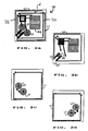
- FIG. 2a is a diagram showing a physical implementation of the transponder of the present invention.
- FIG. 2b is a diagram showing a front plan view of a front side of a physical implementation of the transponder.
- FIG. 2c is a diagram showing a front plan view of a rear side of a physical implementation of the transponder.
- FIG. 2d is a diagram showing a rear plan view of a rear side of a physical implementation of the transponder.
- FIG. 1 shows a schematic circuit diagram of the radio transponder of the present invention.
- transponder 10 includes a controller/information store 12, preferably implemented in an integrated circuit (U1) having memory and control logic, a battery B1, receiving circuitry 16, and transmitting circuitry 18.
- U1 integrated circuit
- Receiving circuitry 16 includes receiving antenna L1, a demodulator 20, and a terminating circuit 22.
- Demodulator 20 is preferably constructed as an envelope detector including a diode D1, capacitor C1, and resistor R1 having values appropriately matched to the carrier frequency f0 at which signals are transmitted to the transponder by the interrogator.
- the demodulated output of demodulator 20 is provided, preferably at baseband, to controller/information store 12 through terminal DIN.
- Terminating circuit 22 suppresses the re-radiation by receiving antenna L1 of signal energy at the second harmonic frequency, i.e. 2xf0, and other even harmonics of the carrier frequency f0 transmitted by the interrogator. Because the second harmonic frequency is the transponder transmitting frequency, terminating circuit 22 is not specifically aimed at reducing, nor is required to reduce the emission of signal energy at odd harmonicas of the fundamental carrier frequency. Terminating circuit 22 includes elements which form a circuit which operates in an anti-symmetrical manner with respect to demodulator 20. Thus, in the preferred embodiment shown in FIG.
- terminating circuit has elements including diode D2, capacitor C5 and resistor R6 forming a 'negative image' of the demodulator 20 formed by diode D1, capacitor C1, and resistor R1 and which operates to prevent modulation products at even harmonics of the fundamental carrier frequency from being introduced by demodulator 20 onto antenna L1 and being re-radiated.
- Transmitting circuitry 18 has several functions: 1) to generate a transponder transmitting frequency as a harmonic of the carrier frequency transmitted by the interrogator; 2) to modulate an information signal onto that transmitting frequency for transmission to the interrogator; 3) to transmit the modulated information signal by re-radiating the transmitting frequency; and 4) while not transmitting, to suppress the undesired emission of the transmitting frequency.
- Transmitting circuitry 18 includes transmitting antenna L4; a pair of capacitors C6 and C7; respective RLC circuits formed by: resistor R7, inductor L2, and capacitor C8; and resistor R8, inductor L3, and capacitor C9; and harmonic frequency generator and modulator 24.
- RLC circuits are matched with respect to each other in impedance and amplitude-frequency characteristics.
- Harmonic frequency generator and modulator 24 preferably includes a diode D3 and is coupled to transmitting antenna L4 through capacitors C6 and C7.
- Transmitting circuitry 18 is coupled to complementary outputs DOUT and DOUT* of controller/information store 12 through respective RLC circuits.
- RLC circuits 26 and 28 and coupling capacitors C6 and C7 have impedance and frequency characteristics such that when diode D3 is forward biased, transmitting antenna L4 is resonance tuned to the fundamental carrier frequency f0 transmitted by the interrogator. However, when diode D3 is reverse biased, current flow is prevented through diode D3, thereby causing antenna L4 to effectively become resonance tuned to twice the fundamental frequency, i.e. to the second harmonic 2xf0.
- transmitting antenna L4 is resonance tuned to the second harmonic frequency, i.e. 2xf0.
- antenna L4 only poorly receives energy of the fundamental carrier frequency f0 broadcasted by the interrogator, with the result that re-radiation of the fundamental carrier frequency and its harmonics are suppressed on transmitting antenna L4.
- FIGS. 2a-2d show respective views of a conductor pattern for a physical embodiment of the present invention.
- FIG. 2a shows conductor patterns for both front and rear patterned surfaces of a low profile transponder which is adapted to be attached to a surface of a merchandise article.
- inductors L2 and L3 are implemented in spiralled conductor patterns positioned on the rear side of transponder 10 (FIG. 2c), opposite the front side upon which transmitting antenna L4 is positioned.
- integrated circuit U1 which implements controller/information store 12, battery B1, inductors L2 and L3 and receiving antenna L1 are connected by conductor patterns positioned on the front side of the transponder 10. It will be appreciated that integrated circuit U1, battery B1, and the connecting conductor patterns need not be placed on any particular side of transponder 10, and that it may be desirable in some circumstances to connect these elements with conductor patterns formed on both sides of transponder 10.
- Antennas L1 and L4 are formed of conductors having roughly square loop patterns on respective front and rear sides of transponder 10.
- a loop shape was selected for antennas L1 and L4 because such shape reduces the influence of directional orientation on transmitting and receiving efficiency. This consideration is important for the intended communication system in which randomly oriented transponders must be capable of efficient communication with the interrogator.
- the transmitting and receiving antennas L4 and L1 must be so positioned that transmitting signal energy present on transmitting antenna L4 not be absorbed excessively by receiving antenna L1 to prevent its transmission to the interrogator.
- the transponder In determining the placement of antennas L1 and L4, a further constraint exists in that the transponder must be contained in a small and unobtrusive package which can be utilized in a checkout or inventory monitoring system. Efficient utilization of the total surface area of the transponder is achieved when conductor patterns are placed on both front and rear sides of the package.
- conductor patterns forming antennas L1 and L4 are placed on respective opposite sides of the transponder and are offset from each other such that neither antenna vertically overlays the other over any substantial unit of length and antennas L1 and L4 are separated from each other by a minimum separation of 3mm when the width of the conductor patterns forming antennas L1 and L4 is 1.5mm.
- Diode D3 which functions as harmonic generator and modulator 24 has cathode and anode terminals coupled to conductors 30, 32, which form a loop antenna L4 used for transmitting.
- diode D3 When diode D3 is forward biased by respective high and low level voltages on complementary outputs DOUT and DOUT*, current flows through diode D3 over the combined length of conductors 30 and 32 which form transmitting antenna L4.
- diode D3 is reverse biased by respective low and high level voltages on complementary outputs DOUT and DOUT* diode D3 blocks the flow of current between conductors 30, 32.
- antenna L4 resonates at the fundamental carrier frequency f0 of the interrogator. If diode D3 is positioned at the midpoint of antenna L4 such that each conductor 30, 32 is approximately half the full length of antenna L4, it will be appreciated each conductor 30, 32, when operated as a separate antenna, will resonate at twice the fundamental carrier frequency, i.e. 2xf0. Accordingly, when reverse bias is applied to diode D3, antenna L4 resonates at the second harmonic frequency.
- Communication begins by the interrogator broadcasting a BEGIN signal on a fundamental carrier frequency to all the transponders which are located within a defined area such as an checkout system or an defined inventory area.
- the BEGIN signal is received by each transponder 10 on receiving antenna L1 and demodulated by demodulator 20 to provide input, preferably at baseband, through DIN terminal to controller/information store 12.
- Receipt of the demodulated BEGIN signal by controller/ information store 12 causes transponder 10 to switch from a quiesced state requiring only minimal power from battery B1 to a fully operational initialized state, at which time a counter included in controller/information store 12 (as shown in the '702 Patent) begins counting up or down towards a time to transmit, which time is preferably determined pseudo-randomly for each transponder.
- controller/information store 12 While transponder 10 counts towards its time to transmit, controller/information store 12 maintains reverse bias on diode D3 (by holding DOUT and DOUT* outputs at respective low and high level voltages) to cause transmitting antenna L4 to be detuned from the fundamental carrier frequency transmitted by the interrogator. In this way, transponder 10 suppresses the emission of energy at the transmitting frequency on transmitting antenna L4.
- controller/information store 12 switches the polarities of complementary outputs DOUT and DOUT* in a controlled, timed sequence to provide a modulating information signal to transmitting circuitry 18.
- the modulating information signal applies forward and reverse bias to diode D3 in a controlled, timed sequence to cause diode D3 to generate corresponding timed pulses of energy at harmonics of the fundamental carrier frequency, which pulses are coupled back onto transmitting antenna L4 for transmission to the interrogator.
- controller/information store 12 switches the complementary outputs DOUT and DOUT* in such manner to produce a pulse-width modulating (PWM) signal.
- PWM pulse-width modulating
- the inventors have found that a lower bit error rate can be obtained for the same signal energy when pulse width modulation transmission is utilized than with pulse amplitude modulation.
- PWM signals can be more easily and accurately clocked at the receiver. For the same reasons, PWM transmission is preferred for signals transmitted by the interrogator to transponders 10.
- a logic "0" pulse is represented scheme by holding the DOUT and DOUT* outputs at respective high and low level voltages over a short duty cycle (preferably about 25%) during each data bit interval
- a logic "1" pulse is represented by holding the DOUT and DOUT* outputs at respective high and low level voltages over a longer duty cycle (preferably about 75%) during each data bit interval.
- the transponder 10 when the counter in an RFID tag transponder 10 reaches the pseudo-randomly determined time to transmit, the transponder 10 transmits a request to transmit signal, and then waits for acknowledgement from the interrogator before proceeding to transmit an article-identifying signal.
- the RFID tag transponder disclosed herein must be capable of receiving and responding to signals which are transmitted by the interrogator at different times during communication.
- receiving circuitry 16 receives and demodulates all signals which are transmitted on the fundamental carrier frequency f0, although such operation is not specifically required. Controller/information store 12 ignores all such received signals except when it is determined that the received signal relates to the particular transponder 10. Terminating circuit 22, being matched in characteristic to the transponder transmitting frequency (i.e. 2xf0), suppresses unwanted emissions of that transmitting frequency that would otherwise result because of demodulator 20 remaining coupled to receiving antenna L1.
- the transponder of the present invention provides for more efficient and reliable communication of digital information on a single re-radiated transmitting frequency by suppressing the undesirable emission of that transmitting frequency from its own transmitting and receiving circuitry.
Landscapes
- Engineering & Computer Science (AREA)
- Computer Hardware Design (AREA)
- Microelectronics & Electronic Packaging (AREA)
- Physics & Mathematics (AREA)
- General Physics & Mathematics (AREA)
- Theoretical Computer Science (AREA)
- Computer Networks & Wireless Communication (AREA)
- Radar Systems Or Details Thereof (AREA)
- Near-Field Transmission Systems (AREA)
Priority Applications (2)
| Application Number | Priority Date | Filing Date | Title |
|---|---|---|---|
| EP07022931A EP1898343A3 (de) | 1997-08-13 | 1998-08-10 | Funktransponder |
| EP07022930A EP1898342A3 (de) | 1997-08-13 | 1998-08-10 | Funktransponder |
Applications Claiming Priority (2)
| Application Number | Priority Date | Filing Date | Title |
|---|---|---|---|
| US08/910,293 US5942977A (en) | 1997-08-13 | 1997-08-13 | Radio transponder |
| US910293 | 1997-08-13 |
Related Child Applications (2)
| Application Number | Title | Priority Date | Filing Date |
|---|---|---|---|
| EP07022930A Division EP1898342A3 (de) | 1997-08-13 | 1998-08-10 | Funktransponder |
| EP07022931A Division EP1898343A3 (de) | 1997-08-13 | 1998-08-10 | Funktransponder |
Publications (3)
| Publication Number | Publication Date |
|---|---|
| EP0897162A2 true EP0897162A2 (de) | 1999-02-17 |
| EP0897162A3 EP0897162A3 (de) | 1999-07-28 |
| EP0897162B1 EP0897162B1 (de) | 2007-11-28 |
Family
ID=25428579
Family Applications (3)
| Application Number | Title | Priority Date | Filing Date |
|---|---|---|---|
| EP07022930A Withdrawn EP1898342A3 (de) | 1997-08-13 | 1998-08-10 | Funktransponder |
| EP98306384A Expired - Lifetime EP0897162B1 (de) | 1997-08-13 | 1998-08-10 | Radio Transponder |
| EP07022931A Withdrawn EP1898343A3 (de) | 1997-08-13 | 1998-08-10 | Funktransponder |
Family Applications Before (1)
| Application Number | Title | Priority Date | Filing Date |
|---|---|---|---|
| EP07022930A Withdrawn EP1898342A3 (de) | 1997-08-13 | 1998-08-10 | Funktransponder |
Family Applications After (1)
| Application Number | Title | Priority Date | Filing Date |
|---|---|---|---|
| EP07022931A Withdrawn EP1898343A3 (de) | 1997-08-13 | 1998-08-10 | Funktransponder |
Country Status (4)
| Country | Link |
|---|---|
| US (1) | US5942977A (de) |
| EP (3) | EP1898342A3 (de) |
| CA (1) | CA2245005A1 (de) |
| DE (1) | DE69838774T2 (de) |
Cited By (2)
| Publication number | Priority date | Publication date | Assignee | Title |
|---|---|---|---|---|
| EP1251458A3 (de) * | 2001-04-19 | 2003-01-02 | Matsushita Electric Industrial Co., Ltd. | Integrierte Halbleiterschaltung |
| JP2005293597A (ja) * | 2005-04-05 | 2005-10-20 | Matsushita Electric Ind Co Ltd | 半導体集積回路とこれを搭載した非接触型情報媒体 |
Families Citing this family (45)
| Publication number | Priority date | Publication date | Assignee | Title |
|---|---|---|---|---|
| US6445296B1 (en) * | 1996-08-21 | 2002-09-03 | A.T.L. Agricultural Technology Limited | Identification apparatus |
| US6356535B1 (en) * | 1998-02-04 | 2002-03-12 | Micron Technology, Inc. | Communication systems and methods of communicating |
| GB9813371D0 (en) * | 1998-06-22 | 1998-08-19 | Powell George L | Anti-collision tag apparatus and system |
| US7710273B2 (en) * | 1999-09-02 | 2010-05-04 | Round Rock Research, Llc | Remote communication devices, radio frequency identification devices, wireless communication systems, wireless communication methods, radio frequency identification device communication methods, and methods of forming a remote communication device |
| US6294997B1 (en) * | 1999-10-04 | 2001-09-25 | Intermec Ip Corp. | RFID tag having timing and environment modules |
| US6373389B1 (en) * | 2000-04-21 | 2002-04-16 | Usm Systems, Ltd. | Event driven information system |
| DE10104377A1 (de) * | 2001-02-01 | 2002-08-08 | Reitter & Schefenacker Gmbh | Betätigungsvorrichtung für Entriegelungseinrichtungen von Fahrzeugen, vorzugsweise von Kraftfahrzeugen |
| EP1454294B1 (de) * | 2001-11-21 | 2006-06-07 | Mineral Lassen LLC | Drahtgebundene schnittstelle zu einem drahtlosen kommunikationsgerät |
| US6614392B2 (en) * | 2001-12-07 | 2003-09-02 | Delaware Capital Formation, Inc. | Combination RFID and GPS functionality on intelligent label |
| US20030135817A1 (en) * | 2002-01-11 | 2003-07-17 | G.E. Information Services, Inc. | Automated method, system and software for storing data in a general format in a global network |
| US6856250B2 (en) | 2002-01-11 | 2005-02-15 | Randy Hilliard | Tracking system, apparatus and method |
| DE60300748T2 (de) * | 2002-05-09 | 2006-05-11 | Kel Corp., Tama | Pulsübertragungsmodulations- und -demodulationsverfahren |
| US6853303B2 (en) | 2002-11-21 | 2005-02-08 | Kimberly-Clark Worldwide, Inc. | RFID system and method for ensuring personnel safety |
| US7490054B2 (en) * | 2002-11-21 | 2009-02-10 | Kimberly-Clark Worldwide, Inc. | RFID system and method for vending machine control |
| US6982640B2 (en) * | 2002-11-21 | 2006-01-03 | Kimberly-Clark Worldwide, Inc. | RFID system and method for tracking food freshness |
| US20040103034A1 (en) * | 2002-11-21 | 2004-05-27 | Kimberly-Clark Worldwide, Inc. | RFID system and method for purchase item accountability |
| US7061379B2 (en) * | 2002-11-21 | 2006-06-13 | Kimberly-Clark Worldwide, Inc. | RFID system and method for ensuring safety of hazardous or dangerous substances |
| US7617132B2 (en) * | 2002-11-21 | 2009-11-10 | Kimberly-Clark Worldwide, Inc. | RFID system and method for ensuring food safety |
| US6940467B2 (en) * | 2003-01-10 | 2005-09-06 | Atmel Germany Gmbh | Circuit arrangement and method for deriving electrical power from an electromagnetic field |
| US7369609B2 (en) * | 2003-04-01 | 2008-05-06 | The Boeing Company | Duty factor encoded data and clock transmission |
| US20050149414A1 (en) * | 2003-12-30 | 2005-07-07 | Kimberly-Clark Worldwide, Inc. | RFID system and method for managing out-of-stock items |
| US7853477B2 (en) * | 2003-12-30 | 2010-12-14 | O'shea Michael D | RF-based electronic system and method for automatic cross-marketing promotional offers and check-outs |
| US7463142B2 (en) | 2003-12-30 | 2008-12-09 | Kimberly-Clark Worldwide, Inc. | RFID system and method for tracking environmental data |
| US7034687B2 (en) * | 2004-04-29 | 2006-04-25 | Comm-Engines | Error-avoiding anti-theft surveillance system |
| US20060263837A1 (en) * | 2004-06-17 | 2006-11-23 | Liu George D | Immunoassay system and method for detection of antigens |
| US7683789B2 (en) * | 2005-03-04 | 2010-03-23 | Intelleflex Corporation | Compact omni-directional RF system |
| KR100721057B1 (ko) * | 2005-11-03 | 2007-05-22 | 한국전자통신연구원 | 무선주파수 식별 태그를 위한 전압체배기 |
| US7884725B2 (en) | 2006-06-21 | 2011-02-08 | Neology, Inc. | Systems and methods for stirring electromagnetic fields and interrogating stationary RFID tags |
| US9489813B1 (en) * | 2006-09-22 | 2016-11-08 | Michael L. Beigel | System for location in environment and identification tag |
| JP4977438B2 (ja) * | 2006-10-25 | 2012-07-18 | 日本電気株式会社 | 通信装置及びそれを用いた携帯通信端末 |
| US20080198019A1 (en) * | 2007-02-20 | 2008-08-21 | James Neil Rodgers | RFID antenna and amplification |
| US20090015407A1 (en) * | 2007-07-13 | 2009-01-15 | Micron Technology, Inc. | Rifid tags and methods of designing rfid tags |
| US7777630B2 (en) * | 2007-07-26 | 2010-08-17 | Round Rock Research, Llc | Methods and systems of RFID tags using RFID circuits and antennas having unmatched frequency ranges |
| US9019167B2 (en) | 2008-03-20 | 2015-04-28 | Quotainne Enterprises Llc | Transceiving circuit for contactless communication and NFC device or RFID reader/writer device comprising such a transceiving circuit |
| US8179232B2 (en) * | 2008-05-05 | 2012-05-15 | Round Rock Research, Llc | RFID interrogator with adjustable signal characteristics |
| US7852221B2 (en) * | 2008-05-08 | 2010-12-14 | Round Rock Research, Llc | RFID devices using RFID circuits and antennas having unmatched frequency ranges |
| US8712334B2 (en) | 2008-05-20 | 2014-04-29 | Micron Technology, Inc. | RFID device using single antenna for multiple resonant frequency ranges |
| WO2010018546A1 (en) * | 2008-08-13 | 2010-02-18 | Ipico Innovation Inc | A dual frequency rfid tag |
| EP2511856A1 (de) * | 2011-04-15 | 2012-10-17 | Gemalto SA | Verfahren, Schaltkreis und Vorrichtung zur kontaktlosen Kommunikation über aktivierte Übertragung |
| EP2511977A1 (de) * | 2011-04-15 | 2012-10-17 | Gemalto SA | Anordnung von Sende- und Empfängerantennen eines elektromagnetischen Felds |
| KR101617311B1 (ko) * | 2011-04-15 | 2016-05-02 | 제말토 에스에이 | 활성화된 송신을 이용하는 무접촉 통신을 위한 방법, 회로 및 장치 |
| CN103198283A (zh) * | 2013-04-23 | 2013-07-10 | 复旦大学 | 一种谐波射频识别系统 |
| CN108418592B (zh) * | 2018-01-30 | 2020-05-08 | Oppo广东移动通信有限公司 | 控制辐射杂散的方法及相关设备 |
| CN116964649B (zh) | 2020-12-16 | 2026-02-17 | 新鲜混合物有限公司 | 用于分配及杯内混合饮料平台的智能库存管理系统 |
| DE102023201725A1 (de) | 2023-02-24 | 2024-08-29 | Fraunhofer-Gesellschaft zur Förderung der angewandten Forschung eingetragener Verein | Transceiver und zugehöriges Betriebsverfahren |
Family Cites Families (30)
| Publication number | Priority date | Publication date | Assignee | Title |
|---|---|---|---|---|
| NO126975B (de) * | 1967-03-30 | 1973-04-16 | John Welsh | |
| AU1250170A (en) * | 1970-03-12 | 1971-09-16 | Unisearch Limited | Electronic surveillance system |
| US3689885A (en) * | 1970-09-15 | 1972-09-05 | Transitag Corp | Inductively coupled passive responder and interrogator unit having multidimension electromagnetic field capabilities |
| US3944928A (en) | 1974-07-01 | 1976-03-16 | Microlab/Fxr | Harmonic communication system |
| SE384958B (sv) * | 1974-07-19 | 1976-05-24 | Philips Svenska Ab | Sett for overforing av information i en transponderanleggning samt anordning for utforande av settet |
| US4059801A (en) | 1975-12-11 | 1977-11-22 | Johannessen Paul R | Apparatus for degrading Q in a high-Q RF pulse transmitting system and the like |
| US4068232A (en) * | 1976-02-12 | 1978-01-10 | Fairchild Industries, Inc. | Passive encoding microwave transponder |
| GB1577920A (en) * | 1976-11-01 | 1980-10-29 | Nedap Nv | Detection plate for identification systems |
| GB1599120A (en) * | 1978-05-19 | 1981-09-30 | Philips Electronic Associated | Detection system |
| US4656478A (en) | 1984-07-30 | 1987-04-07 | Asulab S.A. | Passive transponder for locating avalanche victims |
| NL8701565A (nl) * | 1987-07-03 | 1989-02-01 | Nedap Nv | Identificatiesysteem met twee werkingsmodes. |
| FR2640830B1 (fr) * | 1988-12-16 | 1994-08-26 | Levionnais Philippe | Dispositif pour l'echange d'informations a distance entre un objet portatif et une station |
| US4979232A (en) | 1989-08-14 | 1990-12-18 | Harris Corporation | Self-biasing solid-state T/R switch |
| JPH0772907B2 (ja) * | 1989-12-21 | 1995-08-02 | 三菱電機株式会社 | マイクロコンピュータ及びこれを用いた非接触icカード |
| US5287113A (en) * | 1990-02-12 | 1994-02-15 | Texas Instruments Deutschland Gmbh | Voltage limiting batteryless transponder circuit |
| JP2569194B2 (ja) * | 1990-03-13 | 1997-01-08 | 三菱電機株式会社 | マイクロコンピュータ及びこれを用いた非接触icカード |
| US5146193A (en) * | 1991-02-25 | 1992-09-08 | Motorola, Inc. | Monolithic ceramic filter or duplexer having surface mount corrections and transmission zeroes |
| US5239686A (en) * | 1991-04-29 | 1993-08-24 | Echelon Corporation | Transceiver with rapid mode switching capability |
| US5239167A (en) | 1991-04-30 | 1993-08-24 | Ludwig Kipp | Checkout system |
| US5254997A (en) * | 1992-07-31 | 1993-10-19 | Westinghouse Electric Corp. | Retrodirective interrogation responsive system |
| US5541604A (en) * | 1993-09-03 | 1996-07-30 | Texas Instruments Deutschland Gmbh | Transponders, Interrogators, systems and methods for elimination of interrogator synchronization requirement |
| US5450086A (en) * | 1993-12-03 | 1995-09-12 | Texas Instruments Deutschland Gmbh | Self-tuning receiver/decoder for frequency shift keying RF data transmission |
| JP3305843B2 (ja) * | 1993-12-20 | 2002-07-24 | 株式会社東芝 | 半導体装置 |
| US5530702A (en) * | 1994-05-31 | 1996-06-25 | Ludwig Kipp | System for storage and communication of information |
| US5504485A (en) * | 1994-07-21 | 1996-04-02 | Amtech Corporation | System for preventing reading of undesired RF signals |
| WO1996003713A1 (en) * | 1994-07-28 | 1996-02-08 | Westinghouse Electric Corporation | Security access circuit using embedded antennas |
| US5512878A (en) * | 1994-10-06 | 1996-04-30 | Sensormatic Electronics Corporation | Pulsed electronic article surveillance systems |
| US5598169A (en) * | 1995-03-24 | 1997-01-28 | Lucent Technologies Inc. | Detector and modulator circuits for passive microwave links |
| US5680106A (en) * | 1995-10-27 | 1997-10-21 | International Business Machines Corporation | Multibit tag with stepwise variable frequencies |
| FR2746756B1 (fr) * | 1996-04-01 | 1998-06-12 | Matra Transport International | Dispositif de detection de passage d'un mobile, tolerant aux pannes |
-
1997
- 1997-08-13 US US08/910,293 patent/US5942977A/en not_active Expired - Lifetime
-
1998
- 1998-08-10 EP EP07022930A patent/EP1898342A3/de not_active Withdrawn
- 1998-08-10 EP EP98306384A patent/EP0897162B1/de not_active Expired - Lifetime
- 1998-08-10 DE DE69838774T patent/DE69838774T2/de not_active Expired - Lifetime
- 1998-08-10 EP EP07022931A patent/EP1898343A3/de not_active Withdrawn
- 1998-08-13 CA CA002245005A patent/CA2245005A1/en not_active Abandoned
Cited By (3)
| Publication number | Priority date | Publication date | Assignee | Title |
|---|---|---|---|---|
| EP1251458A3 (de) * | 2001-04-19 | 2003-01-02 | Matsushita Electric Industrial Co., Ltd. | Integrierte Halbleiterschaltung |
| US6848620B2 (en) | 2001-04-19 | 2005-02-01 | Matsushita Electric Industrial Co., Ltd. | Semiconductor integrated circuit |
| JP2005293597A (ja) * | 2005-04-05 | 2005-10-20 | Matsushita Electric Ind Co Ltd | 半導体集積回路とこれを搭載した非接触型情報媒体 |
Also Published As
| Publication number | Publication date |
|---|---|
| EP0897162B1 (de) | 2007-11-28 |
| EP1898342A2 (de) | 2008-03-12 |
| US5942977A (en) | 1999-08-24 |
| EP1898342A3 (de) | 2008-05-14 |
| DE69838774D1 (de) | 2008-01-10 |
| EP1898343A3 (de) | 2008-05-14 |
| CA2245005A1 (en) | 1999-02-13 |
| EP0897162A3 (de) | 1999-07-28 |
| EP1898343A2 (de) | 2008-03-12 |
| DE69838774T2 (de) | 2008-10-30 |
Similar Documents
| Publication | Publication Date | Title |
|---|---|---|
| US5942977A (en) | Radio transponder | |
| US7528725B2 (en) | Passive dynamic antenna tuning circuit for a radio frequency identification reader | |
| US8493185B2 (en) | Radio frequency identification reader antenna having a dynamically adjustable Q-factor | |
| US10929620B2 (en) | Harmonic RFID tag-reader system for long range sensing identification and security | |
| EP1323210B1 (de) | Mehrbandiges, drahtloses kommunikationsgerät | |
| EP0324564B1 (de) | System zur Übertragung der Identifikationsinformation und ähnlicher Daten | |
| US20060273882A1 (en) | RFID tag with separate transmit and receive clocks and related method | |
| US6946989B2 (en) | Transponder, including transponder system | |
| AU2005227368B2 (en) | Transponder, including transponder system | |
| JP3646472B2 (ja) | 非接触型icカードおよび送受信回路 | |
| US7504952B2 (en) | Wide band RFID system with tag on flexible label | |
| US20070279192A1 (en) | RFID communication control method and RFID system using same | |
| EP0704928A3 (de) | HF Transpondersystem mit Parallelresonanz-Abfrage und Serienresonanz-Antwort | |
| WO2005020444A2 (en) | System and method for optimizing power usage in a radio frequency communication device | |
| CN113283259B (zh) | 一种基于rfid的多标签射频识别系统及方法 | |
| GB2316274A (en) | Interrogator for semi-passive transponder tags | |
| EP1519306B1 (de) | Speicheretikett und Leser | |
| US20070096874A1 (en) | Distributed RFID interrogation system and method of operating the same | |
| US7570920B2 (en) | AM-FM hybrid signal communicated to RFID tags | |
| JP4850025B2 (ja) | 通信装置 | |
| WO2006047701A2 (en) | Distributed rfid interrogation system and method of operating the same | |
| JPS62277580A (ja) | 識別装置 | |
| JP3065470B2 (ja) | 超再生復調回路をもつ無線受信機 | |
| JPH07240699A (ja) | 近距離マイクロ波識別システム | |
| CN110276222A (zh) | 一种射频识别天线装置 |
Legal Events
| Date | Code | Title | Description |
|---|---|---|---|
| PUAI | Public reference made under article 153(3) epc to a published international application that has entered the european phase |
Free format text: ORIGINAL CODE: 0009012 |
|
| AK | Designated contracting states |
Kind code of ref document: A2 Designated state(s): DE FR GB IT NL |
|
| AX | Request for extension of the european patent |
Free format text: AL;LT;LV;MK;RO;SI |
|
| PUAL | Search report despatched |
Free format text: ORIGINAL CODE: 0009013 |
|
| AK | Designated contracting states |
Kind code of ref document: A3 Designated state(s): AT BE CH CY DE DK ES FI FR GB GR IE IT LI LU MC NL PT SE |
|
| AX | Request for extension of the european patent |
Free format text: AL;LT;LV;MK;RO;SI |
|
| 17P | Request for examination filed |
Effective date: 19991226 |
|
| AKX | Designation fees paid |
Free format text: DE FR GB IT NL |
|
| 17Q | First examination report despatched |
Effective date: 20050131 |
|
| RAP1 | Party data changed (applicant data changed or rights of an application transferred) |
Owner name: MOBILE TECHNICS LLC |
|
| GRAP | Despatch of communication of intention to grant a patent |
Free format text: ORIGINAL CODE: EPIDOSNIGR1 |
|
| GRAS | Grant fee paid |
Free format text: ORIGINAL CODE: EPIDOSNIGR3 |
|
| GRAA | (expected) grant |
Free format text: ORIGINAL CODE: 0009210 |
|
| AK | Designated contracting states |
Kind code of ref document: B1 Designated state(s): DE FR GB IT NL |
|
| REG | Reference to a national code |
Ref country code: GB Ref legal event code: FG4D |
|
| REF | Corresponds to: |
Ref document number: 69838774 Country of ref document: DE Date of ref document: 20080110 Kind code of ref document: P |
|
| PG25 | Lapsed in a contracting state [announced via postgrant information from national office to epo] |
Ref country code: NL Free format text: LAPSE BECAUSE OF FAILURE TO SUBMIT A TRANSLATION OF THE DESCRIPTION OR TO PAY THE FEE WITHIN THE PRESCRIBED TIME-LIMIT Effective date: 20071128 |
|
| NLV1 | Nl: lapsed or annulled due to failure to fulfill the requirements of art. 29p and 29m of the patents act | ||
| ET | Fr: translation filed | ||
| PLBE | No opposition filed within time limit |
Free format text: ORIGINAL CODE: 0009261 |
|
| STAA | Information on the status of an ep patent application or granted ep patent |
Free format text: STATUS: NO OPPOSITION FILED WITHIN TIME LIMIT |
|
| 26N | No opposition filed |
Effective date: 20080829 |
|
| PG25 | Lapsed in a contracting state [announced via postgrant information from national office to epo] |
Ref country code: IT Free format text: LAPSE BECAUSE OF NON-PAYMENT OF DUE FEES Effective date: 20080831 |
|
| PGFP | Annual fee paid to national office [announced via postgrant information from national office to epo] |
Ref country code: GB Payment date: 20120726 Year of fee payment: 15 |
|
| PGFP | Annual fee paid to national office [announced via postgrant information from national office to epo] |
Ref country code: FR Payment date: 20120809 Year of fee payment: 15 |
|
| GBPC | Gb: european patent ceased through non-payment of renewal fee |
Effective date: 20130810 |
|
| REG | Reference to a national code |
Ref country code: FR Ref legal event code: ST Effective date: 20140430 |
|
| PG25 | Lapsed in a contracting state [announced via postgrant information from national office to epo] |
Ref country code: GB Free format text: LAPSE BECAUSE OF NON-PAYMENT OF DUE FEES Effective date: 20130810 |
|
| PG25 | Lapsed in a contracting state [announced via postgrant information from national office to epo] |
Ref country code: FR Free format text: LAPSE BECAUSE OF NON-PAYMENT OF DUE FEES Effective date: 20130902 |
|
| PGFP | Annual fee paid to national office [announced via postgrant information from national office to epo] |
Ref country code: DE Payment date: 20170630 Year of fee payment: 20 |
|
| REG | Reference to a national code |
Ref country code: DE Ref legal event code: R071 Ref document number: 69838774 Country of ref document: DE |