EP0897073A2 - Gasfeder mit Füllkörperblock - Google Patents
Gasfeder mit Füllkörperblock Download PDFInfo
- Publication number
- EP0897073A2 EP0897073A2 EP98115027A EP98115027A EP0897073A2 EP 0897073 A2 EP0897073 A2 EP 0897073A2 EP 98115027 A EP98115027 A EP 98115027A EP 98115027 A EP98115027 A EP 98115027A EP 0897073 A2 EP0897073 A2 EP 0897073A2
- Authority
- EP
- European Patent Office
- Prior art keywords
- cap
- passageway
- gas
- screw plug
- plug
- Prior art date
- Legal status (The legal status is an assumption and is not a legal conclusion. Google has not performed a legal analysis and makes no representation as to the accuracy of the status listed.)
- Withdrawn
Links
- 239000000945 filler Substances 0.000 title abstract description 34
- 238000007789 sealing Methods 0.000 claims abstract description 50
- 238000011144 upstream manufacturing Methods 0.000 claims 1
- 239000007789 gas Substances 0.000 abstract description 74
- IJGRMHOSHXDMSA-UHFFFAOYSA-N Atomic nitrogen Chemical compound N#N IJGRMHOSHXDMSA-UHFFFAOYSA-N 0.000 abstract description 7
- 229910001873 dinitrogen Inorganic materials 0.000 abstract 1
- 238000010276 construction Methods 0.000 description 16
- 238000004519 manufacturing process Methods 0.000 description 10
- 230000006835 compression Effects 0.000 description 4
- 238000007906 compression Methods 0.000 description 4
- 238000005553 drilling Methods 0.000 description 4
- 239000000463 material Substances 0.000 description 4
- 238000009434 installation Methods 0.000 description 3
- 229910052757 nitrogen Inorganic materials 0.000 description 3
- 230000008878 coupling Effects 0.000 description 2
- 238000010168 coupling process Methods 0.000 description 2
- 238000005859 coupling reaction Methods 0.000 description 2
- 239000013536 elastomeric material Substances 0.000 description 2
- 238000001125 extrusion Methods 0.000 description 2
- 239000002184 metal Substances 0.000 description 2
- 229910000906 Bronze Inorganic materials 0.000 description 1
- 229910000831 Steel Inorganic materials 0.000 description 1
- 230000009471 action Effects 0.000 description 1
- 230000004323 axial length Effects 0.000 description 1
- 239000011324 bead Substances 0.000 description 1
- 239000010974 bronze Substances 0.000 description 1
- 238000010961 commercial manufacture process Methods 0.000 description 1
- KUNSUQLRTQLHQQ-UHFFFAOYSA-N copper tin Chemical group [Cu].[Sn] KUNSUQLRTQLHQQ-UHFFFAOYSA-N 0.000 description 1
- 238000009826 distribution Methods 0.000 description 1
- 239000011261 inert gas Substances 0.000 description 1
- 238000003754 machining Methods 0.000 description 1
- 230000014759 maintenance of location Effects 0.000 description 1
- 230000013011 mating Effects 0.000 description 1
- 230000007246 mechanism Effects 0.000 description 1
- 238000000034 method Methods 0.000 description 1
- 210000002445 nipple Anatomy 0.000 description 1
- 230000008569 process Effects 0.000 description 1
- 230000001105 regulatory effect Effects 0.000 description 1
- 230000000717 retained effect Effects 0.000 description 1
- 239000007787 solid Substances 0.000 description 1
- 239000010959 steel Substances 0.000 description 1
- 230000007704 transition Effects 0.000 description 1
Images

Classifications
-
- F—MECHANICAL ENGINEERING; LIGHTING; HEATING; WEAPONS; BLASTING
- F16—ENGINEERING ELEMENTS AND UNITS; GENERAL MEASURES FOR PRODUCING AND MAINTAINING EFFECTIVE FUNCTIONING OF MACHINES OR INSTALLATIONS; THERMAL INSULATION IN GENERAL
- F16F—SPRINGS; SHOCK-ABSORBERS; MEANS FOR DAMPING VIBRATION
- F16F9/00—Springs, vibration-dampers, shock-absorbers, or similarly-constructed movement-dampers using a fluid or the equivalent as damping medium
- F16F9/02—Springs, vibration-dampers, shock-absorbers, or similarly-constructed movement-dampers using a fluid or the equivalent as damping medium using gas only or vacuum
- F16F9/0209—Telescopic
- F16F9/0218—Mono-tubular units
-
- F—MECHANICAL ENGINEERING; LIGHTING; HEATING; WEAPONS; BLASTING
- F16—ENGINEERING ELEMENTS AND UNITS; GENERAL MEASURES FOR PRODUCING AND MAINTAINING EFFECTIVE FUNCTIONING OF MACHINES OR INSTALLATIONS; THERMAL INSULATION IN GENERAL
- F16F—SPRINGS; SHOCK-ABSORBERS; MEANS FOR DAMPING VIBRATION
- F16F9/00—Springs, vibration-dampers, shock-absorbers, or similarly-constructed movement-dampers using a fluid or the equivalent as damping medium
- F16F9/32—Details
- F16F9/43—Filling or drainage arrangements, e.g. for supply of gas
Definitions
- This invention relates to pneumatic devices, and more particularly to a gas spring which yieldably resists movement of a reciprocating element in a press mechanism or the like, such as a clamping ring of a die assembly for forming sheet metal parts.
- self-contained gas springs have been constructed with an actuating rod connected to a piston slidably received in a cylinder having a chamber which is precharged at a predetermined pressure, such as 2,000 psi, with an inert gas such as nitrogen.
- a predetermined pressure such as 2,000 psi
- an inert gas such as nitrogen.
- the gas therein is compressed to a maximum operating pressure which is usually in the range of about 3,000 to 5,000 psi, depending on the volume of the chamber and the effective area and stroke of the piston.
- the pressure to which a self-contained gas spring is initially charged is not varied or changed.
- the spring is initially charged, relieved and recharged through a high pressure charging valve construction mounted in a filler block closing the rear end of the casing of the gas spring.
- the charging valve is operable to adjust the gas spring charging pressure by release of gas pressure from the spring chamber to ambient and then recharging through the valve to a new set pressure.
- the chamber port of the filler block is internally threaded to receive a flexible hose coupled to an external gas source, as well as for threadably mounting the gas spring on a suitable externally threaded support.
- the valve is designed for charging of a gas spring one time only.
- certain problems have been discovered relative to the construction and operation of this fill valve.
- the O-ring was specified with a preferred durometer of 70, experience has shown that a 90 durometer harness was needed in the high pressure range of operation of the gas spring to resist extrusion of the elastomeric material of the O-ring through the small diameter charging hole 122 of the central modular head 114 of the valve construction. Even increasing the durometer to 94 has been found not to prevent such O-ring failure in certain applications.
- the lateral port 122 entering at the bottom of the V-shaped recess or groove 120 should be of relatively small diameter, preferably about 0.015 inches. Accordingly, the size of the drill required for drilling this charging hole is fragile and subject to breakage, which is difficult to detect in the manufacturing process. The drilling process also requires removal of burrs after drilling.
- the invention accomplishes the aforementioned objects and provides the aforementioned advantageous features by providing an improved filler block wherein the valve head is a separate screw plug member that threadably mounts in a filler block through-passageway and has a shoulder stop seat therewith so as to capture an O-ring, preferably of only 70 durometer, between the frusto-conical seating surface on the valve head and the radial surface on the filler block with a predetermined pre-compression.
- a gas pressure charging passageway is provided by the clearance between the mating external threads of the screw plug and the internal threads of the block through-passageway.
- this passageway has a 360° annular geometry leading axially to the 360° annular space encircled by the O-ring to better equalize sealing forces as it bears on the aforementioned plug and filler block seating surfaces.
- the valve head screw plug may be imperforate, whereas for relief of gas spring pressure to atmosphere the screw plug may have an axial through-passageway sealed by a flat gasket seal held against the plug through-passage outlet end by an auxiliary hex socket bleed plug threaded into the filler block through-passageway to releasably clamp the gasket seal against the rear end face of the valve head screw plug.
- the gas pressure charging passageway then includes the clearance between the engaged threads of the bleed plug and block passageway.
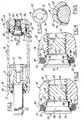
- FIG. 1 illustrated a gas spring 10 comprising a piston and rod assembly 12 reciprocable in a gas chamber 14 of a casing 16, with a sealing assembly 18 at the front end of the casing through which a piston rod 20 sealably extends.
- the piston rod 20 is slidably received in a permanently lubricated bronze bearing 21 disposed in a steel retainer ring fixed by shoulders rolled into the casing.
- An improved filler block 22 of the present invention serves as an end cap closing the rear end of the casing.
- the casing is an elongated, open-ended tubular member with end portions 24 and 26 turned radially inwardly as shown. Except for filler block 22 embodying the improved charging valve construction of the invention, the remainder of gas spring 10 is of known construction and hence not described in detail.
- Filler block 22 includes a generally cylindrical end cap 30 axially affixed and securely retained at the rear end of casing 16 by a shoulder rolled into the casing and rolled over end portion 26.
- Cap 30 has an external groove carrying an O-ring 32 for preventing escape of pressurized gas from chamber 14 between the cap and the casing 16.
- Cap 30 has a large diameter through-passageway defined successively by an internally threaded bore 34 opening at the rear face of the cap 30, an intermediate, internally threaded counterbore 36, and a slightly larger diameter concentric counterbore 38 opening at the inner, forward end face 40 of cap 30.
- Counterbore 38 has a smooth wall cylindrical surface 42 that terminates at the inner end of counterbore 38 with a radial face 44 (FIGS. 3 and 4) that defines a shoulder junction with counterbore 36.
- screw plug 50 is a solid imperforate member manufactured as a body of revolution having a generally circular head 54 with a cylindrical outside diameter surface 56 greater in diameter by a predetermined amount than that of counterbore surface 42.
- Head 54 also has a frusto-conical O-ring sealing surface 58 formed with a forwardly divergent straight taper angle, preferably a 30° included angle relative to the center line axis C/L of plug 50.
- Surface 58 extends axially from max diameter surface 56 to a cylindrical shoulder surface 60 concentric with surfaces 56 and 58 and having a diameter slightly smaller by a predetermined amount than the diameter of surface 42.
- Cylindrical portion 60 has a right angle shoulder 62 defined by its junction with a shank portion 64 of plug 50 which in turn terminates at a radial rear end face 66.
- Shank 64 is provided with external machine screw straight threads 68 running from end face 66 toward shoulder portion 60 and terminating at a conical transition portion 70 which flares outwardly to meet shoulder 62 where its maximum diameter is slightly less than that of counterbore 36.
- Plug threads 68 are designed to threadably interengage internal machine screw straight threads 72 provided in counterbore 36 of cap 30 with a predetermined radial clearance between the peaks of external threads 68 and the roots of internal threads 72, and vice versa, preferably on the order of .003 inches (.05 mm).
- Head 54 of screw plug 50 is also provided with a hexagonal blind socket 74 in its radial end face 76, as shown in FIG. 2.
- O-ring 52 in its free state condition has an inside diameter slightly less than the diameter of cylindrical surface 60 so as to be snugly received in pre-assembly on this surface prior to installation of plug 50 into cap 30.
- plug 50 with O-ring 52 so carried thereon is inserted shank end first into end counterbore 38 to start threads 68 into threads 72.
- Screw plug 50 is then rotated with a hex head driver tool (not shown) to thread plug 50 into its fully seated condition in cap 30, as shown in FIGS. 1 and 4 wherein shoulder 62 abuts shoulder 44.
- Plug 50 is preferably tightened down with a predetermined installation torque of 1-2 Lb.-In. max so that the trailing faces of external plug threads 68 bear lightly against the leading faces of the internal cap threads 72.
- the installed radial clearance between the peaks and roots threads 68 and 72 can be seen in FIG. 5 as well as in FIGS. 3 and 4.
- shoulder 62 and shoulder 44 Another, always-open gas leakage passageway is also provided between shoulder 62 and shoulder 44 when screw plug 50 has been so installed.
- shoulder 44 is notched, as by the end termination of thread 72 at shoulder 44 or by an additional notching operation.
- screw plug 50 may be backed off one-quarter to one-half turn after the aforementioned shoulder-to-shoulder initial seating to thereby slightly separate shoulder 62 from shoulder 44. Plug 50 is then held in this slightly backed-off position by the elastomeric spring biasing force developed in O-ring 52 during plug thread-in, as explained hereinafter
- O-ring 52 will abut end face 40 of cap 30 to yieldably force the O-ring up the slope of conical surface 58, thereby circumferentially stretching O-ring 52 to develop an elastic force between an annular sealing zone 78 of O-ring 52 that tangentially contacts and squeezes against the surface 58, and between another annular gas sealing zone 80 of O-ring 52 that tangentially contacts and squeezes against cap end face 40, as shown in the fully installed sealed condition of FIG. 4.
- O-ring 52 The extent of this "pre-compression" of O-ring 52 is thus controlled by cooperative dimensional geometry of O-ring with plug surfaces 62, 60 and 58 in further cooperation with the axial depth of shoulder surface 44 from end face 40 of cap 30.
- the filler block subassembly 22 is then installed into the rear end of casing 16 and affixed therein as shown in FIG. 1 by suitable roll curling and swaging operations.
- chamber 14 is first charged to a predetermined pressure with a suitable gas such as nitrogen.
- a suitable gas such as nitrogen.
- the hose has a threaded end fitting (not shown) adapted to be threadably received into the internal threads 84 of cap bore 34, until the hose coupling O-ring (not shown) is suitable sealably engaged with the outer end face 86 of cap 30.
- the tank valve is then opened to admit gas into bore 34 under sufficient regulated pressure, typically ranging between 200 to 2,000 psi, depending upon the desired charge pressure intended for chamber 14 with the piston rod assembly 12 fully extended, i.e., at the maximum volume condition of chamber 14.
- regulated pressure typically ranging between 200 to 2,000 psi, depending upon the desired charge pressure intended for chamber 14 with the piston rod assembly 12 fully extended, i.e., at the maximum volume condition of chamber 14.
- Such charging pressures are sufficient to force the charging gas through the leakage clearance between the plug threads 68 and cap threads 72 so that the gas first flows along and around shank 64, as shown diagrammatically by the small arrows in FIG. 3, and thence between the engaged but unsealed shoulder surfaces 44 and 62, thence through the annular clearance space 88 between surface 60 and surface 42, and then enters the "valve chamber" space 90 initially held sealed by the aforementioned pre-compression of O-ring 52 (FIG. 4).
- O-ring 52 and screw plug head surfaces 58 and 60 and cap seat 44 are sized relative to one another so that, as shown in FIG. 4, when chamber 14 is so pressurized O-ring 52 does not bottom out on the cylindrical surface 60 of plug 50.
- the O.D. of head surface 56 is also made large enough to retain the gas pressure-opened O-ring 52 in the sealing groove defined between bead surface 58 and cap surface 40 during rapid filling of chamber 14 with pressurized gas.
- Gas spring 16 can then be utilized as a pre-charged and self-contained unit. This unit can be one-way re-charged as needed, and the pre-charge pressure can be set as desired within the constraints of the strength of materials and construction of the gas spring relative to the maximum working pressure to be encountered in use when the piston rod is fully displaced into the cylinder.
- FIG. 6 illustrates a second embodiment filler block 22' of the invention installed and sealed in fixed relation in the rear end of casing 16.
- Filler block 22' is modified to provide for partial bleed-off adjustment of the gas pressure in chamber 14 or for emptying and recharging the gas spring to a predetermined desired pressure.
- Filler block 22' utilizes a slightly modified end cap 30' in which the central through passageway is axially lengthened by providing a cylindrical extension boss 100 protruding from the front end face 40 of the cap.
- Extension 100 is provided at its forward end with an annular radial surface 102 which functions in the manner of sealing face 40 of filler block 22.
- Extension 10 is also provided with the aforementioned counterbore 42 and shoulder 44 for threaded-stop seating of a modified screw-in plug 50'.
- Plug 50' may be made identical to plug 50 except that it is also provided with a central bleed passageway 104 extending axially between the rear end face 66 of plug 50' and the bottom face of the plug hex socket 74, and preferably of 0.030-0.050 of an inch in diameter.
- the central through-passageway of cap 30' is of constant rather than stepped diameter so that internal threads 72 are continuous for substantially the entire axial length of this passageway between shoulder 44 and cap end face 86. Again these threads are machine screw straight threads of constant pitch and constant peak and root dimensions.
- a flat-end bleed plug 108 is provided having external threads 110 engaging in passageway internal threads 72 in the same manner as the external threads 68 of screw plug 50'.
- Bleed plug 108 is provided with a hexagonal socket 110 for receiving a hexagonal male driving tool for rotatably threading the plug in cap bore 34'.
- a suitable flat gasket seal 112 in the form of a flat disc having an O.D. slightly less than the I.D. of thread 72 is captured between the flat forward face 114 of plug 108 and the rear face 66 of plug 50' and compressed therebetween to seal the rear end of bleed passageway 104'.
- plug 108 is threaded into place to force gasket seal 112 into sealing relationship with bleed passageway 104 so that pressurized gas cannot escape from chamber 14 via this bleed passageway.
- chamber 14 still can be charged by again coupling the hose fitting from the pressurized gas source threadably into the rear end of fill passageway 34' and admitting gas under pressure into the clearance space between the threads of plug 108 and the fitting and bore 34'.
- the pressurized gas will now first flow between the engaged external threads of bleed plug 108 and internal threads 72 of cap 30', and thence between external threads 68 of screw plug 50' and the engaged internal threads 72 of the cap fill passageway, and again will travel axially past the shoulder seat 44 even when engaged by plug 50' to thereby force O-ring 52 to its open condition as with the first embodiment as illustrated in FIG. 3.
- the second embodiment filler block '22 enables such adjustment by inserting a hex shank tool (not shown) into socket 110 of bleed plug 108 to rotate the plug in a loosening direction relative to gasket seal 112.
- pressurized gas in chamber 14 can bleed thereform via bleed passageway 104 and then radially outwardly over the adjacent face of gasket seal 112, and then into clearance space between the threads of bleed plug 108 and passageway 34', and thence out the open passageway 34' to ambient.
- the gas spring is allowed to so bleed until the pressure in chamber 14 is substantially at ambient pressure. Then plug 108 is retightened to seal the bleed passageway 104, and the recharging operation proceeds as described previously.
- O-ring 52 will remain compressed by the pressurized gas in chamber 14 through a small range of axial travel of screw plug 50' relative to end cap 30'. Hence, it cannot become unsealed and bleed off gas from chamber 14 even if bleed plug 108 is over tightened such that screw plug 50' is advanced slightly axially to the left to thereby slightly disengage shoulder 62 from shoulder 44.
- screw plugs 50 and 50' are manufactured as a separate part from end caps 30 and 30' in the form of body of revolution as a threaded screw plug, they may be readily economically manufactured as a screw machine part or as a cold headed and threaded part. There is no need to drill the small diameter lateral port 122 of the aforementioned '906 end cap embodiment of FIGS. 6-8 as disclosed therein, thereby obviating the manufacturing problems associated with making this passageway as well as the operational problems of the O-ring in sealing this lateral passageway.
- This feature also enables the use of a lower durometer O-ring material (e.g., a durometer of 70), which in turn improves sealing engagement between this softer more pliable O-ring and its associated seating surfaces over the full range of gas pressures, particularly at the lower end of the pressure range from 400 psi down to 200 psi.
- a lower durometer O-ring material e.g., a durometer of 70
- the capability of operation with a lower durometer O-ring material also enables the O-ring to better fill in imperfections, such as machining grooves, in the seating surfaces to thereby enhance reliability of the sealing action provided by the O-ring. Also, since there is no radial or lateral port drilled through the plug there are no burrs to remove.
- Both the plug sealing surface 58 as well as the radial end face sealing surface 40 or 102' are easier to manufacture to the required tolerances because they are planar surfaces individually formed in the manufacture of the separate pieces. Because there is a separate manufacture of the screw plugs 50 and 50', it is also easier to machine the desired surface finish on the plug sealing surfaces 58, and likewise on the radial end face sealing surface 40, 102 of the cap of the filler block, thereby further contributing to retention of O-ring 52 on the separate threaded screw plug part. Additionally, the dimensionally controlled threaded engagement and shoulder stop seating with the end cap renders it easier to control the extent of precompression of O-ring 52, i.e., the axial dimension from shoulder seat 44 to the installed location of plug sealing surface 58.
- the end cap charging valve construction of the filler blocks of the invention can be made for either no-chamber-bleed-off operation or chamber-bleed-off gas pressure adjustment of the gas springs.
- the one way filler check valve provided by the O-ring and screw plug is tamper proof once installed in the gas spring assembly.
Landscapes
- Engineering & Computer Science (AREA)
- General Engineering & Computer Science (AREA)
- Mechanical Engineering (AREA)
- Filling Or Discharging Of Gas Storage Vessels (AREA)
- Fluid-Damping Devices (AREA)
Applications Claiming Priority (2)
| Application Number | Priority Date | Filing Date | Title |
|---|---|---|---|
| US08/910,790 US5975507A (en) | 1997-08-13 | 1997-08-13 | Gas spring with filler block |
| US910790 | 1997-08-13 |
Publications (2)
| Publication Number | Publication Date |
|---|---|
| EP0897073A2 true EP0897073A2 (de) | 1999-02-17 |
| EP0897073A3 EP0897073A3 (de) | 2001-01-03 |
Family
ID=25429331
Family Applications (1)
| Application Number | Title | Priority Date | Filing Date |
|---|---|---|---|
| EP98115027A Withdrawn EP0897073A3 (de) | 1997-08-13 | 1998-08-10 | Gasfeder mit Füllkörperblock |
Country Status (2)
| Country | Link |
|---|---|
| US (1) | US5975507A (de) |
| EP (1) | EP0897073A3 (de) |
Cited By (5)
| Publication number | Priority date | Publication date | Assignee | Title |
|---|---|---|---|---|
| KR20020067375A (ko) * | 2001-02-16 | 2002-08-22 | 이상원 | 가스스프링 |
| EP1738098A4 (de) * | 2004-04-19 | 2009-12-09 | Conrader R Co | Elastomeres rückschlagventil |
| ITUA20164635A1 (it) * | 2016-06-24 | 2017-12-24 | Special Springs Srl | Molla a gas con dispositivo di sicurezza |
| CN110131495A (zh) * | 2019-05-22 | 2019-08-16 | 成都飞机工业(集团)有限责任公司 | 一种充气转接装置 |
| CN112957640A (zh) * | 2021-02-07 | 2021-06-15 | 宁波正欣消防设备有限公司 | 一种快速补充灭火剂的灭火器 |
Families Citing this family (8)
| Publication number | Priority date | Publication date | Assignee | Title |
|---|---|---|---|---|
| US6062352A (en) * | 1998-08-24 | 2000-05-16 | Piolax, Inc. | Air damper |
| US7458392B2 (en) * | 2005-09-13 | 2008-12-02 | R. Conrader Company | Spring actuated check valve |
| DE102009038225A1 (de) * | 2009-08-20 | 2011-02-24 | Schaeffler Technologies Gmbh & Co. Kg | Ringfederelement für einen hydraulischen Riemenspanner |
| US9400147B2 (en) * | 2010-05-06 | 2016-07-26 | Rock River Arms, Inc. | Firearm having gas piston system |
| AU2013273691B2 (en) * | 2012-12-21 | 2018-01-18 | Apex Valves Limited | Excess Pressure Safety Relief Valve |
| EP2829765B1 (de) * | 2013-07-23 | 2015-12-30 | Bordignon Silvano S.r.l. | Vorrichtung und Verfahren zur Überprüfung des Ladezustands einer Gasfeder |
| US10113605B2 (en) * | 2016-09-29 | 2018-10-30 | Dadco, Inc. | Overtravel relief assembly for a gas spring |
| ES2821198T3 (es) * | 2017-02-17 | 2021-04-23 | Special Springs Srl | Actuador de cilindro de gas con dispositivo de seguridad para retorno descontrolado del pistón-vastago |
Family Cites Families (10)
| Publication number | Priority date | Publication date | Assignee | Title |
|---|---|---|---|---|
| US3298394A (en) * | 1963-03-29 | 1967-01-17 | William J Chorkey | Check valve |
| US4838527A (en) * | 1987-03-03 | 1989-06-13 | Power Components, Inc. | Convertible gas spring |
| US4813655A (en) * | 1987-11-12 | 1989-03-21 | Rantom, Inc. | Control valve for gas spring |
| US4792128A (en) * | 1988-03-08 | 1988-12-20 | Power Components, Inc. | No grow gas spring |
| US5020570A (en) * | 1990-08-17 | 1991-06-04 | Power Components, Inc. | Combined valve modular control panel |
| CA2055917A1 (en) * | 1990-12-14 | 1992-06-15 | Bernard Joseph Wallis | Gas die cylinders |
| US5275387A (en) * | 1992-04-09 | 1994-01-04 | Power Components, Inc. | Gas spring |
| US5344125A (en) * | 1993-09-17 | 1994-09-06 | Diebolt International, Inc. | Gas spring with filler valve |
| DE4420474C2 (de) * | 1994-06-11 | 2001-11-29 | Guenther Hahn | Gaszugfeder |
| DE19520192C2 (de) * | 1995-06-01 | 2001-11-29 | Guenther Hahn | Einstellbare Gasfeder |
-
1997
- 1997-08-13 US US08/910,790 patent/US5975507A/en not_active Expired - Lifetime
-
1998
- 1998-08-10 EP EP98115027A patent/EP0897073A3/de not_active Withdrawn
Cited By (9)
| Publication number | Priority date | Publication date | Assignee | Title |
|---|---|---|---|---|
| KR20020067375A (ko) * | 2001-02-16 | 2002-08-22 | 이상원 | 가스스프링 |
| EP1738098A4 (de) * | 2004-04-19 | 2009-12-09 | Conrader R Co | Elastomeres rückschlagventil |
| ITUA20164635A1 (it) * | 2016-06-24 | 2017-12-24 | Special Springs Srl | Molla a gas con dispositivo di sicurezza |
| EP3260726A1 (de) * | 2016-06-24 | 2017-12-27 | Special Springs S.r.l. | Gaszylinderaktuator mit sicherheitsvorrichtung |
| US10619695B2 (en) | 2016-06-24 | 2020-04-14 | Special Springs S.R.L. | Gas cylinder actuator with safety device |
| CN110131495A (zh) * | 2019-05-22 | 2019-08-16 | 成都飞机工业(集团)有限责任公司 | 一种充气转接装置 |
| CN110131495B (zh) * | 2019-05-22 | 2024-06-07 | 成都飞机工业(集团)有限责任公司 | 一种充气转接装置 |
| CN112957640A (zh) * | 2021-02-07 | 2021-06-15 | 宁波正欣消防设备有限公司 | 一种快速补充灭火剂的灭火器 |
| CN112957640B (zh) * | 2021-02-07 | 2022-04-26 | 宁波正欣消防设备有限公司 | 一种快速补充灭火剂的灭火器 |
Also Published As
| Publication number | Publication date |
|---|---|
| US5975507A (en) | 1999-11-02 |
| EP0897073A3 (de) | 2001-01-03 |
Similar Documents
| Publication | Publication Date | Title |
|---|---|---|
| US5975507A (en) | Gas spring with filler block | |
| US5275387A (en) | Gas spring | |
| US5344125A (en) | Gas spring with filler valve | |
| EP0427468B1 (de) | Gasfeder | |
| AU630996B2 (en) | Pressure limiting valve with teflon seal | |
| US4354523A (en) | Lubricant fitting for a valve | |
| US20140191452A1 (en) | Gas Spring and Overpressure Relief and Fill Valve Assembly | |
| US5088698A (en) | Sealing construction for a gas spring | |
| EP2754915A2 (de) | Gasfeder und Überdruckentlüftungsstecker | |
| CA2083552C (en) | Gas spring | |
| EP2037148A2 (de) | Gasfeder mit Führung | |
| CN104755788A (zh) | 弹簧制动气室 | |
| EP0997662B1 (de) | Gasfederfüllventil | |
| US6286641B1 (en) | Oil brake | |
| US5437436A (en) | Stand-alone gas spring | |
| US4821775A (en) | One shot valve | |
| US4475339A (en) | Apparatus for controlling braking liquid pressure | |
| US20060032369A1 (en) | Piston-piston rod retaining assembly for a hydraulic piston and cylinder unit | |
| GB2298812A (en) | Rivet setting tool | |
| JP3054996B2 (ja) | 安全弁 | |
| US5127437A (en) | Valve | |
| US6981612B2 (en) | Tamper-proof gas pin valve | |
| US6213566B1 (en) | Brake proportioning in-line ball valve | |
| US6935110B2 (en) | Tandem master cylinders for hydraulic systems | |
| US4487110A (en) | Clamping element |
Legal Events
| Date | Code | Title | Description |
|---|---|---|---|
| PUAI | Public reference made under article 153(3) epc to a published international application that has entered the european phase |
Free format text: ORIGINAL CODE: 0009012 |
|
| AK | Designated contracting states |
Kind code of ref document: A2 Designated state(s): AT BE CH DE DK ES FR GB IT LI SE |
|
| AX | Request for extension of the european patent |
Free format text: AL;LT;LV;MK;RO;SI |
|
| RIN1 | Information on inventor provided before grant (corrected) |
Inventor name: COTTER, PATRICK J. |
|
| PUAL | Search report despatched |
Free format text: ORIGINAL CODE: 0009013 |
|
| RIC1 | Information provided on ipc code assigned before grant |
Free format text: 7F 16F 9/43 A, 7F 16K 15/14 B |
|
| AK | Designated contracting states |
Kind code of ref document: A3 Designated state(s): AT BE CH CY DE DK ES FI FR GB GR IE IT LI LU MC NL PT SE |
|
| AX | Request for extension of the european patent |
Free format text: AL;LT;LV;MK;RO;SI |
|
| 17P | Request for examination filed |
Effective date: 20010418 |
|
| AKX | Designation fees paid |
Free format text: AT BE CH DE DK ES FR GB IT LI SE |
|
| GRAH | Despatch of communication of intention to grant a patent |
Free format text: ORIGINAL CODE: EPIDOS IGRA |
|
| STAA | Information on the status of an ep patent application or granted ep patent |
Free format text: STATUS: THE APPLICATION IS DEEMED TO BE WITHDRAWN |
|
| 18D | Application deemed to be withdrawn |
Effective date: 20031016 |