EP0896124B1 - System of multiple-purpose tools for the connection of pipes - Google Patents
System of multiple-purpose tools for the connection of pipes Download PDFInfo
- Publication number
- EP0896124B1 EP0896124B1 EP98401836A EP98401836A EP0896124B1 EP 0896124 B1 EP0896124 B1 EP 0896124B1 EP 98401836 A EP98401836 A EP 98401836A EP 98401836 A EP98401836 A EP 98401836A EP 0896124 B1 EP0896124 B1 EP 0896124B1
- Authority
- EP
- European Patent Office
- Prior art keywords
- cleaning
- pipes
- devices
- arms
- support
- Prior art date
- Legal status (The legal status is an assumption and is not a legal conclusion. Google has not performed a legal analysis and makes no representation as to the accuracy of the status listed.)
- Expired - Lifetime
Links
Images


Classifications
-
- B—PERFORMING OPERATIONS; TRANSPORTING
- B08—CLEANING
- B08B—CLEANING IN GENERAL; PREVENTION OF FOULING IN GENERAL
- B08B9/00—Cleaning hollow articles by methods or apparatus specially adapted thereto
- B08B9/02—Cleaning pipes or tubes or systems of pipes or tubes
- B08B9/021—Cleaning pipe ends or pipe fittings, e.g. before soldering
-
- E—FIXED CONSTRUCTIONS
- E21—EARTH DRILLING; MINING
- E21B—EARTH DRILLING, e.g. DEEP DRILLING; OBTAINING OIL, GAS, WATER, SOLUBLE OR MELTABLE MATERIALS OR A SLURRY OF MINERALS FROM WELLS
- E21B41/00—Equipment or details not covered by groups E21B15/00 - E21B40/00
- E21B41/04—Manipulators for underwater operations, e.g. temporarily connected to well heads
-
- E—FIXED CONSTRUCTIONS
- E21—EARTH DRILLING; MINING
- E21B—EARTH DRILLING, e.g. DEEP DRILLING; OBTAINING OIL, GAS, WATER, SOLUBLE OR MELTABLE MATERIALS OR A SLURRY OF MINERALS FROM WELLS
- E21B43/00—Methods or apparatus for obtaining oil, gas, water, soluble or meltable materials or a slurry of minerals from wells
- E21B43/01—Methods or apparatus for obtaining oil, gas, water, soluble or meltable materials or a slurry of minerals from wells specially adapted for obtaining from underwater installations
- E21B43/013—Connecting a production flow line to an underwater well head
-
- Y—GENERAL TAGGING OF NEW TECHNOLOGICAL DEVELOPMENTS; GENERAL TAGGING OF CROSS-SECTIONAL TECHNOLOGIES SPANNING OVER SEVERAL SECTIONS OF THE IPC; TECHNICAL SUBJECTS COVERED BY FORMER USPC CROSS-REFERENCE ART COLLECTIONS [XRACs] AND DIGESTS
- Y10—TECHNICAL SUBJECTS COVERED BY FORMER USPC
- Y10T—TECHNICAL SUBJECTS COVERED BY FORMER US CLASSIFICATION
- Y10T29/00—Metal working
- Y10T29/49—Method of mechanical manufacture
- Y10T29/49718—Repairing
- Y10T29/49719—Seal or element thereof
-
- Y—GENERAL TAGGING OF NEW TECHNOLOGICAL DEVELOPMENTS; GENERAL TAGGING OF CROSS-SECTIONAL TECHNOLOGIES SPANNING OVER SEVERAL SECTIONS OF THE IPC; TECHNICAL SUBJECTS COVERED BY FORMER USPC CROSS-REFERENCE ART COLLECTIONS [XRACs] AND DIGESTS
- Y10—TECHNICAL SUBJECTS COVERED BY FORMER USPC
- Y10T—TECHNICAL SUBJECTS COVERED BY FORMER US CLASSIFICATION
- Y10T29/00—Metal working
- Y10T29/49—Method of mechanical manufacture
- Y10T29/49718—Repairing
- Y10T29/49721—Repairing with disassembling
- Y10T29/49723—Repairing with disassembling including reconditioning of part
- Y10T29/49725—Repairing with disassembling including reconditioning of part by shaping
- Y10T29/49726—Removing material
-
- Y—GENERAL TAGGING OF NEW TECHNOLOGICAL DEVELOPMENTS; GENERAL TAGGING OF CROSS-SECTIONAL TECHNOLOGIES SPANNING OVER SEVERAL SECTIONS OF THE IPC; TECHNICAL SUBJECTS COVERED BY FORMER USPC CROSS-REFERENCE ART COLLECTIONS [XRACs] AND DIGESTS
- Y10—TECHNICAL SUBJECTS COVERED BY FORMER USPC
- Y10T—TECHNICAL SUBJECTS COVERED BY FORMER US CLASSIFICATION
- Y10T29/00—Metal working
- Y10T29/49—Method of mechanical manufacture
- Y10T29/49764—Method of mechanical manufacture with testing or indicating
- Y10T29/49769—Using optical instrument [excludes mere human eyeballing]
-
- Y—GENERAL TAGGING OF NEW TECHNOLOGICAL DEVELOPMENTS; GENERAL TAGGING OF CROSS-SECTIONAL TECHNOLOGIES SPANNING OVER SEVERAL SECTIONS OF THE IPC; TECHNICAL SUBJECTS COVERED BY FORMER USPC CROSS-REFERENCE ART COLLECTIONS [XRACs] AND DIGESTS
- Y10—TECHNICAL SUBJECTS COVERED BY FORMER USPC
- Y10T—TECHNICAL SUBJECTS COVERED BY FORMER US CLASSIFICATION
- Y10T29/00—Metal working
- Y10T29/53—Means to assemble or disassemble
- Y10T29/53087—Means to assemble or disassemble with signal, scale, illuminator, or optical viewer
Definitions
- the present invention relates to a multi-tool system usable for the connection of flexible or rigid pipes and, more especially for inspection, cleaning and replacement organs in underwater oil installations.
- connection systems are designed so that the connection means are mounted in an end device which is integral with the fixed assembly.
- the verification tests sealing performed before operational use of the pipeline or periodically in use are defective, it is necessary repair or change the connection means and, in particular, the sealing members. Therefore, one or more complicated interventions and very expensive are essential because the organs requiring or the interventions are arranged inside the fixed assembly.
- the subject of this last request concerns in particular a receptacle which is integral with the fixed structure on which is mounted a flexible pipe considered to be fixed, said receptacle receiving, at inside, the two ends of the fixed and mobile flexible pipes to connect.
- the receptacle includes a front wall and a rear wall for passage of pipe ends, dimensions internal of said receptacle being chosen such that the interior space is sufficient to completely move the locking means of the ends connected in their final connection position.
- the object of the present invention is to propose a multi-tool system or intervention unit, which can be ordered by the ROV when it is independent of the latter, that is to say not included in the ROV, or which can be integrated into the ROV, for example housed in the lower case if possible.
- the present invention relates to a multi-tool system for the inspection, cleaning and replacement of organs in a petroleum installation, characterized in that it comprises a support on which are mounted means capable of moving laterally to at least two devices in opposite directions, at least one of said devices being capable of being rotated around a of said directions.
- An advantage of the present invention is that it is possible to inspect the elements or organs arranged in the receptacle when the fixed installation has one, before any intervention.
- the same system can be used in underwater installations and whether or not including a receptacle.
- Another advantage of the present invention is that after the inspection, the system can carry out, if necessary, a cleaning said elements and / or members housed in the receptacle.
- the multi-tool system is intended to be implemented in a fixed underwater installation, said installation being shown partially and comprising a fixed structure 1 on which is mounted a receptacle 2 for receiving the fixed end 3 of a flexible pipe and the movable end 4 of another flexible pipe, said fixed 3 and mobile 4 ends having the same axis 36 and are shown in their non-connected state, the locking means 5 having been unlocked, via a locking device locking / unlocking 6, in order to allow the separation of said ends 3 and 4.
- the multi-tool system 7 comprises a support frame or cassette 8 on which are mounted two arms 9 and 10 which pivot at one of their ends around pivot axes 11 mounted on a workpiece support 12 of the cassette 8.
- the end 13 of the arm 10 is inclined towards the interior and it is provided with an oblong hole 14.
- the end 15 of the arm 9 is also inclined towards the inside of the cassette and comprises also an oblong hole 16, the end 15 having a longer length as large as that of end 13.
- Arms 9 and 10 are moved laterally in opposite directions which are, in the examples shown, aligned with the axis 36 of the ends 3 and 4 of the pipes, at by means of a double jack 17 comprising two rods 18 and 19 connected arms 9 and 10 respectively. It is also possible to use two separate cylinders each acting on one of the arms 18, 19.
- the support assembly 20 includes a device for changing and fitting 22 of a seal 23 mounted in the fixed end 3, a stud 24 being inserted into the oblong hole 16 and fixed at one end of an end piece 25.
- the change and setting elements place 22 includes three regularly distributed units, for example at 120 ° from each other, on a plate 26 ( Figure 5). All support 21 comprises an end plate 27 provided with a stud 28 which is inserted into the oblong hole 14.
- a device 29 comprises a plate 30 driven in rotation by a motor 31 and on which a camera 32 is mounted, at least one cleaning brush 33 and at least one nozzle 34 for propelling a jet of cleaning fluid (Figure 4).
- the motor 31 rotates the device 29 relative to the support assembly 21, the axis of rotation of the motor 31 being aligned for example with axis 36.
- a handle 35 is fixed on the cassette 8 and allows the manipulation of the multi-tool system using an ROV, cassette 8 being likely to rotate around the axis 36.
- the multi-tool system is brought by the ROV into receptacle 2, with the two arms 9 and 10 in their close position, as shown in Figure 1.
- a first phase (FIG. 2), the jack 17 is actuated to extend the rod 18 which pushes the arm 9 while doing so pivot around its pivot axis 11 until the stud 24 comes into abutment at the bottom of the oblong hole 16. Then, under the action of the jack 17, the entire support 20 is translated on its guide rails up to that the device 22 comes into the appropriate position for removing the seal 23, gripping and 37 or placement members a new seal being provided for this purpose on the device 22. When the gasket has been removed, the assembly 20 is returned to its initial position and the assembly 21 is moved towards the movable end 4 under the action of the jack 17 and the rod 19 which pivots the arm 10 until the device 29 either in the inspection and cleaning position.
- the camera 32 inspects the surface condition of the contact surfaces 38 of the movable end 4.
- the device 29 is rotated so that the nozzles 34 project a jet of cleaning liquid, after which the brushes 33 are actuated to clean the entire surface of said surfaces 38.
- Cassette 8 is extracted from receptacle 2 to evacuate the seal defective and recovery of a new seal.
- Cassette 8 fitted with a new seal is introduced again, in its initial position, in the receptacle 2 for the installation of said new seal on the bearing surfaces 39.
- Figures 6 to 8 show a second embodiment of the multi-tool system according to the invention.
- the cassette 8 is equipped with a frame on which are mounted a pair of devices 29 and 29a and a pair of devices 22 and 22a, the frame being capable of rotate, inside the cassette 8, around a vertical axis 40, so successively bring the devices concerned into their position work i.e. with regard to the elements to be inspected, cleaned or switch.
- Each device 29, 29a comprises a camera 32, nozzles for liquid propulsion 34 and at least one brush 33 and one motor 31.
- each device 22, 22a comprises means for receipt of a new seal 23a and means for removing seal 23 from the fixed end 3.
- a new seal 23a is mounted on a device 22a while the other device 22 proceeds to removal of the gasket to be replaced 23.
- the inspection and cleaning devices 29 ranges 38 and 39 of the movable and fixed ends are in action, the brushes 33 cleaning said staves.
Abstract
Description
La présente invention concerne un système multi-outils utilisable pour le raccordement de conduites flexibles ou rigides et, plus particulièrement pour l'inspection, le nettoyage et le remplacement d'organes dans des installations pétrolières sous-marines.The present invention relates to a multi-tool system usable for the connection of flexible or rigid pipes and, more especially for inspection, cleaning and replacement organs in underwater oil installations.
Dans l'industrie pétrolière et plus particulièrement dans l'exploitation pétrolière en mer, loin des côtes, les installations sous-marines sont parfois à de grandes profondeurs atteignant 1 000 m et même davantage. Pour réaliser des connexions entre divers ensembles des installations sous-marines, sans faire appel à des plongeurs ou à des techniques similaires, on utilise, de plus en plus, certains types de robots télécommandés depuis la surface (ROV en anglais, acronyme de Remotely Operated Vehicle) qui sont capables de transporter et/ou de déplacer des charges plus ou moins lourdes et d'effectuer des opérations diverses et variées telles que des connexions entre des éléments et des installations sous-marines.In the petroleum industry and more particularly in offshore oil exploitation, far from the coast, underwater installations are sometimes at great depths reaching 1000 m and even more. To make connections between various sets of underwater installations, without the need for divers or similar techniques, we are using more and more certain types of robots remotely controlled from the surface (ROV in English, acronym of Remotely Operated Vehicle) which are capable of transporting and / or moving more or less heavy loads and to perform various operations and varied such as connections between elements and installations submarines.
Les systèmes de connexion connus sont réalisés de sorte que les moyens de raccordement sont montés dans un dispositif d'extrémité qui est solidaire de l'ensemble fixe. Lorsque les essais de vérification d'étanchéité effectués avant l'utilisation opérationnelle de la canalisation ou périodiquement en cours d'utilisation, sont défectueux, il est nécessaire de réparer ou changer les moyens de raccordement et, en particulier, les organes d'étanchéité. Dès lors, une ou plusieurs interventions compliquées et très onéreuses sont indispensables du fait que les organes nécessitant la ou les interventions sont disposés à l'intérieur de l'ensemble fixe.Known connection systems are designed so that the connection means are mounted in an end device which is integral with the fixed assembly. When the verification tests sealing performed before operational use of the pipeline or periodically in use, are defective, it is necessary repair or change the connection means and, in particular, the sealing members. Therefore, one or more complicated interventions and very expensive are essential because the organs requiring or the interventions are arranged inside the fixed assembly.
Pour remédier à ces inconvénients, la demanderesse a proposé, dans une demande déposée le 14 juin 1996 sous le n° 96 07 429 (FR-A-2 749 918), d'intégrer les moyens d'étanchéité et de verrouillage dans une cassette flottante qui constitue une interface entre les extrémités des conduites à raccorder, ladite cassette participant également au guidage et au centrage desdites extrémités à raccorder. To remedy these drawbacks, the applicant has proposed, in an application filed on June 14, 1996 under No. 96 07 429 (FR-A-2 749 918), integrate the sealing and locking means in a cassette floating which constitutes an interface between the ends of the pipes to connect, said cassette also participating in guiding and centering of said ends to be connected.
Toutefois, les utilisateurs préfèrent parfois monter les moyens de verrouillage soit sur l'extrémité fixe avant le raccordement soit sur les deux extrémités après raccordement.However, users sometimes prefer to mount the means either on the fixed end before connection or on the two ends after connection.
Une solution qui prend en compte cette considération de montage direct des moyens d'étanchéité tout en assurant un raccordement correct des extrémités des conduites à raccorder est décrite dans une autre demande de la déposante et portant le n° 97 06 314 (FR-A-2 763 636).A solution that takes this consideration of direct mounting of the sealing means while ensuring a connection correct of the ends of the pipes to be connected is described in another request of the applicant and bearing the number 97 06 314 (FR-A-2 763 636).
L'objet de cette dernière demande concerne notamment un réceptacle qui est solidaire de la structure fixe sur laquelle est montée une conduite flexible considérée comme fixe, ledit réceptacle recevant, à l'intérieur, les deux extrémités des conduites flexibles fixe et mobile à raccorder. A cet effet, le réceptacle comprend une paroi frontale et une paroi arrière pour le passage des extrémités des conduites, les dimensions internes dudit réceptacle étant choisies de telle sorte que l'espace intérieur soit suffisant pour déplacer entièrement les moyens de verrouillage des extrémités raccordées dans leur position finale de raccordement.The subject of this last request concerns in particular a receptacle which is integral with the fixed structure on which is mounted a flexible pipe considered to be fixed, said receptacle receiving, at inside, the two ends of the fixed and mobile flexible pipes to connect. For this purpose, the receptacle includes a front wall and a rear wall for passage of pipe ends, dimensions internal of said receptacle being chosen such that the interior space is sufficient to completely move the locking means of the ends connected in their final connection position.
Toutefois, il existe un besoin concernant l'inspection et/ou le nettoyage des faces en contact des extrémités des conduites avant la mise en place et/ou le changement des moyens d'étanchéité et/ou de verrouillage.However, there is a need for inspection and / or cleaning the contacting faces of the ends of the pipes before placing in place and / or changing the sealing means and / or locking.
En effet, jusqu'à présent, lorsqu'on doit mettre en place ou changer les moyens de verrouillage pour une raison quelconque, par exemple, par suite d'une usure prématurée ou normale, lesdits moyens de verrouillage sont tout simplement amenés dans leur position appropriée sans avoir procédé à une inspection des extrémités à raccorder. De la même manière, les organes d'étanchéité qui sont utilisés sur au moins une desdites conduites sont, après usure ou périodiquement, remplacés par des organes d'étanchéité neufs sans examen préalable des zones de support correspondantes. Or, en raison des fluides plus ou moins corrosifs qui peuvent circuler dans les conduites flexibles, il peut arriver que certaines parties d'une ou des deux conduites flexibles, situées dans la zone de raccordement, soient sinon endommagées du moins encrassées. Quand une intervention de nettoyage, par exemple, doit être effectuée, il n'y a, à l'heure actuelle, aucune solution susceptible de répondre à ce besoin. Même le caisson qui est disposé généralement sur la base du ROV et qui, en principe, contient des éléments nécessaires à une intervention sur le site ne contient pas d'outils spécifiques sauf ceux pour la manutention de certains organes de l'installation sous-marine, comme exemple l'enlèvement, la pose des moyens de verrouillage ou encore l'enlèvement et la pose des organes d'étanchéité.Indeed, until now, when we have to set up or change the locking means for any reason, for example example, as a result of premature or normal wear, said means of lock are simply brought into their proper position without having carried out an inspection of the ends to be connected. Of the same way, the sealing members that are used on at least one said pipes are, after wear or periodically, replaced by new sealing elements without prior examination of the support zones corresponding. However, due to the more or less corrosive fluids which can circulate in flexible pipes, it can happen that some parts of one or both flexible pipes, located in the area of connection, are otherwise damaged at least fouled. When a cleaning intervention, for example, must be carried out, there is, at At present, no solution is likely to meet this need. Even the box which is generally placed on the basis of the ROV and which, in principle, contains elements necessary for intervention on the site does not contain specific tools except those for handling certain parts of the underwater installation, as an example removal, installation of locking means or removal and fitting the sealing members.
La présente invention a pour but de proposer un système multi-outils ou unité d'intervention, qui peut être commandé par le ROV lorsqu'il est indépendant de ce dernier, c'est-à-dire non compris dans le ROV, ou qui peut être intégré dans le ROV, par exemple logé dans le caisson inférieur si cela est possible.The object of the present invention is to propose a multi-tool system or intervention unit, which can be ordered by the ROV when it is independent of the latter, that is to say not included in the ROV, or which can be integrated into the ROV, for example housed in the lower case if possible.
La présente invention a pour objet un système multi-outils pour l'inspection, le nettoyage et le remplacement d'organes dans une installation pétrolière, caractérisé en ce qu'il comprend un support sur lequel sont montés des moyens susceptibles de déplacer latéralement au moins deux dispositifs dans des directions opposées, au moins un desdits dispositifs étant susceptible d'être entraíné en rotation autour d'une desdites directions.The present invention relates to a multi-tool system for the inspection, cleaning and replacement of organs in a petroleum installation, characterized in that it comprises a support on which are mounted means capable of moving laterally to at least two devices in opposite directions, at least one of said devices being capable of being rotated around a of said directions.
Un avantage de la présente invention réside dans le fait qu'il est possible de procéder à une inspection des éléments ou organes disposés dans le réceptacle lorsque l'installation fixe en comporte un, avant toute intervention. Bien entendu, le même système peut être utilisé dans des installations sous-marines et comportant ou non un réceptacle.An advantage of the present invention is that it is possible to inspect the elements or organs arranged in the receptacle when the fixed installation has one, before any intervention. Of course, the same system can be used in underwater installations and whether or not including a receptacle.
Un autre avantage de la présente invention est qu'après l'inspection, le système peut effectuer, si besoin était, un nettoyage desdits éléments et/ou organes logés dans le réceptacle.Another advantage of the present invention is that after the inspection, the system can carry out, if necessary, a cleaning said elements and / or members housed in the receptacle.
D'autres avantages et caractéristiques ressortiront mieux à la lecture de la description de deux modes de réalisation selon l'invention, ainsi que des dessins annexés sur lesquels :
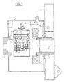
- la figure 1 est une vue schématique en élévation et partiellement en coupe d'un premier mode de réalisation du système selon la présente invention et disposé dans un réceptacle équipant une structure fixe,
- la figure 2 est la même vue que la figure 1, le système étant dans une position de travail,
- la figure 3 est la même vue que la figure 1, le système étant dans une autre position de travail,
- les figures 4 et 5 sont d'autres vues latérales du système multi-outils des figures 1 à 3,
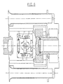
- la figure 6 est une vue de dessus du système selon un deuxième mode de réalisation de l'invention,
- les figures 7 et 8 sont des vues de côté du système représenté sur la figure 6.
- FIG. 1 is a schematic view in elevation and partially in section of a first embodiment of the system according to the present invention and disposed in a receptacle fitted to a fixed structure,
- FIG. 2 is the same view as FIG. 1, the system being in a working position,
- FIG. 3 is the same view as FIG. 1, the system being in another working position,
- FIGS. 4 and 5 are other side views of the multi-tool system of FIGS. 1 to 3,
- FIG. 6 is a top view of the system according to a second embodiment of the invention,
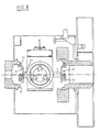
- Figures 7 and 8 are side views of the system shown in Figure 6.
Selon un premier mode de réalisation représenté sur les figures
1 à 5, le système multi-outils est destiné à être mis en oeuvre dans une
installation fixe sous-marine, ladite installation étant représenté
partiellement et comprenant une structure fixe 1 sur laquelle est monté un
réceptacle 2 pour la réception de l'extrémité fixe 3 d'une conduite flexible
et de l'extrémité mobile 4 d'une autre conduite flexible, lesdites
extrémités fixe 3 et mobile 4 ayant un même axe 36 et sont représentées
dans leur état de non raccordement, les moyens de verrouillage 5 ayant été
déverrouillés, par l'intermédiaire d'un organe de
verrouillage/déverrouillage 6, afin de permettre la séparation desdites
extrémités 3 et 4.According to a first embodiment shown in the figures
1 to 5, the multi-tool system is intended to be implemented in a
fixed underwater installation, said installation being shown
partially and comprising a
Le système multi-outils 7 comprend un châssis support ou
cassette 8 sur lequel sont montés deux bras 9 et 10 qui pivotent à une de
leurs extrémités autour d'axes de pivotement 11 montés sur une pièce
support 12 de la cassette 8. L'extrémité 13 du bras 10 est inclinée vers
l'intérieur et elle est pourvue d'un trou oblong 14. L'extrémité 15 du bras
9 est également inclinée vers l'intérieur de la cassette et comprend
également un trou oblong 16, l'extrémité 15 présentant une longueur plus
grande que celle de l'extrémité 13. Les bras 9 et 10 sont déplacés
latéralement dans des directions opposées qui sont, dans les exemples
représentés, alignées avec l'axe 36 des extrémités 3 et 4 des conduites, au
moyen d'un vérin double 17 comprenant deux tiges 18 et 19 reliées
respectivement aux bras 9 et 10. Il est également possible d'utiliser deux
vérins distincts agissant chacun sur un des bras 18, 19.The
Deux ensembles de support 20 et 21 sont montés coulissants
dans des glissières appropriées qui sont fixées dans la cassette 8 (figure
2). L'ensemble de support 20 comprend un dispositif de changement et de
mise en place 22 d'un joint d'étanchéité 23 monté dans l'extrémité fixe 3,
un téton 24 étant inséré dans le trou oblong 16 et fixé à une extrémité
d'une pièce d'extrémité 25. Les éléments de changement et de mise en
place 22 comprennent trois unités régulièrement réparties, par exemple à
120° les unes des autres, sur une plaque 26 (figure 5). L'ensemble de
support 21 comprend une plaque d'extrémité 27 munie d'un téton 28 qui
est inséré dans le trou oblong 14.Two
Un dispositif 29 comprend un plateau 30 entraíné en rotation
par un moteur 31 et sur lequel sont montées une caméra 32, au moins une
brosse de nettoyage 33 et au moins une buse 34 de propulsion d'un jet de
liquide de nettoyage (figure 4). Le moteur 31 entraíne en rotation le
dispositif 29 par rapport à l'ensemble support 21, l'axe de rotation du
moteur 31 étant aligné par exemple avec l'axe 36.A
Une poignée 35 est fixée sur la cassette 8 et permet la
manipulation du système multi-outils à l'aide d'un ROV, la cassette 8
étant susceptible de tourner autour de l'axe 36.A
Le fonctionnement de ce premier mode de réalisation du système multi-outils selon l'invention est le suivant.The operation of this first embodiment of the Multi-tool system according to the invention is as follows.
Après avoir écarté les deux extrémités 3 et 4 l'une de l'autre, le
système multi-outils est amené par le ROV dans le réceptacle 2, avec les
deux bras 9 et 10 dans leur position rapprochée, ainsi que représenté sur
la figure 1.After having separated the two
Dans une première phase (figure 2), le vérin 17 est actionné
pour mettre en extension la tige 18 qui pousse le bras 9 en le faisant
pivoter autour de son axe de pivotement 11 jusqu'à ce que le téton 24
vienne en butée au fond du trou oblong 16. Puis, sous l'action du vérin
17, l'ensemble du support 20 est translaté sur ses rails de guidage jusqu'à
ce que le dispositif 22 vienne dans la position adéquate d'enlèvement du
joint d'étanchéité 23, des organes de préhension 37 et/ou de mise en place
d'un nouveau joint étant prévus à cet effet sur le dispositif 22. Lorsque le
joint a été enlevé, l'ensemble 20 est ramené à sa position initiale et
l'ensemble 21 est déplacé vers l'extrémité mobile 4 sous l'action du vérin
17 et de la tige 19 qui fait pivoter le bras 10 jusqu'à ce que le dispositif 29
soit dans la position d'inspection et de nettoyage. Dans une première
étape, la caméra 32 inspecte l'état de surface des portées de contact 38 de
l'extrémité mobile 4. Lorsque ces portées nécessitent un nettoyage, le
dispositif 29 est mis en rotation pour que les buses 34 projettent un jet de
liquide de nettoyage, après quoi les brosses 33 sont actionnées pour
nettoyer la totalité de la surface desdites portées 38.In a first phase (FIG. 2), the jack 17 is actuated
to extend the
Après le nettoyage des portées 38, on peut procéder à
l'inspection et éventuellement au nettoyage des portées 39 de l'extrémité
fixe 3 une fois que le joint d'étanchéité 23 a été enlevé (figure 3). A cet
effet, la cassette 8 est extraite du réceptacle par le ROV qui la tourne de
180° pour amener le dispositif 29 en regard de l'extrémité fixe 3. Après
quoi, la caméra inspecte les portées 39 en vue d'un nettoyage éventuel.After cleaning the
La cassette 8 est extraite du réceptacle 2 pour évacuer le joint
défectueux et la récupération d'un joint neuf. La cassette 8 équipée d'un
joint neuf, est introduite à nouveau, dans sa position initiale, dans le
réceptacle 2 pour la mise en place dudit joint neuf sur les portées 39.Cassette 8 is extracted from
Une fois que le nettoyage est terminé et un nouveau joint 23 est
mis en place le système multi-outils est retiré par le ROV du réceptacle 2.
Après quoi, les moyens de verrouillage sont écartés pour permettre le
raccordement des extrémités 3 et 4 puis à nouveau actionnés pour
verrouiller lesdites extrémités 3 et 4 dans leur position finale de
raccordement.Once cleaning is complete and a
Les figures 6 à 8 représentent un deuxième mode de réalisation du système multi-outils selon l'invention.Figures 6 to 8 show a second embodiment of the multi-tool system according to the invention.
Dans le système représenté sur les figures 6 à 8, la cassette 8
est équipée d'un cadre sur lequel sont montées une paire de dispositifs 29
et 29a et une paire de dispositifs 22 et 22a, le cadre étant susceptible de
tourner, à l'intérieur de la cassette 8, autour d'un axe vertical 40, afin
d'amener successivement les dispositifs concernés dans leur position de
travail c'est-à-dire en regard des éléments à inspecter, nettoyer ou à
changer. Chaque dispositif 29, 29a comprend une caméra 32, des buses de
propulsion de liquide 34 et au moins une brosse 33 et un moteur 31. De la
même manière, chaque dispositif 22, 22a comprend des moyens de
réception d'un joint neuf 23a et de moyens d'enlèvement du joint 23 de
l'extrémité fixe 3. In the system shown in Figures 6 to 8, the cassette 8
is equipped with a frame on which are mounted a pair of
Comme cela apparaít sur les figures 6 et 7, un joint neuf 23a
est monté sur un dispositif 22a alors que l'autre dispositif 22 procède à
l'enlèvement du joint à remplacer 23.As shown in Figures 6 and 7, a new seal 23a
is mounted on a device 22a while the
Sur la figure 8, les dispositifs 29 d'inspection et de nettoyage
des portées 38 et 39 des extrémités mobile et fixe sont en action, les
brosses 33 nettoyant lesdites portées.In FIG. 8, the inspection and
Claims (10)
- A multi-tool system for inspecting, cleaning and replacing members in a sub-marine oil installation, which system comprises a support (8) on which there are mounted means (9, 10, 17) capable of laterally shifting at least two devices (22, 29) in opposite directions, it being possible for at least one of said devices (29) to be rotated about one of said directions.
- The system as claimed in claim 1, which comprises at least one inspection and cleaning device (29).
- The system as claimed in claim 1, wherein one of the devices (22) consists of means of removing and fitting a seal (23) mounted on one end (3) of a flexible pipe.
- The system as claimed in claims 1 to 3, wherein the shifting means consist of at least two arms (9, 10) each of which is moved toward one end (3, 4) of a flexible pipe, said ends (3, 4) of the flexible pipes being arranged facing one another and separated by a space, said ends having the same longitudinal axis (36).
- The system as claimed in one of claims 1 to 4, wherein the support consists of a housing (8) on which said arms are mounted so that they can pivot.
- The system as claimed in claim 4, which comprises displacement means (17) acting on said arms.
- The system as claimed in claim 6, wherein the displacement means consist of a ram (17) with a double rod (18, 19), each rod (18, 19) interacting with one of said arms (9, 10).
- The system as claimed in claim 2, wherein the device (29) comprises a plate (30) on which there are mounted a camera (32) for inspecting the surfaces (38, 39) of the ends of the flexible pipes, and at least one brush (33) for cleaning said surfaces.
- The system as claimed in claim 8, wherein the device (29) further comprises nozzles (34) for projecting a cleaning fluid.
- The system as claimed in one of claims 1 to 3, wherein the support is mounted so that it can rotate about an axis (40) perpendicular to the axis (36) of the ends of the pipes and which comprises two tools (22, 22a) for removing and fitting a seal (23) and two devices (29, 29a) for inspecting and cleaning the surfaces (38, 39) of the ends (3, 4) of the pipes.
Applications Claiming Priority (2)
| Application Number | Priority Date | Filing Date | Title |
|---|---|---|---|
| FR9710221 | 1997-08-08 | ||
| FR9710221A FR2767179B1 (en) | 1997-08-08 | 1997-08-08 | MULTI-TOOL SYSTEM FOR USE IN CONDUIT CONNECTION |
Publications (2)
| Publication Number | Publication Date |
|---|---|
| EP0896124A1 EP0896124A1 (en) | 1999-02-10 |
| EP0896124B1 true EP0896124B1 (en) | 2001-09-12 |
Family
ID=9510192
Family Applications (1)
| Application Number | Title | Priority Date | Filing Date |
|---|---|---|---|
| EP98401836A Expired - Lifetime EP0896124B1 (en) | 1997-08-08 | 1998-07-20 | System of multiple-purpose tools for the connection of pipes |
Country Status (11)
| Country | Link |
|---|---|
| US (1) | US6154953A (en) |
| EP (1) | EP0896124B1 (en) |
| AT (1) | ATE205579T1 (en) |
| AU (1) | AU737338B2 (en) |
| BR (1) | BR9802854A (en) |
| CA (1) | CA2244550A1 (en) |
| DE (1) | DE69801624D1 (en) |
| FR (1) | FR2767179B1 (en) |
| NO (1) | NO313893B1 (en) |
| OA (1) | OA10831A (en) |
| ZA (1) | ZA986570B (en) |
Families Citing this family (2)
| Publication number | Priority date | Publication date | Assignee | Title |
|---|---|---|---|---|
| US7493817B2 (en) * | 2005-06-23 | 2009-02-24 | Operations Technology Development, Nfp | Underground pipe inspection device and method |
| US8596348B2 (en) * | 2009-08-05 | 2013-12-03 | Baker Hughes Incorporated | Downhole connector maintenance tool |
Family Cites Families (21)
| Publication number | Priority date | Publication date | Assignee | Title |
|---|---|---|---|---|
| US3508410A (en) * | 1968-10-30 | 1970-04-28 | Ocean Systems | Submerged pipeline repair system |
| US3655122A (en) * | 1970-10-20 | 1972-04-11 | George A Brown | Pipe line cleaner and sealer |
| US3905061A (en) * | 1974-07-29 | 1975-09-16 | Browning Ferris Industries | Apparatus for flame-cleaning pipe |
| FR2381657A1 (en) * | 1977-02-24 | 1978-09-22 | Commissariat Energie Atomique | SELF-PROPELLED VEHICLE WITH ARTICULATED ARMS |
| GB1596782A (en) * | 1977-02-26 | 1981-08-26 | Fmc Corp | Method and apparatus for completing diverless subsea flowline connections |
| US4372003A (en) * | 1980-06-10 | 1983-02-08 | International Tool & Supply Co., Inc. | Industrial pipe thread cleaner |
| US4403363A (en) * | 1980-09-04 | 1983-09-13 | Hess John L | Pipe thread cleaner |
| DE3139691A1 (en) * | 1981-10-06 | 1983-04-21 | Kraftwerk Union AG, 4330 Mülheim | CLEANING DEVICE FOR THE INNER CIRCUMFERENTIAL SURFACES OF PIPELINES OR HOLLOW CYLINDRICAL CONTAINERS, ESPECIALLY ON TUBE TUBE MANIPULATORS |
| US4673313A (en) * | 1985-04-11 | 1987-06-16 | Mobil Oil Corporation | Marine production riser and method for installing same |
| US4657449A (en) * | 1986-05-12 | 1987-04-14 | J. Marich & Sons | Internal sewage line stub cutting tool having automatic bit adjustment |
| US4763376A (en) * | 1986-05-27 | 1988-08-16 | Pene-Tech, Inc. | Maintenance inspection submersible transport apparatus |
| US4832530A (en) * | 1988-02-08 | 1989-05-23 | Andersen Scott F | Apparatus and method for joining pipe sections underwater |
| US5203646A (en) * | 1992-02-06 | 1993-04-20 | Cornell Research Foundation, Inc. | Cable crawling underwater inspection and cleaning robot |
| US5857476A (en) * | 1992-09-03 | 1999-01-12 | Bee; Robert | System for cleaning threaded and unthreaded portions of tubular members |
| DE4309026A1 (en) * | 1992-09-18 | 1994-03-24 | Sailer Johann Dipl Ing | Working device |
| DE69518762T2 (en) * | 1995-11-13 | 2001-05-23 | Giorgio Bormioli | Connection device for lines |
| US5903946A (en) * | 1996-05-31 | 1999-05-18 | Shell Oil Company | Pipe cleaning device |
| EP0819480A1 (en) * | 1996-07-18 | 1998-01-21 | Transglobal Ltd. | Cleaning apparatus for oil or gas pipelines |
| US5899795A (en) * | 1996-12-19 | 1999-05-04 | Penza; G. Gregory | Multi-function pipeline weld removal apparatus |
| US5862561A (en) * | 1997-07-16 | 1999-01-26 | Irwin; Lawrence F. | Waste line inspection and clean out device with water jet head |
| JPH11207821A (en) * | 1998-01-27 | 1999-08-03 | Shonan Gosei Jushi Seisakusho:Kk | Pipe lining method |
-
1997
- 1997-08-08 FR FR9710221A patent/FR2767179B1/en not_active Expired - Fee Related
-
1998
- 1998-07-20 DE DE69801624T patent/DE69801624D1/en not_active Expired - Lifetime
- 1998-07-20 AT AT98401836T patent/ATE205579T1/en active
- 1998-07-20 EP EP98401836A patent/EP0896124B1/en not_active Expired - Lifetime
- 1998-07-23 ZA ZA986570A patent/ZA986570B/en unknown
- 1998-07-30 AU AU78600/98A patent/AU737338B2/en not_active Ceased
- 1998-08-05 CA CA002244550A patent/CA2244550A1/en not_active Abandoned
- 1998-08-06 BR BR9802854-5A patent/BR9802854A/en not_active Application Discontinuation
- 1998-08-07 OA OA9800136A patent/OA10831A/en unknown
- 1998-08-07 NO NO19983639A patent/NO313893B1/en not_active IP Right Cessation
- 1998-08-10 US US09/131,626 patent/US6154953A/en not_active Expired - Lifetime
Also Published As
| Publication number | Publication date |
|---|---|
| NO983639L (en) | 1999-02-09 |
| ATE205579T1 (en) | 2001-09-15 |
| OA10831A (en) | 2003-02-05 |
| ZA986570B (en) | 1999-02-04 |
| NO983639D0 (en) | 1998-08-07 |
| FR2767179B1 (en) | 1999-09-10 |
| DE69801624D1 (en) | 2001-10-18 |
| BR9802854A (en) | 2000-04-25 |
| US6154953A (en) | 2000-12-05 |
| AU7860098A (en) | 1999-02-18 |
| CA2244550A1 (en) | 1999-02-08 |
| FR2767179A1 (en) | 1999-02-12 |
| EP0896124A1 (en) | 1999-02-10 |
| AU737338B2 (en) | 2001-08-16 |
| NO313893B1 (en) | 2002-12-16 |
Similar Documents
| Publication | Publication Date | Title |
|---|---|---|
| EP0879934B1 (en) | System and method for connecting two relatively movable assemblies, especially in underwater installations | |
| CH652799A5 (en) | DEVICE FOR RECEIVING BOLTS AND HOLDING THEM DURING LAYING. | |
| EP3102866A1 (en) | Connection device for connecting two fluid circuits | |
| WO2018091734A1 (en) | Movable device for inspecting a flow line partially submerged in an expanse of water, suitable for negotiating a curve in the flow line, and associated installation and method | |
| EP0896124B1 (en) | System of multiple-purpose tools for the connection of pipes | |
| EP0897455B1 (en) | Manifold support mounting plate for oil extracting installation and method of installation | |
| FR3059035B1 (en) | MOBILE DEVICE FOR INSPECTING A PRODUCTION LINE, ABLE TO CROSS A SPLASH AREA IN A WATER EXTEND, INSTALLATION AND ASSOCIATED METHOD | |
| FR2564055A1 (en) | HANDLING APPARATUS FOR MOVING ON AN INCLINATION WALL | |
| CA1280950C (en) | Fluid transfer device between a fixed structure and a rotational mobile structure by means of at least one hose | |
| EP0044257B1 (en) | Plant to replace a device of a circuit with contaminated fluid | |
| FR2900168A1 (en) | COUPLER FOR MIXED UNLOCKING WORK EQUIPMENT | |
| EP1568600B1 (en) | Arrangement and method for attaching a support element to a wall at the sea bottom | |
| FR2747173A1 (en) | DEVICE FOR THE SEALING OF A PARTITION BY A MOBILE ORGAN | |
| FR2952320A1 (en) | DEVICE FOR GRIPPING A CLAMPING OBJECT COMPRISING A MAIN BODY, ARTICULATED ROD HOLDERS, AND ACTUATING MEANS | |
| WO1997047856A2 (en) | System and method for coupling two mutually mobile assemblies, in particular in submarine installations | |
| WO2021005170A1 (en) | Crs: quick connector for tunnel boring machine spoil pipe | |
| EP3542072A1 (en) | Gripper of a device on a production line at least partially submerged in a body of water, mobile device and associated method | |
| EP3526503B1 (en) | Device for holding a connection end fitting of a partially submerged underwater flexible line | |
| FR3133148A3 (en) | Device for electroerosion machining of a plurality of bars, comprising submerged bar driving equipment. | |
| FR2590622A1 (en) | APPARATUS FOR PERFORMING MULTI-PIPE WORK | |
| FR2500573A1 (en) | Appts. for making and breaking threaded joints - in pipes of large dia. using threaded locking ring | |
| FR2635036A1 (en) | Tool-carrying device for carrying out interventions on the walls of the water box of a tubular appliance | |
| CH681282A5 (en) | Cleaner for inner surface of pipe - has rotary brushes driven by separate electric motors to clean opposite sections of pipe surface, with brushes contained inside rotary cradle | |
| EP0773060A1 (en) | Vacuum chamber | |
| FR2461182A1 (en) | Flow line coupling to offshore well head - by rope between flowline gland and coupling piece on hauling tool |
Legal Events
| Date | Code | Title | Description |
|---|---|---|---|
| PUAI | Public reference made under article 153(3) epc to a published international application that has entered the european phase |
Free format text: ORIGINAL CODE: 0009012 |
|
| AK | Designated contracting states |
Kind code of ref document: A1 Designated state(s): AT BE CH CY DE DK ES FI FR GB GR IE IT LI LU MC NL PT SE |
|
| AX | Request for extension of the european patent |
Free format text: AL;LT;LV;MK;RO;SI |
|
| 17P | Request for examination filed |
Effective date: 19981211 |
|
| AKX | Designation fees paid |
Free format text: AT BE CH CY DE DK ES FI FR GB GR IE IT LI LU MC NL PT SE |
|
| GRAG | Despatch of communication of intention to grant |
Free format text: ORIGINAL CODE: EPIDOS AGRA |
|
| 17Q | First examination report despatched |
Effective date: 20001211 |
|
| GRAG | Despatch of communication of intention to grant |
Free format text: ORIGINAL CODE: EPIDOS AGRA |
|
| GRAH | Despatch of communication of intention to grant a patent |
Free format text: ORIGINAL CODE: EPIDOS IGRA |
|
| GRAH | Despatch of communication of intention to grant a patent |
Free format text: ORIGINAL CODE: EPIDOS IGRA |
|
| GRAA | (expected) grant |
Free format text: ORIGINAL CODE: 0009210 |
|
| AK | Designated contracting states |
Kind code of ref document: B1 Designated state(s): AT BE CH CY DE DK ES FI FR GB GR IE IT LI LU MC NL PT SE |
|
| PG25 | Lapsed in a contracting state [announced via postgrant information from national office to epo] |
Ref country code: NL Free format text: LAPSE BECAUSE OF FAILURE TO SUBMIT A TRANSLATION OF THE DESCRIPTION OR TO PAY THE FEE WITHIN THE PRESCRIBED TIME-LIMIT Effective date: 20010912 Ref country code: FI Free format text: LAPSE BECAUSE OF FAILURE TO SUBMIT A TRANSLATION OF THE DESCRIPTION OR TO PAY THE FEE WITHIN THE PRESCRIBED TIME-LIMIT Effective date: 20010912 Ref country code: AT Free format text: LAPSE BECAUSE OF FAILURE TO SUBMIT A TRANSLATION OF THE DESCRIPTION OR TO PAY THE FEE WITHIN THE PRESCRIBED TIME-LIMIT Effective date: 20010912 |
|
| REF | Corresponds to: |
Ref document number: 205579 Country of ref document: AT Date of ref document: 20010915 Kind code of ref document: T |
|
| REG | Reference to a national code |
Ref country code: CH Ref legal event code: EP |
|
| REG | Reference to a national code |
Ref country code: IE Ref legal event code: FG4D Free format text: FRENCH |
|
| REF | Corresponds to: |
Ref document number: 69801624 Country of ref document: DE Date of ref document: 20011018 |
|
| GBT | Gb: translation of ep patent filed (gb section 77(6)(a)/1977) |
Effective date: 20011009 |
|
| PG25 | Lapsed in a contracting state [announced via postgrant information from national office to epo] |
Ref country code: SE Free format text: LAPSE BECAUSE OF FAILURE TO SUBMIT A TRANSLATION OF THE DESCRIPTION OR TO PAY THE FEE WITHIN THE PRESCRIBED TIME-LIMIT Effective date: 20011212 Ref country code: PT Free format text: LAPSE BECAUSE OF FAILURE TO SUBMIT A TRANSLATION OF THE DESCRIPTION OR TO PAY THE FEE WITHIN THE PRESCRIBED TIME-LIMIT Effective date: 20011212 Ref country code: DK Free format text: LAPSE BECAUSE OF FAILURE TO SUBMIT A TRANSLATION OF THE DESCRIPTION OR TO PAY THE FEE WITHIN THE PRESCRIBED TIME-LIMIT Effective date: 20011212 |
|
| PG25 | Lapsed in a contracting state [announced via postgrant information from national office to epo] |
Ref country code: DE Free format text: LAPSE BECAUSE OF FAILURE TO SUBMIT A TRANSLATION OF THE DESCRIPTION OR TO PAY THE FEE WITHIN THE PRESCRIBED TIME-LIMIT Effective date: 20011213 |
|
| PG25 | Lapsed in a contracting state [announced via postgrant information from national office to epo] |
Ref country code: GR Free format text: LAPSE BECAUSE OF FAILURE TO SUBMIT A TRANSLATION OF THE DESCRIPTION OR TO PAY THE FEE WITHIN THE PRESCRIBED TIME-LIMIT Effective date: 20011214 |
|
| REG | Reference to a national code |
Ref country code: GB Ref legal event code: IF02 |
|
| NLV1 | Nl: lapsed or annulled due to failure to fulfill the requirements of art. 29p and 29m of the patents act | ||
| PG25 | Lapsed in a contracting state [announced via postgrant information from national office to epo] |
Ref country code: ES Free format text: LAPSE BECAUSE OF FAILURE TO SUBMIT A TRANSLATION OF THE DESCRIPTION OR TO PAY THE FEE WITHIN THE PRESCRIBED TIME-LIMIT Effective date: 20020326 |
|
| REG | Reference to a national code |
Ref country code: FR Ref legal event code: CA |
|
| PLBE | No opposition filed within time limit |
Free format text: ORIGINAL CODE: 0009261 |
|
| STAA | Information on the status of an ep patent application or granted ep patent |
Free format text: STATUS: NO OPPOSITION FILED WITHIN TIME LIMIT |
|
| PG25 | Lapsed in a contracting state [announced via postgrant information from national office to epo] |
Ref country code: LU Free format text: LAPSE BECAUSE OF NON-PAYMENT OF DUE FEES Effective date: 20020720 |
|
| PG25 | Lapsed in a contracting state [announced via postgrant information from national office to epo] |
Ref country code: LI Free format text: LAPSE BECAUSE OF NON-PAYMENT OF DUE FEES Effective date: 20020731 Ref country code: CY Free format text: LAPSE BECAUSE OF FAILURE TO SUBMIT A TRANSLATION OF THE DESCRIPTION OR TO PAY THE FEE WITHIN THE PRESCRIBED TIME-LIMIT Effective date: 20020731 Ref country code: CH Free format text: LAPSE BECAUSE OF NON-PAYMENT OF DUE FEES Effective date: 20020731 Ref country code: BE Free format text: LAPSE BECAUSE OF NON-PAYMENT OF DUE FEES Effective date: 20020731 |
|
| 26N | No opposition filed | ||
| BERE | Be: lapsed |
Owner name: *COFLEXIP Effective date: 20020731 |
|
| PG25 | Lapsed in a contracting state [announced via postgrant information from national office to epo] |
Ref country code: MC Free format text: LAPSE BECAUSE OF NON-PAYMENT OF DUE FEES Effective date: 20030201 |
|
| REG | Reference to a national code |
Ref country code: CH Ref legal event code: PL |
|
| PGFP | Annual fee paid to national office [announced via postgrant information from national office to epo] |
Ref country code: IT Payment date: 20120726 Year of fee payment: 15 |
|
| PG25 | Lapsed in a contracting state [announced via postgrant information from national office to epo] |
Ref country code: IT Free format text: LAPSE BECAUSE OF NON-PAYMENT OF DUE FEES Effective date: 20130720 |
|
| REG | Reference to a national code |
Ref country code: FR Ref legal event code: PLFP Year of fee payment: 18 |
|
| PGFP | Annual fee paid to national office [announced via postgrant information from national office to epo] |
Ref country code: IE Payment date: 20150630 Year of fee payment: 18 |
|
| PGFP | Annual fee paid to national office [announced via postgrant information from national office to epo] |
Ref country code: GB Payment date: 20150717 Year of fee payment: 18 |
|
| PGFP | Annual fee paid to national office [announced via postgrant information from national office to epo] |
Ref country code: FR Payment date: 20150703 Year of fee payment: 18 |
|
| GBPC | Gb: european patent ceased through non-payment of renewal fee |
Effective date: 20160720 |
|
| PG25 | Lapsed in a contracting state [announced via postgrant information from national office to epo] |
Ref country code: FR Free format text: LAPSE BECAUSE OF NON-PAYMENT OF DUE FEES Effective date: 20160801 |
|
| REG | Reference to a national code |
Ref country code: FR Ref legal event code: ST Effective date: 20170331 |
|
| REG | Reference to a national code |
Ref country code: IE Ref legal event code: MM4A |
|
| PG25 | Lapsed in a contracting state [announced via postgrant information from national office to epo] |
Ref country code: GB Free format text: LAPSE BECAUSE OF NON-PAYMENT OF DUE FEES Effective date: 20160720 |
|
| PG25 | Lapsed in a contracting state [announced via postgrant information from national office to epo] |
Ref country code: IE Free format text: LAPSE BECAUSE OF NON-PAYMENT OF DUE FEES Effective date: 20160720 |