EP0895926B1 - Hub transmission for a bicycle - Google Patents
Hub transmission for a bicycle Download PDFInfo
- Publication number
- EP0895926B1 EP0895926B1 EP98306270A EP98306270A EP0895926B1 EP 0895926 B1 EP0895926 B1 EP 0895926B1 EP 98306270 A EP98306270 A EP 98306270A EP 98306270 A EP98306270 A EP 98306270A EP 0895926 B1 EP0895926 B1 EP 0895926B1
- Authority
- EP
- European Patent Office
- Prior art keywords
- cylindrical body
- transmission according
- gear
- driver
- bicycle hub
- Prior art date
- Legal status (The legal status is an assumption and is not a legal conclusion. Google has not performed a legal analysis and makes no representation as to the accuracy of the status listed.)
- Revoked
Links
Images


Classifications
-
- B—PERFORMING OPERATIONS; TRANSPORTING
- B62—LAND VEHICLES FOR TRAVELLING OTHERWISE THAN ON RAILS
- B62M—RIDER PROPULSION OF WHEELED VEHICLES OR SLEDGES; POWERED PROPULSION OF SLEDGES OR SINGLE-TRACK CYCLES; TRANSMISSIONS SPECIALLY ADAPTED FOR SUCH VEHICLES
- B62M11/00—Transmissions characterised by the use of interengaging toothed wheels or frictionally-engaging wheels
- B62M11/04—Transmissions characterised by the use of interengaging toothed wheels or frictionally-engaging wheels of changeable ratio
- B62M11/14—Transmissions characterised by the use of interengaging toothed wheels or frictionally-engaging wheels of changeable ratio with planetary gears
- B62M11/16—Transmissions characterised by the use of interengaging toothed wheels or frictionally-engaging wheels of changeable ratio with planetary gears built in, or adjacent to, the ground-wheel hub
Definitions
- the present invention relates to a shifter hub, and more particularly to an internal bicycle shifter hub for changing the speed of rotation of an input unit and transmitting the result to an output unit.
- BMX Small bicycles having 20-inch wheels are used in off-road motocross racing.
- the rear wheel is commonly driven at a fixed gear ratio of about 43 teeth on the chainwheel and about 16 teeth on the rear-wheel hub cog.
- a fast start dash is an important element of BMX motocross racing. Downshifting to a slightly lighter gear ratio than during normal riding is recommended during start-up in order to achieve higher start-up acceleration. For this reason, BMX bicycles used in motocross racing are equipped with an external shifter (comprising a rear derailleur and a hub cog having two cross-ratio sprockets) and a shifting lever linked by a cable to the rear derailleur.
- an external shifter comprising a rear derailleur and a hub cog having two cross-ratio sprockets
- an internal shifter hub comprises a hub axle, a driver capable of rotating about the hub axle, a hub shell, a planetary gear mechanism for changing the speed of rotation of the driver and transmitting the result to the hub shell, a clutch mechanism for transmitting the output of the planetary gear mechanism to the hub shell or stopping such transmission, and a clutch-switching mechanism for switching the clutch mechanism by centrifugal force, for example.
- the planetary gear mechanism comprises an inner-tooth gear, a sun gear, a plurality of planetary gears for meshing with the inner-tooth gear and the sun gear, and a carrier for supporting the plurality of planetary gears.
- the clutch-switching mechanism switches the clutch mechanism between a linked state and a disengaged state through the agency of a centrifugal force created by the rotation of the hub shell.
- Example of such internal shifter hubs can be seen in DE 4229023A, US 2747708, DE 1150592 and US 4973297.
- the outside diameters of the planetary gears are sometimes increased when the gear ratio is raised.
- a planetary gear consists of two gear elements (a large element and a small element)
- the sun gear is caused to mesh with the small gear element
- the inner-tooth gear is caused to mesh with the large gear element, then raising the gear ratio increases the outside diameter of the large gear element.
- the outside diameter of the driver increases when the outside diameters of the planetary gears are increased in such a manner. (This applies when, for example, an inner-tooth gear is formed on the inner circumferential surface of the driver, and a downshift is performed by inputting motive force from the inner-tooth gear and providing an output from a carrier via the planetary gears.)
- Increasing the outside diameter of the driver results in a further increase in the outside diameter of at least one of the bearing components provided at the two ends of the driver in order to support this driver because a planetary gear mechanism can be mounted inside in the axial direction.
- the outside diameter of the internal shifter hub increases as a result.
- An object of the present invention is to reduce the outside diameter of the entire assembly even when the planetary gears have large outside diameters.
- a preferred embodiment comprises a hub axle, a driver, and a planetary gear mechanism.
- the hub axle is an axle that can be fixed on a bicycle frame.
- the driver is a member which has a first cylindrical body linkable to the input unit and a second cylindrical body linked non-rotatably in relation to the first cylindrical body, in which a housing space is provided inside at least one of the two cylindrical bodies, and which is allowed to rotate about the hub axle.
- the slave is a member that is disposed at least partially around the inside of the second cylindrical body, that is allowed to rotate about the hub axle, and that is linkable to the output unit.
- the planetary gear mechanism is a mechanism that is disposed in the housing space and that is designed to change the speed of the motive power from the driver and transmitting the result to the slave.
- the rotation of the input unit is transmitted to the slave from the driver via the planetary gear mechanism, changing the speed of the slave.
- This driver has a first cylindrical body and a second cylindrical body, and the planetary shifting mechanism is disposed in the housing space of one of the cylindrical bodies but not in the other.
- a driver whose outside diameter is less than that of one of the cylindrical bodies having housing spaces can be obtained by providing each of the cylindrical bodies with small-diameter bearing components for supporting the driver. Consequently, the outside diameter of the entire internal shifter hub can be reduced even when the housing space of the driver accommodates a planetary gear mechanism having planetary gears of large outside diameter.
- the outside diameter of one of the first cylindrical body and second cylindrical body is equal to or less than the outside diameter of the other cylindrical body. Because in this case the outside diameter of one of the cylindrical bodies does not exceed the outside diameter of the other cylindrical body even when the former accommodates a planetary gear mechanism, the driver has a small outside diameter, making it possible for the internal shifter hub to remain small in terms of outside diameter.
- the first cylindrical body has an input unit fitting point for non-rotatable attachment of the input unit to the outer circumferential surface.
- an input unit such as a sprocket
- the ball races for allowing rotation about the hub axle are provided to the inner circumferential surfaces of the first cylindrical body and second cylindrical body.
- bearing components can be easily provided to the corresponding cylindrical bodies of the driver.
- first cylindrical body and second cylindrical body are threadably joined with the aid of an internal/external thread in a mutually non-rotatable fashion.
- the two cylindrical bodies can be easily linked by a threaded joint.
- first cylindrical body and second cylindrical body can be easily joined by a serration joint in a non-rotatable fashion.
- either of the first and second cylindrical bodies has a stop that rests against the tip of the other cylindrical body.
- the two cylindrical bodies can be positioned in the axial direction with higher accuracy.
- the planetary gear mechanism comprises an inner-tooth gear disposed on the inner circumferential surface of the first cylindrical body; a sun gear provided to the outer circumferential surface of the hub axle; one or more planetary gears for meshing with the inner-tooth gear and sun gear; and a frame body that is allowed to rotate about the hub axle, that is designed to rotatably support the planetary gears, and that is coupled with the slave; the rotation of the driver being reduced in speed and transmitted to the slave.
- the outside diameter of the driver is not increased over that of the first cylindrical body, and the internal shifter hub can remain small in terms of outside diameter even when the speed of rotation of the driver is reduced at a low gear ratio.
- the planetary gear comprises a small-diameter first gear element for meshing with the inner-tooth gear, and a large-diameter second gear element that is disposed concentrically with, and in proximity to, the axial direction of the first gear element, and that is designed to mesh with the sun gear.
- the gear ratio of the planetary gear mechanism can be further lowered without increasing the outside diameter of the inner-tooth gear.
- the first cylindrical body comprises a large-diameter portion that is linked to the second cylindrical body and that accommodates the second gear element of the planetary gears, and a small-diameter portion which accommodates the first gear element and in which the inner-tooth gear is formed on the inner circumferential surface.
- the outside diameter of the input unit can be reduced by attaching the input unit to the outer circumferential surface of the small-diameter portion of the second cylindrical body.
- the present invention further comprises a clutch mechanism capable of linking and disengaging the slave and the second cylindrical body, and a clutch-switching mechanism for switching the clutch mechanism between a linked state and a disengaged state.
- a clutch mechanism capable of linking and disengaging the slave and the second cylindrical body
- a clutch-switching mechanism for switching the clutch mechanism between a linked state and a disengaged state.
- the rotation of the input unit is transmitted unchanged to the output unit via the driver and the slave when the clutch mechanism is switched by the clutch-switching mechanism, and the slave and the second cylindrical body are linked.
- the clutch disengages the slave and the second cylindrical body
- the rotation of the input unit is inputted from the driver to the planetary gear mechanism, the speed is reduced through the intermediary of the slave and the frame body, and the result is transmitted to the output unit.
- the output unit can be rotated at two speeds (direct coupling and reduced speed) by switching the clutch mechanism with the aid of the clutch-switching mechanism.
- the clutch-switching mechanism switches the clutch mechanism from the disengaged state to the linked state through the intermediary of centrifugal force.
- the clutch mechanism is in a disengaged state when the rider steps on the pedals during startup, and the rotation of the input unit is transmitted to the output unit at a reduced speed via a planetary downshifting mechanism.
- the clutch mechanism is switched from the disengaged state to a linked state, the driver and the slave are directly coupled, and the rotation of the input unit is transmitted unchanged to the output unit when the bicycle speed rises above a prescribed level, and a prescribed centrifugal force is exerted on the clutch-switching mechanism. It is therefore possible to achieve an automatic upshift and to execute the desired start dash without performing any shifting operations.
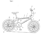
- Figure 1 shows a BMX bicycle that comprises a frame 1 composed of a diamond-shaped frame body 2 and a front fork 3, a handle component 4, a driver unit 5, a front wheel 6, a rear wheel 7 provided with a two-speed internal shifter hub 10, and a cantilever-shaped sidepull rear brake device 9 for braking the rear wheel 7.
- Components such as a saddle 11, the handle component 4, the front wheel 6, and the rear wheel 7 are mounted on the frame 1.
- the handle component 4 has a handle stem 14 that is fixed to the top of the front fork 3, and a handlebar 15 that is fixed to the handle stem 14.
- a brake lever 16 and a grip 17, which constitute the rear brake device 9, are mounted on the right end of the handlebar 15.
- the driver unit 5 comprises a chainwheel 18 mounted in the lower portion (bottom bracket) of the frame body 2, a chain 19 wound around the chainwheel 18, and an internal shifter hub 10 equipped with a sprocket 20.
- the internal shifter hub 10 is a two-step hub that includes downshifted and direct-coupled power transmission paths.
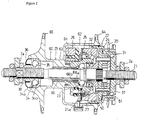
- This internal shifter hub 10 is mounted between a couple of rear fork ends 2a of the bicycle frame body 2, as shown in Figure 2.
- the internal shifter hub 10 comprises a hub axle 21 fixed in the rear fork ends 2a, a driver 22 mounted around the outside on one end of the hub axle 21 while allowed to move in a circle about the hub axle, a slave 23 that is disposed farther outward around the outside of the hub axle 21 and the driver 22 and that is linked to the rear wheel 7, a planetary gear mechanism 24 disposed around the inside of the driver 22, a clutch mechanism 25 for linking and disengaging the driver 22 and the slave 23, a clutch-switching mechanism 26 for switching the clutch mechanism 25, and a one-way clutch mechanism 27 for transmitting rotation in the travelling direction alone from the planetary gear mechanism 24 to the slave 23.
- the right end of the driver 22 ( Figure 2) is rotatably supported by a bearing component 31 on the hub axle 21, and the left end is rotatably supported by a bearing component 32 in the slave 23.
- the two ends of the slave 23 are rotatably supported by bearing components 33 and 34 on the hub axle 21.
- the hub axle 21 is a member that is fixed to the rear fork ends 2a of the bicycle frame body 2. Threaded portions for fixing or otherwise securing the axle in the rear fork ends 2a are formed on both ends of the hub axle 21.
- a large-diameter portion 21a is formed on the hub axle 21 to the right (in Figure 2) of the central section, and the sun gear 50 of the planetary gear mechanism 24 is formed on the right side of the large-diameter portion 21a.
- Hub cone members 37 and 38 having arm-shaped hub cone surfaces 31a and 34a for the bearing components 31 and 34, respectively, are screwed onto the mounting portions of the hub axle 21 that lie inward in relation to the rear fork ends 2a.
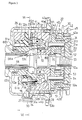
- the driver 22 is a member for transmitting the rotation of the sprocket 20. As shown in Figure 3, the driver 22 comprises a first cylindrical component 40 (the right end of this component is rotatably supported by the bearing component 31), and a second cylindrical component 41 that is non-rotatably linked to the first cylindrical component 40 (the left end of the second cylindrical component is rotatably supported by the bearing component 32).
- the first cylindrical component 40 comprises a small-diameter portion 42 on the right side of Figure 3, and a large-diameter portion 43 that is flared on the left side of the small-diameter portion 42.
- a housing space 44 for accommodating the planetary gear mechanism 24 is formed inside the first cylindrical component 40.
- the outer circumferential surface at the end of the small-diameter portion 42 is provided with an external thread 42a, and a lock nut 45 for fixing the sprocket 20 is screwed thereon.
- a sprocket attachment section 42b composed of outer serrations is formed on the outer circumferential surface of the small-diameter portion 42 in proximity to the external thread 42a, with the sprocket 20 non-rotatably attached.
- the inner-tooth gear 51 of the planetary gear mechanism 24 is formed on the inner circumferential surface of the small-diameter portion 42 on the side that faces the large-diameter portion 43.
- An arm-shaped ball race surface 31b for the bearing component 31 is formed on the inner circumferential surface at the end of the small-diameter portion 42.
- the bearing component 31 comprises the ball race surface 31b, the hub cone surface 31a, and a plurality of balls 31c interposed between the ball race surface 31b and the hub cone surface 31a.
- An internal thread 43a which is formed on the inner circumferential surface at the end of the large-diameter portion 43, is screwed onto an external thread 41a formed on the end face of the second cylindrical component 41, non-rotatably linking the second cylindrical component 41.
- a seal ring 28 for sealing the gap formed by the slave 23 is fitted over the outer circumferential surface of the large-diameter portion 43.
- the second cylindrical component 41 is a member whose diameter is smaller than that of the first cylindrical component 40 in threaded engagement with the inner circumferential surface of the first cylindrical component.
- the external thread 41a to be threadably connected with the internal thread 43a is formed on the outer circumferential surface of the end section.
- a stop 41b that rests against the tip of the large-diameter portion 43 of the first cylindrical component 40 in proximity to the external thread 41a is formed in the outer circumferential surface of the second cylindrical component 41.
- the outside diameter of the stop 41b is essentially the same size as the outside diameter of the large-diameter portion 43 of the first cylindrical component 40.
- the bearing component 32 and the clutch mechanism 25 are disposed around the inside of the second cylindrical component 41.
- the bearing component 32 comprises the ball race surface 32b, a hub cone surface 32a formed on the outer circumferential surface at the end of a power transmitting body 61 (see below) for the slave 23, and a plurality of balls 32c interposed between the ball race surface 32b and the hub cone surface 32a.
- Forming the driver 22 in such a manner into a two-part structure composed of the first cylindrical component 40 and second cylindrical component 41 makes it possible to mount the planetary gear mechanism 24 alongside the hub axle 21 without increasing the outside diameter of the section composed of the second cylindrical component 41 in comparison with the outside diameter of the section composed of the first cylindrical component 40 even when a bearing component 32 is provided.
- the outside diameter of the entire hub can therefore be reduced.
- the slave 23 is a cylindrical member driven by the driver 22 and designed for rotating the rear wheel 7.
- the slave 23 comprises a hub shell 60 that is partially disposed around the outside of the driver 22, and a power transmitting body 61 that is fastened to the hub shell 60 by a fixing bolt 66 and that is disposed around the inside of the driver 22.
- This power transmitting body 61 in addition to functioning as a body for transmitting power from the driver 22 or the planetary gear mechanism 24 to the hub shell 60, also functions as a weight support for the clutch-switching mechanism 26 described below.
- the hub shell 60 which may be a cylindrical member made of aluminum, has a large-diameter mechanism housing 62 for accommodating the driver 22, the clutch-switching mechanism 26, and the like, and a small-diameter, narrow cylindrical component 63 formed integrally with the mechanism housing 62.
- Hub flanges 64 and 65 for securing the spokes (not shown) of the rear wheel 7 are integrally formed on the outer circumferential surfaces of the mechanism housing 62 and narrow cylindrical component 63.
- the right end of the narrow cylindrical component 63 is provided with outer serrations 63a for non-rotatably securing the power transmitting body 61, and the inner circumferential surface is provided with an internal thread 63b for the threaded engagement of the fixing bolt 66.
- a space for accommodating the bearing component 34 is formed in the left end ( Figure 2) of the narrow cylindrical component 63, and a ball race member 35 provided with a ball race surface 34b (which is an element of the bearing component 34) is secured in this space.
- the bearing component 34 comprises the hub cone surface 34a, the ball race surface 34b, and a plurality of balls 34c interposed between the ball race surface 34b and the hub cone surface 34a.
- a dust cap 36 is fitted over the bearing component 34.
- the power transmitting body 61 may be a stepped cylindrical member made of chromium-molybdenum steel. As shown in Figure 3, inner serrations 61a for meshing with the outer serrations 63a of the narrow cylindrical component 63 are formed on the inner circumferential surface of the left end.
- the hub cone surface 32a for the bearing component 32 is formed on the outer circumferential surface at the right end of the power transmitting body 61, and ratchet teeth 80 constituting part of the one-way clutch mechanism 27 are formed on the inner circumferential surface of the right end.
- a ball race surface 33b for the bearing component 33 is formed on the inner circumferential surface in proximity to the ratchet teeth 80.
- the bearing component 33 comprises the ball race surface 33b, a hub cone surface 33a formed in the shape of an arm on the left end of the large-diameter portion 21a of the hub axle 21, and a plurality of balls 33c interposed between the hub cone surface 33a and the ball race surface 33b.
- a tapered section 61b is formed on the inner circumferential surface of the power transmitting body 61 in proximity to the section constituting the ball race surface 33b.
- the fixing bolt 66 is a hollow cylindrical bolt, and the hub shell 60 and the power transmitting body 61 are firmly fastened in a concentric fashion.
- the head 66a of the fixing bolt 66 is provided with a tapered surface 66b for interlocking with the tapered section 61b, allowing the power transmitting body 61 and the hub shell 60 to be aligned and fastened.
- the planetary gear mechanism 24 comprises the sun gear 50 formed on the hub axle 21, the inner-tooth gear 51 formed on the small-diameter portion 42 of the first cylindrical component 40 of the driver 22, a carrier 52 rotatably mounted on the large-diameter portion 21a of the hub axle 21, and three planetary gears 53 rotatably supported on the carrier 52.
- the carrier 52 is a member shaped as a collar flange with the hub axle 21 passing through it; and three gear housings 52a spaced at regular intervals in the circumferential direction are formed on the outer circumferential surface of this member.
- Three gear axles 54 for rotatably supporting the planetary gears 53 are fixed to the carrier 52.
- the planetary gears 53 have a small-diameter first gear element 53a for meshing with the inner-tooth gear 51, and a large-diameter second gear element 53b for meshing with the sun gear 50.
- the first gear element 53a and the second gear element 53b are formed adjacent to each other in the axial direction.
- the planetary gears 53 are thus composed of two gear elements 53a and 53b, making it possible to obtain a gear ratio corresponding to a cross ratio with a smaller number of teeth on the inner-tooth gear than in the case of a single gear element.
- the gear ratio G R is 0.891, and a single turn of the driver 22 is transmitted to the slave 23 after being reduced in speed to 0.891 revolutions.
- the gear ratio of the planetary gear mechanism 24 should fall within a range of 0.8-0.95. In this case, the start dash can be accelerated, and the outside diameter of the internal shifter hub 10 reduced even when downshifting is performed at a cross ratio.
- the gear ratio G R can be expressed by the following equation when downshifting is performed with the aid of planetary gears consisting of a single gear element.
- G R 1 / 1 + Z s / Z r
- the gear ratio G R is determined solely by the number of teeth Z r on the inner-tooth gear and the number of teeth Z s on the outer-tooth gear.
- Let us solve the equation 0.891 1/(1 + (15/Z r )) in an attempt to obtain a gear ratio of 0.891 with the aforementioned cross ratio by assuming that the number of teeth Z s on the sun gear is 15.
- the number of teeth Z r on the inner-tooth gear is 123, and the outside diameter of the driver 22 is increased at least twofold in comparison with a case in which the gear has two gear elements.
- the clutch mechanism 25 has ratchet teeth 70 (which are formed on the inner circumferential surface of the second cylindrical component 41 of the driver 22), two clutch pawls 71 capable of meshing with the ratchet teeth 70, and a spring member 72 for energizing the clutch pawls 71.
- the ratchet teeth 70 are formed as sawteeth on the inner circumferential surface of the second cylindrical component 41.
- the clutch pawls 71 are mounted on the outer circumferential surface of the power transmitting body 61 while allowed to alternate between a linked state in which they mesh with the ratchet teeth 70, and a disengaged state in which they are separated from the ratchet teeth 70.
- Pawl housings 73 for accommodating the clutch pawls 71 are provided at two positions on the outer circumferential surface of the power transmitting body 61.
- the spring member 72 which is positioned in a wound state in a groove 74 formed in the outer circumferential surface of the power transmitting body 61, pushes the clutch pawls 71 into a linked state. It is only when the clutch pawls 71 are in a linked state and the driver 22 rotates in the travelling direction that the rotation of the clutch mechanism 25 is transmitted to the power transmitting body 61 of the slave 23.
- the clutch-switching mechanism 26 comprises a control plate 75 for switching the clutch pawls 71 between a linked state and a disengaged state, a moving mechanism 76 for moving the control plate 75 in a reciprocating fashion about the hub axle, and a weight support doubling as the power transmitting body 61.
- control plate 75 is a flat member shaped as a modified ring and rotatably supported in its central portion by the power transmitting body 61.
- a hook 75a extending radially outward is formed on the outer edge of the control plate 75.
- two control windows 75b for controlling the clutch pawls 71 are formed between the inner and outer circumferences.
- the clutch pawls 71 are disposed such that they extend from the control windows 75b in the direction of the moving mechanism 76.
- the control windows 75b are provided with disengaging frames 75d for holding the clutch pawls 71 in a disengaged state, and with linking frames 75e for switching the pawls to a linked state.
- the clutch pawls 71 energized by the spring member 72 can be raised into a linked state by shaping the linking frames 75e such that they extend radially outward from the disengaging frames 75d.
- the hook 75a, the control windows 75b, and all the other components are set apart 180 degrees from each other (depending on the number of elements) to achieve balanced rotation.
- two through holes 75c accommodating the rocking axles 87 of weight retainers 85 (see below) are formed between the inner and outer circumferences.
- the control plate 75 is normally held in a disengaged position (shown in Figures 6 and 7) by the spring mechanism 79 described below. At this time, the tips of the clutch pawls 71 are stopped by the disengaging frames 75d of the control windows 75b, and the pawls are held in a disengaged state.
- the moving mechanism 76 which is disposed on the left side of the control plate 75, comprises two rocking weight members 77, links 78 for linking the two respective weight members 77 and the control plate 75, and a spring mechanism 79 for energizing the control plate 75 clockwise in Figure 6.
- the weight members 77 comprise two weight retainers 85 swingably mounted on the end face 61c of the power transmitting body 61, and weights 86 mounted on the tips of the weight retainers 85.
- the two weight retainers 85 may be made of a polyacetal resin.
- the weight retainers 85 are formed such that they form a curve around the power transmitting body 61, and are positioned in the same way 180 degrees apart from each other around the power transmitting body 61.
- Bosses 85a are formed integrally with the bases of the weight retainers 85, and weight mounting components 85b composed of two protruding pins are formed integrally with the tips of the weight retainers.
- the rocking axles 87 pass through the bosses 85a.
- the rocking axles 87 also pass via the through holes 75c, and the tips of these axles are fixed to the power transmitting body 61.
- link pins 85d are formed integrally with the tips of the weight retainers 85 on the sides opposite from the weight mounting components 85b. The link pins 85d are used for the rotatable mounting of the links 78.
- the weights 86 which may be fan-shaped members made of lead or steel, are fixed by the two pins of weight mounting components 85c.
- the links 78 are members for rotating the braking member 75 in response to the movement of the tips of the weight members 78, which are swung by the bases.
- the control plate 75 and the tips of the weight retainers 85 are linked to the two ends of these links.
- the links 78 are flat members made of metal. One end of each link is provided with a round hole for inserting the link pins 85d, and the other end is provided with a round hole for inserting a link pin 78a, which is used to achieve linkage with the braking plate 75.
- the spring mechanism 79 has a coil spring 88, one end of which is secured to the hook 75a, and a spring force adjustment mechanism 89 for adjusting the spring force of the coil spring 88.
- Shift timing can be adjusted by adjusting the spring force of the coil spring 88.
- the shift timing can also be varied by replacing the weights 86.
- the one-way clutch 27 which may be a pawl type, comprises ratchet teeth 80 formed on the inner circumferential surface of the power transmitting body 61, clutch pawls 81 mounted on the outer circumferential surface of the carrier 52 of the planetary gear mechanism 24 while allowed to alternate between a linked state and a disengaged state, and a spring member (not shown) for energizing the clutch pawls 81 into a linked state.
- the clutch pawls 81 are normally raised into a linked state, and the rotation of the carrier 52 is transmitted to the power transmitting body 61 when this carrier rotates in the travelling direction. No rotation is transmitted when the power transmitting body 61 rotates in the travelling direction at a higher speed than does the carrier 52.
- the internal shifter hub 10 has the following paths because of the presence of such a planetary gear mechanism 24, clutch mechanism 25, clutch-switching mechanism 26, and one-way clutch 27:
- the weight members 77 swing outward against the action of the energizing force exerted by the coil spring 88 of the control plate 75 when the power transmitting body 61 achieves a rotational speed above a certain level. This level is determined by the adjustment of the spring mechanism 79, the mass of the weights, or the like.
- the control plate 75 is rotated counterclockwise in Figure 8 through the intermediary of the links 78 until it reaches a linked position.
- the number of weight members or clutch pawls is not limited to two.
- One member or pawl can also be used, as can three or more members or pawls.
- they should be arranged at regular intervals according to their number.
- there are three weight members 77 they should be arranged in the same way 120 degrees apart from each other about the hub axle, as shown in Figure 10a.
- a single clutch pawl 71 can be used, as can a plurality of such pawls.
- the weight members 77 swing outward when the rotational speed has exceeded a certain limit (as shown in Figure 10b), the control plate 75 is rotated through the intermediary of the links 78, and the clutch pawls 71 rise to a linked state from the disengaged state.
- the centrifugal force increases with an increase in the number of weight members 77, and the braking plate 75 rotates with more stability.
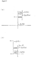
- the driver 22 should be linked to the carrier 52, and power should be transmitted from the carrier 52 to the inner-tooth gear 51, as shown in Figure 4b.
- a high gear ratio can be obtained with an inner-tooth gear whose outside diameter is less than that of a single gear element if the second gear element 53b (which, of the two gear elements 53a and 53b, has the larger diameter) is caused to mesh with the inner-tooth gear 51, and the small-diameter first gear element 53a is caused to mesh with the sun gear 50.
- the carrier 52 and the driver 22 should be linked together with the aid of the structure shown in Figure 4a if the goal is to obtain an upshifted ratio corresponding to a cross ratio.
Landscapes
- Engineering & Computer Science (AREA)
- Chemical & Material Sciences (AREA)
- Combustion & Propulsion (AREA)
- Transportation (AREA)
- Mechanical Engineering (AREA)
- Structure Of Transmissions (AREA)
- Retarders (AREA)
- Transmission Devices (AREA)
Description
- The present invention relates to a shifter hub, and more particularly to an internal bicycle shifter hub for changing the speed of rotation of an input unit and transmitting the result to an output unit.
- Small bicycles (referred to as "BMX") having 20-inch wheels are used in off-road motocross racing. In such BMX bicycles, the rear wheel is commonly driven at a fixed gear ratio of about 43 teeth on the chainwheel and about 16 teeth on the rear-wheel hub cog.
- A fast start dash is an important element of BMX motocross racing. Downshifting to a slightly lighter gear ratio than during normal riding is recommended during start-up in order to achieve higher start-up acceleration. For this reason, BMX bicycles used in motocross racing are equipped with an external shifter (comprising a rear derailleur and a hub cog having two cross-ratio sprockets) and a shifting lever linked by a cable to the rear derailleur.
- Installing an external shifter, however, makes it necessary for the rider to control this shifter by operating a shifting lever. Since BMX motocross racing involves navigating a course having a succession of small bumps and curves, the rider is busy steering and does not have much time for shifting. Consequently, it is very difficult to shift gears during a race.
- In view of this, it is possible to adopt an approach whereby the rear wheel is equipped with an internal shifter hub, and the gears are shifted automatically by changing the speed of the internal shifter hub in accordance with the bicycle speed. Such an internal shifter hub comprises a hub axle, a driver capable of rotating about the hub axle, a hub shell, a planetary gear mechanism for changing the speed of rotation of the driver and transmitting the result to the hub shell, a clutch mechanism for transmitting the output of the planetary gear mechanism to the hub shell or stopping such transmission, and a clutch-switching mechanism for switching the clutch mechanism by centrifugal force, for example.
- Bearing components are provided between one end of the driver and the hub axle, between one end of the hub shell and the other end of the driver, and between the other end of the hub shell and the hub axle, allowing the driver and the hub shell to rotate about the hub axle. The planetary gear mechanism comprises an inner-tooth gear, a sun gear, a plurality of planetary gears for meshing with the inner-tooth gear and the sun gear, and a carrier for supporting the plurality of planetary gears. The clutch-switching mechanism switches the clutch mechanism between a linked state and a disengaged state through the agency of a centrifugal force created by the rotation of the hub shell. Example of such internal shifter hubs can be seen in DE 4229023A, US 2747708, DE 1150592 and US 4973297.
- When the gear ratio of an internal shifter hub thus constructed is lowered a cross ratio is achieved (that is, when the rotation of the hub shell remains mostly unchanged in relation to the rotation of the driver), the number of teeth of the inner-tooth gear must be fairly high in relation to the number of teeth of the sun gear. Consequently, the gap between the inner-tooth gear and the sun gear is increased, as is the outside diameter of the planetary gears.
- In addition, the outside diameters of the planetary gears are sometimes increased when the gear ratio is raised. When, for example, a planetary gear consists of two gear elements (a large element and a small element), the sun gear is caused to mesh with the small gear element, and the inner-tooth gear is caused to mesh with the large gear element, then raising the gear ratio increases the outside diameter of the large gear element.
- The outside diameter of the driver increases when the outside diameters of the planetary gears are increased in such a manner. (This applies when, for example, an inner-tooth gear is formed on the inner circumferential surface of the driver, and a downshift is performed by inputting motive force from the inner-tooth gear and providing an output from a carrier via the planetary gears.) Increasing the outside diameter of the driver results in a further increase in the outside diameter of at least one of the bearing components provided at the two ends of the driver in order to support this driver because a planetary gear mechanism can be mounted inside in the axial direction. The outside diameter of the internal shifter hub increases as a result.
- An object of the present invention, therefore, is to reduce the outside diameter of the entire assembly even when the planetary gears have large outside diameters.
- The present invention is directed to a bicycle hub transmission in accordance with Claim 1. A preferred embodiment comprises a hub axle, a driver, and a planetary gear mechanism. The hub axle is an axle that can be fixed on a bicycle frame. The driver is a member which has a first cylindrical body linkable to the input unit and a second cylindrical body linked non-rotatably in relation to the first cylindrical body, in which a housing space is provided inside at least one of the two cylindrical bodies, and which is allowed to rotate about the hub axle. The slave is a member that is disposed at least partially around the inside of the second cylindrical body, that is allowed to rotate about the hub axle, and that is linkable to the output unit. The planetary gear mechanism is a mechanism that is disposed in the housing space and that is designed to change the speed of the motive power from the driver and transmitting the result to the slave.
- With the internal shifter hub, the rotation of the input unit is transmitted to the slave from the driver via the planetary gear mechanism, changing the speed of the slave. This driver has a first cylindrical body and a second cylindrical body, and the planetary shifting mechanism is disposed in the housing space of one of the cylindrical bodies but not in the other. As a result, a driver whose outside diameter is less than that of one of the cylindrical bodies having housing spaces can be obtained by providing each of the cylindrical bodies with small-diameter bearing components for supporting the driver. Consequently, the outside diameter of the entire internal shifter hub can be reduced even when the housing space of the driver accommodates a planetary gear mechanism having planetary gears of large outside diameter.
- Preferably, the outside diameter of one of the first cylindrical body and second cylindrical body is equal to or less than the outside diameter of the other cylindrical body. Because in this case the outside diameter of one of the cylindrical bodies does not exceed the outside diameter of the other cylindrical body even when the former accommodates a planetary gear mechanism, the driver has a small outside diameter, making it possible for the internal shifter hub to remain small in terms of outside diameter.
- Preferably, the first cylindrical body has an input unit fitting point for non-rotatable attachment of the input unit to the outer circumferential surface. In this case, it is possible, for example, to detachably mount an input unit such as a sprocket on the outer circumferential surface of the first cylindrical body.
- Preferably, the ball races for allowing rotation about the hub axle are provided to the inner circumferential surfaces of the first cylindrical body and second cylindrical body. In this case, bearing components can be easily provided to the corresponding cylindrical bodies of the driver.
- Preferably, the first cylindrical body and second cylindrical body are threadably joined with the aid of an internal/external thread in a mutually non-rotatable fashion. In this case, the two cylindrical bodies can be easily linked by a threaded joint.
- Alternatively, the first cylindrical body and second cylindrical body can be easily joined by a serration joint in a non-rotatable fashion.
- Preferably, either of the first and second cylindrical bodies has a stop that rests against the tip of the other cylindrical body. In this case, the two cylindrical bodies can be positioned in the axial direction with higher accuracy.
- Preferably, the planetary gear mechanism comprises an inner-tooth gear disposed on the inner circumferential surface of the first cylindrical body; a sun gear provided to the outer circumferential surface of the hub axle; one or more planetary gears for meshing with the inner-tooth gear and sun gear; and a frame body that is allowed to rotate about the hub axle, that is designed to rotatably support the planetary gears, and that is coupled with the slave; the rotation of the driver being reduced in speed and transmitted to the slave. In this case, the outside diameter of the driver is not increased over that of the first cylindrical body, and the internal shifter hub can remain small in terms of outside diameter even when the speed of rotation of the driver is reduced at a low gear ratio.
- Preferably, the planetary gear comprises a small-diameter first gear element for meshing with the inner-tooth gear, and a large-diameter second gear element that is disposed concentrically with, and in proximity to, the axial direction of the first gear element, and that is designed to mesh with the sun gear. In this case, the gear ratio of the planetary gear mechanism can be further lowered without increasing the outside diameter of the inner-tooth gear.
- Preferably, the first cylindrical body comprises a large-diameter portion that is linked to the second cylindrical body and that accommodates the second gear element of the planetary gears, and a small-diameter portion which accommodates the first gear element and in which the inner-tooth gear is formed on the inner circumferential surface. In this case, the outside diameter of the input unit can be reduced by attaching the input unit to the outer circumferential surface of the small-diameter portion of the second cylindrical body.
- Preferably, the present invention further comprises a clutch mechanism capable of linking and disengaging the slave and the second cylindrical body, and a clutch-switching mechanism for switching the clutch mechanism between a linked state and a disengaged state. In this case, the rotation of the input unit is transmitted unchanged to the output unit via the driver and the slave when the clutch mechanism is switched by the clutch-switching mechanism, and the slave and the second cylindrical body are linked. When the clutch disengages the slave and the second cylindrical body, the rotation of the input unit is inputted from the driver to the planetary gear mechanism, the speed is reduced through the intermediary of the slave and the frame body, and the result is transmitted to the output unit. Here, the output unit can be rotated at two speeds (direct coupling and reduced speed) by switching the clutch mechanism with the aid of the clutch-switching mechanism.
- Preferably, the clutch-switching mechanism switches the clutch mechanism from the disengaged state to the linked state through the intermediary of centrifugal force. In this case, the clutch mechanism is in a disengaged state when the rider steps on the pedals during startup, and the rotation of the input unit is transmitted to the output unit at a reduced speed via a planetary downshifting mechanism. The clutch mechanism is switched from the disengaged state to a linked state, the driver and the slave are directly coupled, and the rotation of the input unit is transmitted unchanged to the output unit when the bicycle speed rises above a prescribed level, and a prescribed centrifugal force is exerted on the clutch-switching mechanism. It is therefore possible to achieve an automatic upshift and to execute the desired start dash without performing any shifting operations.
-
- Figure 1 shows a side view of a bicycle according to a first embodiment of the present invention.
- Figure 2 shows a longitudinal section of an internal shifter hub according to the present invention.
- Figure 3 shows a fragmentary cross section of an internal shifter hub according to the present invention.
- Figures 4a and 4b show schematic drawings of a planetary gear mechanism.
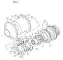
- Figure 5 shows an exploded perspective view of an internal shifter hub according to the present invention.
- Figure 6 shows cross section VI-VI of Figure 3 with the clutch in a disengaged state.
- Figure 7 shows a front view of a control plate, with the clutch in a disengaged state.
- Figure 8 shows cross section VI-VI of Figure 3 with the clutch in a linked state.
- Figure 9 shows a front view of the control plate, with the clutch in a linked state.
- Figure 10a shows cross section VI-VI of Figure 3 with the clutch in a disengaged state, according to other embodiments of the present invention.
- Figure 10b shows cross section VI-VI of Figure 3 with the clutch in a linked state, according to other embodiments of the present invention.
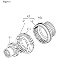
- Figure 11 shows an exploded perspective view of an internal shifter hub according to another embodiment of the present invention.
- Figure 1 shows a BMX bicycle that comprises a frame 1 composed of a diamond-shaped
frame body 2 and a front fork 3, ahandle component 4, a driver unit 5, afront wheel 6, arear wheel 7 provided with a two-speedinternal shifter hub 10, and a cantilever-shaped sidepull rear brake device 9 for braking therear wheel 7. - Components such as a saddle 11, the
handle component 4, thefront wheel 6, and therear wheel 7 are mounted on the frame 1. - The
handle component 4 has a handle stem 14 that is fixed to the top of the front fork 3, and ahandlebar 15 that is fixed to the handle stem 14. Abrake lever 16 and agrip 17, which constitute the rear brake device 9, are mounted on the right end of thehandlebar 15. - The driver unit 5 comprises a
chainwheel 18 mounted in the lower portion (bottom bracket) of theframe body 2, achain 19 wound around thechainwheel 18, and aninternal shifter hub 10 equipped with asprocket 20. - The
internal shifter hub 10 is a two-step hub that includes downshifted and direct-coupled power transmission paths. Thisinternal shifter hub 10 is mounted between a couple of rear fork ends 2a of thebicycle frame body 2, as shown in Figure 2. Theinternal shifter hub 10 comprises ahub axle 21 fixed in the rear fork ends 2a, adriver 22 mounted around the outside on one end of thehub axle 21 while allowed to move in a circle about the hub axle, aslave 23 that is disposed farther outward around the outside of thehub axle 21 and thedriver 22 and that is linked to therear wheel 7, aplanetary gear mechanism 24 disposed around the inside of thedriver 22, aclutch mechanism 25 for linking and disengaging thedriver 22 and theslave 23, a clutch-switchingmechanism 26 for switching theclutch mechanism 25, and a one-wayclutch mechanism 27 for transmitting rotation in the travelling direction alone from theplanetary gear mechanism 24 to theslave 23. The right end of the driver 22 (Figure 2) is rotatably supported by a bearingcomponent 31 on thehub axle 21, and the left end is rotatably supported by a bearingcomponent 32 in theslave 23. The two ends of theslave 23 are rotatably supported by bearingcomponents hub axle 21. - The
hub axle 21 is a member that is fixed to the rear fork ends 2a of thebicycle frame body 2. Threaded portions for fixing or otherwise securing the axle in the rear fork ends 2a are formed on both ends of thehub axle 21. A large-diameter portion 21a is formed on thehub axle 21 to the right (in Figure 2) of the central section, and thesun gear 50 of theplanetary gear mechanism 24 is formed on the right side of the large-diameter portion 21a.Hub cone members components hub axle 21 that lie inward in relation to the rear fork ends 2a. - The
driver 22 is a member for transmitting the rotation of thesprocket 20. As shown in Figure 3, thedriver 22 comprises a first cylindrical component 40 (the right end of this component is rotatably supported by the bearing component 31), and a secondcylindrical component 41 that is non-rotatably linked to the first cylindrical component 40 (the left end of the second cylindrical component is rotatably supported by the bearing component 32). - The first
cylindrical component 40 comprises a small-diameter portion 42 on the right side of Figure 3, and a large-diameter portion 43 that is flared on the left side of the small-diameter portion 42. Ahousing space 44 for accommodating theplanetary gear mechanism 24 is formed inside the firstcylindrical component 40. The outer circumferential surface at the end of the small-diameter portion 42 is provided with an external thread 42a, and alock nut 45 for fixing thesprocket 20 is screwed thereon. A sprocket attachment section 42b composed of outer serrations is formed on the outer circumferential surface of the small-diameter portion 42 in proximity to the external thread 42a, with thesprocket 20 non-rotatably attached. The inner-tooth gear 51 of theplanetary gear mechanism 24 is formed on the inner circumferential surface of the small-diameter portion 42 on the side that faces the large-diameter portion 43. An arm-shaped ball race surface 31b for thebearing component 31 is formed on the inner circumferential surface at the end of the small-diameter portion 42. The bearingcomponent 31 comprises the ball race surface 31b, thehub cone surface 31a, and a plurality ofballs 31c interposed between the ball race surface 31b and thehub cone surface 31a. - An internal thread 43a, which is formed on the inner circumferential surface at the end of the large-
diameter portion 43, is screwed onto anexternal thread 41a formed on the end face of the secondcylindrical component 41, non-rotatably linking the secondcylindrical component 41. Aseal ring 28 for sealing the gap formed by theslave 23 is fitted over the outer circumferential surface of the large-diameter portion 43. - The second
cylindrical component 41 is a member whose diameter is smaller than that of the firstcylindrical component 40 in threaded engagement with the inner circumferential surface of the first cylindrical component. Theexternal thread 41a to be threadably connected with the internal thread 43a is formed on the outer circumferential surface of the end section. Astop 41b that rests against the tip of the large-diameter portion 43 of the firstcylindrical component 40 in proximity to theexternal thread 41a is formed in the outer circumferential surface of the secondcylindrical component 41. The outside diameter of thestop 41b is essentially the same size as the outside diameter of the large-diameter portion 43 of the firstcylindrical component 40. The bearingcomponent 32 and theclutch mechanism 25 are disposed around the inside of the secondcylindrical component 41. For this reason, the ball race surface 32b of the bearingcomponent 32 and theratchet teeth 70 of theclutch mechanism 25 are formed on the inner circumferential surface of the secondcylindrical component 41. The bearingcomponent 32 comprises the ball race surface 32b, a hub cone surface 32a formed on the outer circumferential surface at the end of a power transmitting body 61 (see below) for theslave 23, and a plurality of balls 32c interposed between the ball race surface 32b and the hub cone surface 32a. - Forming the
driver 22 in such a manner into a two-part structure composed of the firstcylindrical component 40 and secondcylindrical component 41 makes it possible to mount theplanetary gear mechanism 24 alongside thehub axle 21 without increasing the outside diameter of the section composed of the secondcylindrical component 41 in comparison with the outside diameter of the section composed of the firstcylindrical component 40 even when abearing component 32 is provided. The outside diameter of the entire hub can therefore be reduced. - As shown in Figure 2, the
slave 23 is a cylindrical member driven by thedriver 22 and designed for rotating therear wheel 7. Theslave 23 comprises ahub shell 60 that is partially disposed around the outside of thedriver 22, and apower transmitting body 61 that is fastened to thehub shell 60 by a fixingbolt 66 and that is disposed around the inside of thedriver 22. Thispower transmitting body 61, in addition to functioning as a body for transmitting power from thedriver 22 or theplanetary gear mechanism 24 to thehub shell 60, also functions as a weight support for the clutch-switchingmechanism 26 described below. - The
hub shell 60, which may be a cylindrical member made of aluminum, has a large-diameter mechanism housing 62 for accommodating thedriver 22, the clutch-switchingmechanism 26, and the like, and a small-diameter, narrowcylindrical component 63 formed integrally with themechanism housing 62.Hub flanges rear wheel 7 are integrally formed on the outer circumferential surfaces of themechanism housing 62 and narrowcylindrical component 63. As shown in Figure 3, the right end of the narrowcylindrical component 63 is provided withouter serrations 63a for non-rotatably securing thepower transmitting body 61, and the inner circumferential surface is provided with an internal thread 63b for the threaded engagement of the fixingbolt 66. A space for accommodating thebearing component 34 is formed in the left end (Figure 2) of the narrowcylindrical component 63, and aball race member 35 provided with a ball race surface 34b (which is an element of the bearing component 34) is secured in this space. The bearingcomponent 34 comprises thehub cone surface 34a, the ball race surface 34b, and a plurality of balls 34c interposed between the ball race surface 34b and thehub cone surface 34a. Adust cap 36 is fitted over the bearingcomponent 34. - The
power transmitting body 61 may be a stepped cylindrical member made of chromium-molybdenum steel. As shown in Figure 3, inner serrations 61a for meshing with theouter serrations 63a of the narrowcylindrical component 63 are formed on the inner circumferential surface of the left end. The hub cone surface 32a for thebearing component 32 is formed on the outer circumferential surface at the right end of thepower transmitting body 61, and ratchetteeth 80 constituting part of the one-wayclutch mechanism 27 are formed on the inner circumferential surface of the right end. In addition, a ball race surface 33b for thebearing component 33 is formed on the inner circumferential surface in proximity to theratchet teeth 80. The bearingcomponent 33 comprises the ball race surface 33b, a hub cone surface 33a formed in the shape of an arm on the left end of the large-diameter portion 21a of thehub axle 21, and a plurality ofballs 33c interposed between the hub cone surface 33a and the ball race surface 33b. A tapered section 61b is formed on the inner circumferential surface of thepower transmitting body 61 in proximity to the section constituting the ball race surface 33b. - As shown in Figure 2, the fixing
bolt 66 is a hollow cylindrical bolt, and thehub shell 60 and thepower transmitting body 61 are firmly fastened in a concentric fashion. Thehead 66a of the fixingbolt 66 is provided with atapered surface 66b for interlocking with the tapered section 61b, allowing thepower transmitting body 61 and thehub shell 60 to be aligned and fastened. - As shown in Figure 3, the
planetary gear mechanism 24 comprises thesun gear 50 formed on thehub axle 21, the inner-tooth gear 51 formed on the small-diameter portion 42 of the firstcylindrical component 40 of thedriver 22, acarrier 52 rotatably mounted on the large-diameter portion 21a of thehub axle 21, and threeplanetary gears 53 rotatably supported on thecarrier 52. Thecarrier 52 is a member shaped as a collar flange with thehub axle 21 passing through it; and threegear housings 52a spaced at regular intervals in the circumferential direction are formed on the outer circumferential surface of this member. Threegear axles 54 for rotatably supporting theplanetary gears 53 are fixed to thecarrier 52. Theplanetary gears 53 have a small-diameterfirst gear element 53a for meshing with the inner-tooth gear 51, and a large-diametersecond gear element 53b for meshing with thesun gear 50. Thefirst gear element 53a and thesecond gear element 53b are formed adjacent to each other in the axial direction. Theplanetary gears 53 are thus composed of twogear elements - Here, as shown in Figure 4a, the gear ratio GR can be expressed by the following equation for a downshift in the inner-tooth gear input and carrier output:

where Zs is the number of teeth on thesun gear 50, Zr is the number of teeth on the inner-tooth gear 51, Zp1 is the number of teeth on thefirst gear element 53a of aplanetary gear 53, and Zp2 is the number of teeth on thesecond gear element 53b. - Here, the following result may be obtained if the number of teeth Zs on the sun gear is set to 15, the number of teeth Zr on the inner-tooth gear to 57, the number of teeth Zp1 on the first gear element to 28, and the number of teeth Zp2 on the second gear element to 13:

- Consequently, the gear ratio GR is 0.891, and a single turn of the
driver 22 is transmitted to theslave 23 after being reduced in speed to 0.891 revolutions. - The gear ratio of the
planetary gear mechanism 24 should fall within a range of 0.8-0.95. In this case, the start dash can be accelerated, and the outside diameter of theinternal shifter hub 10 reduced even when downshifting is performed at a cross ratio. - The gear ratio GR can be expressed by the following equation when downshifting is performed with the aid of planetary gears consisting of a single gear element.

- In this case, the gear ratio GR is determined solely by the number of teeth Zr on the inner-tooth gear and the number of teeth Zs on the outer-tooth gear. Let us solve the equation 0.891 = 1/(1 + (15/Zr)) in an attempt to obtain a gear ratio of 0.891 with the aforementioned cross ratio by assuming that the number of teeth Zs on the sun gear is 15. As a result, the number of teeth Zr on the inner-tooth gear is 123, and the outside diameter of the
driver 22 is increased at least twofold in comparison with a case in which the gear has two gear elements. - As shown in Figures 3, 5, and 6, the
clutch mechanism 25 has ratchet teeth 70 (which are formed on the inner circumferential surface of the secondcylindrical component 41 of the driver 22), twoclutch pawls 71 capable of meshing with theratchet teeth 70, and aspring member 72 for energizing theclutch pawls 71. Theratchet teeth 70 are formed as sawteeth on the inner circumferential surface of the secondcylindrical component 41. Theclutch pawls 71 are mounted on the outer circumferential surface of thepower transmitting body 61 while allowed to alternate between a linked state in which they mesh with theratchet teeth 70, and a disengaged state in which they are separated from theratchet teeth 70. Pawl housings 73 for accommodating theclutch pawls 71 are provided at two positions on the outer circumferential surface of thepower transmitting body 61. Thespring member 72, which is positioned in a wound state in agroove 74 formed in the outer circumferential surface of thepower transmitting body 61, pushes theclutch pawls 71 into a linked state. It is only when theclutch pawls 71 are in a linked state and thedriver 22 rotates in the travelling direction that the rotation of theclutch mechanism 25 is transmitted to thepower transmitting body 61 of theslave 23. - The clutch-switching
mechanism 26 comprises acontrol plate 75 for switching theclutch pawls 71 between a linked state and a disengaged state, a movingmechanism 76 for moving thecontrol plate 75 in a reciprocating fashion about the hub axle, and a weight support doubling as thepower transmitting body 61. - As shown in Figure 7, the
control plate 75 is a flat member shaped as a modified ring and rotatably supported in its central portion by thepower transmitting body 61. Ahook 75a extending radially outward is formed on the outer edge of thecontrol plate 75. In addition, twocontrol windows 75b for controlling theclutch pawls 71 are formed between the inner and outer circumferences. Theclutch pawls 71 are disposed such that they extend from thecontrol windows 75b in the direction of the movingmechanism 76. Thecontrol windows 75b are provided with disengagingframes 75d for holding theclutch pawls 71 in a disengaged state, and with linkingframes 75e for switching the pawls to a linked state. Theclutch pawls 71 energized by thespring member 72 can be raised into a linked state by shaping the linking frames 75e such that they extend radially outward from the disengagingframes 75d. Thehook 75a, thecontrol windows 75b, and all the other components are set apart 180 degrees from each other (depending on the number of elements) to achieve balanced rotation. In addition, two throughholes 75c accommodating the rockingaxles 87 of weight retainers 85 (see below) are formed between the inner and outer circumferences. Thecontrol plate 75 is normally held in a disengaged position (shown in Figures 6 and 7) by thespring mechanism 79 described below. At this time, the tips of theclutch pawls 71 are stopped by the disengaging frames 75d of thecontrol windows 75b, and the pawls are held in a disengaged state. - As shown in Figure 5, the moving
mechanism 76, which is disposed on the left side of thecontrol plate 75, comprises two rockingweight members 77,links 78 for linking the tworespective weight members 77 and thecontrol plate 75, and aspring mechanism 79 for energizing thecontrol plate 75 clockwise in Figure 6. - The
weight members 77 comprise twoweight retainers 85 swingably mounted on theend face 61c of thepower transmitting body 61, andweights 86 mounted on the tips of theweight retainers 85. The twoweight retainers 85 may be made of a polyacetal resin. The weight retainers 85 are formed such that they form a curve around thepower transmitting body 61, and are positioned in the same way 180 degrees apart from each other around thepower transmitting body 61.
Bosses 85a are formed integrally with the bases of theweight retainers 85, and weight mounting components 85b composed of two protruding pins are formed integrally with the tips of the weight retainers. The rockingaxles 87 pass through thebosses 85a. The rockingaxles 87 also pass via the throughholes 75c, and the tips of these axles are fixed to thepower transmitting body 61. In addition, link pins 85d are formed integrally with the tips of theweight retainers 85 on the sides opposite from the weight mounting components 85b. The link pins 85d are used for the rotatable mounting of thelinks 78. Theweights 86, which may be fan-shaped members made of lead or steel, are fixed by the two pins of weight mounting components 85c. - The
links 78 are members for rotating the brakingmember 75 in response to the movement of the tips of theweight members 78, which are swung by the bases. Thecontrol plate 75 and the tips of theweight retainers 85 are linked to the two ends of these links. Thelinks 78 are flat members made of metal. One end of each link is provided with a round hole for inserting the link pins 85d, and the other end is provided with a round hole for inserting alink pin 78a, which is used to achieve linkage with thebraking plate 75. - As shown in Figure 6, the
spring mechanism 79 has acoil spring 88, one end of which is secured to thehook 75a, and a springforce adjustment mechanism 89 for adjusting the spring force of thecoil spring 88. Shift timing can be adjusted by adjusting the spring force of thecoil spring 88. The shift timing can also be varied by replacing theweights 86. - As shown in Figure 6, the one-way clutch 27, which may be a pawl type, comprises ratchet
teeth 80 formed on the inner circumferential surface of thepower transmitting body 61,clutch pawls 81 mounted on the outer circumferential surface of thecarrier 52 of theplanetary gear mechanism 24 while allowed to alternate between a linked state and a disengaged state, and a spring member (not shown) for energizing theclutch pawls 81 into a linked state. In the one-way clutch 27, theclutch pawls 81 are normally raised into a linked state, and the rotation of thecarrier 52 is transmitted to thepower transmitting body 61 when this carrier rotates in the travelling direction. No rotation is transmitted when thepower transmitting body 61 rotates in the travelling direction at a higher speed than does thecarrier 52. - The
internal shifter hub 10 has the following paths because of the presence of such aplanetary gear mechanism 24,clutch mechanism 25, clutch-switchingmechanism 26, and one-way clutch 27: - a downshifted power transmission path composed of the
driver 22, inner-tooth gear 50,planetary gear mechanism 24,carrier 52, andslave 23; and a direct-coupled power transmission path composed of thedriver 22,clutch mechanism 25, andslave 23. - When the rider steps on the pedals during start-up, propelling the bicycle, the resulting rotation is transmitted to the
driver 22 via thesprocket 20. At this time, thecontrol plate 75 is in a disengaged position, and theclutch pawls 71 are held in a disengaged state by thecontrol plate 75. Consequently, there is no linkage between thedriver 22 and thepower transmitting body 61, and the rotation of thedriver 22 is transmitted to thepower transmitting body 61 along the downshifted power transmission path. As a result, the rotation of thesprocket 20 during start-up is transmitted to thehub shell 60 after being reduced in speed to 0.891, for example. It is therefore possible to lightly step on the pedals during start-up, achieving a start dash. - As shown in Figures 8 and 9, the
weight members 77 swing outward against the action of the energizing force exerted by thecoil spring 88 of thecontrol plate 75 when thepower transmitting body 61 achieves a rotational speed above a certain level. This level is determined by the adjustment of thespring mechanism 79, the mass of the weights, or the like. When theweight members 77 move in this manner, thecontrol plate 75 is rotated counterclockwise in Figure 8 through the intermediary of thelinks 78 until it reaches a linked position. When thecontrol plate 75 has reached the linked position, the linkingframes 75e of thecontrol windows 75b position themselves at the tips of theclutch pawls 71, and theclutch pawls 71 are raised into a linked state by the energizing force of thespring member 72. As a result, the rotation of thedriver 22 in the travelling direction is transmitted directly to thepower transmitting body 61 along the direct-coupled power transmission path, and the rotation of thesprocket 20 is transmitted unchanged to therear wheel 7. Consequently, an upshift is performed once the rotational speed has exceeded a certain level. There is no reduction in the transmission efficiency of theplanetary gear mechanism 24 during this regular ride because thedriver 22 and theslave 23 are coupled directly. - When the rotational speed of the
power transmitting body 61 drops below a prescribed level during cornering or the like, theweight members 77 are returned to their initial disengaged state by thecoil spring 88, and the rotation of thedriver 22 is transmitted to theslave 23 along the downshifted power transmission path. - The number of weight members or clutch pawls is not limited to two. One member or pawl can also be used, as can three or more members or pawls. When three or more members or pawls are used, they should be arranged at regular intervals according to their number. When, for example, there are three
weight members 77, they should be arranged in the same way 120 degrees apart from each other about the hub axle, as shown in Figure 10a. Furthermore, a singleclutch pawl 71 can be used, as can a plurality of such pawls. In this case, theweight members 77 swing outward when the rotational speed has exceeded a certain limit (as shown in Figure 10b), thecontrol plate 75 is rotated through the intermediary of thelinks 78, and theclutch pawls 71 rise to a linked state from the disengaged state. Thus, the centrifugal force increases with an increase in the number ofweight members 77, and thebraking plate 75 rotates with more stability. - The embodiment described above pertained to a case in which the speed was changed from direct to reduced, but a shift from a direct speed to a higher speed is also possible. In this case, the
driver 22 should be linked to thecarrier 52, and power should be transmitted from thecarrier 52 to the inner-tooth gear 51, as shown in Figure 4b. At this time, a high gear ratio can be obtained with an inner-tooth gear whose outside diameter is less than that of a single gear element if thesecond gear element 53b (which, of the twogear elements tooth gear 51, and the small-diameterfirst gear element 53a is caused to mesh with thesun gear 50. In addition, thecarrier 52 and thedriver 22 should be linked together with the aid of the structure shown in Figure 4a if the goal is to obtain an upshifted ratio corresponding to a cross ratio. - Although the embodiment described above pertained to a case in which the first
cylindrical component 40 and the secondcylindrical component 41 of thedriver 22 were fixed with the aid of a thread, it is also possible, for example, to provide the firstcylindrical component 40 and the secondcylindrical component 41 withserrations 40c and 41c, respectively, and to fix the two cylindrical components by meshing with the serrations, as shown in Figure 11.
Claims (16)
- A bicycle hub transmission comprising:a hub axle (21) ;a driver (22) rotatably mounted to the hub axle (21), wherein the driver (22) includes:characterised in that the slave (23) comprises a hub shell (60) and a power transmitting body (61), the power transmitting body (61) being at least partially disposed within the second driving member (41) and non-rotatably secured to the hub shell (60).a first driving member (40) having a smaller diameter portion (42) with a smaller diameter inner peripheral surface;a second driving member (41) axially aligned with the first driving member (40) and nonrotatably coupled to the first driving member (40), wherein the second driving member (41) has a smaller diameter portion with a smaller diameter inner peripheral surface, and wherein at least one of the first driving member (40) and the second driving member (41) has a larger diameter portion (43) with a larger diameter inner peripheral surface defining a housing space (44) axially between the smaller diameter inner peripheral surface of the first driving member (40) and the smaller diameter inner peripheral surface of the second driving member (41);a slave (23) rotatably mounted to the hub axle (21); anda power transmitting mechanism disposed at least partially in the housing space (44) for changing a rotational speed of the driver (22) and for communicating rotational power from the driver (22) to the slave (23);
- A bicycle hub transmission according to Claim 1, wherein the first driving member (40) comprises a first cylindrical body and the second driving member (41) comprises a second cylindrical body.'
- A bicycle hub transmission according to Claim 2, wherein the outside diameter of one of the first or second cylindrical bodies (40,41) is equal to or less than the outside diameter of the other cylindrical body (40,41).
- A bicycle hub transmission according to either Claim 2 or Claim 3, wherein an outer peripheral surface of the first cylindrical body (40) has an input unit fitting point (42b) for non-rotatable attachment of an input unit (20) thereto.
- A bicycle hub transmission according to any of Claims 2 to 4, wherein ball races (31,32) for allowing rotation about said hub axle (21) are provided to the inner peripheral surfaces of said first cylindrical body (40) and second cylindrical body (41).
- A bicycle hub transmission according to Claim 5, wherein one of the ball races (32) is located between the inner peripheral surface of the second cylindrical body (41) and an outer peripheral surface of the slave (23).
- A bicycle hub transmission according to any of Claims 2 to 6, wherein said first cylindrical body (40) and second cylindrical body (41) are threadably joined with the aid of an internal/external thread (41a,43a) in a mutually non-rotatable fashion.
- A bicycle hub transmission according to any of Claims 2 to 6, wherein said first cylindrical body (40) and second cylindrical body (41) are joined by a serration joint in a mutually non-rotatable fashion.
- A bicycle hub transmission according to any of Claims 2 to 8, wherein one of said first and second cylindrical bodies (41) has a stop (41b) that rests against the tip of the other cylindrical body (40).
- A bicycle hub transmission according to any of Claims 2 to 9, wherein the power transmitting mechanism comprises a planetary gear mechanism (24).
- A bicycle hub transmission according to Claim 10, wherein the planetary gear mechanism (24) comprises:an inner-tooth gear (51) disposed on the first cylindrical body (40);a sun gear (50) provided on the hub axle (21);one or more planetary gears (53) for meshing with said inner-tooth gear (51) and sun gear (50); anda frame body (52) that is allowed to rotate about said hub axle (21), that is designed to rotatably support said planetary gears (53), and that is coupled with said slave (23);the rotation of said driver (22) being reduced in speed and transmitted to said slave (23).
- A bicycle hub transmission according to Claim 11, wherein said planetary gears (53) comprise:a small-diameter first gear element (53a) for meshing with said inner-tooth gear (51); anda large-diameter second gear element (53b) that is disposed concentrically with, and in proximity to, the axial direction of said first gear element (53a), and that is designed to mesh with said sun gear (50).
- A bicycle hub transmission according to Claim 12, wherein said first cylindrical body (40) comprises a large-diameter portion (43) that accommodates the second gear element (53b) of said planetary gears (53).
- A bicycle hub transmission according to any of Claims 10 to 12, wherein the inner-tooth gear (51) is formed on the smaller diameter inner peripheral surface of the first cylindrical body (40).
- A bicycle hub transmission according to any of Claims 2 to 14, further comprising:a clutch mechanism (27) capable of linking and disengaging said slave (23) and said second cylindrical body (41); anda clutch-switching mechanism (26) for switching said clutch mechanism (27) between a linked state and a disengaged state.
- A bicycle hub transmission according to Claim 15, wherein said clutch-switching mechanism (26) switches said clutch mechanism (27) from the disengaged state to the linked state through the intermediary of centrifugal force.
Applications Claiming Priority (3)
| Application Number | Priority Date | Filing Date | Title |
|---|---|---|---|
| JP21523597 | 1997-08-08 | ||
| JP215235/97 | 1997-08-08 | ||
| JP21523597A JP3204929B2 (en) | 1997-08-08 | 1997-08-08 | Interior gear hub for bicycle |
Publications (3)
| Publication Number | Publication Date |
|---|---|
| EP0895926A2 EP0895926A2 (en) | 1999-02-10 |
| EP0895926A3 EP0895926A3 (en) | 2000-07-05 |
| EP0895926B1 true EP0895926B1 (en) | 2006-11-29 |
Family
ID=16668962
Family Applications (1)
| Application Number | Title | Priority Date | Filing Date |
|---|---|---|---|
| EP98306270A Revoked EP0895926B1 (en) | 1997-08-08 | 1998-08-05 | Hub transmission for a bicycle |
Country Status (6)
| Country | Link |
|---|---|
| US (1) | US6004240A (en) |
| EP (1) | EP0895926B1 (en) |
| JP (1) | JP3204929B2 (en) |
| CN (1) | CN1098787C (en) |
| DE (1) | DE69836521T2 (en) |
| TW (1) | TW404911B (en) |
Families Citing this family (10)
| Publication number | Priority date | Publication date | Assignee | Title |
|---|---|---|---|---|
| US6401895B1 (en) * | 2001-01-17 | 2002-06-11 | Kun Teng Industry Co., Ltd. | Freewheeling hub device for a bicycle |
| JP3501781B2 (en) † | 2001-08-01 | 2004-03-02 | 株式会社シマノ | Bicycle transmission positioning device |
| JP4221399B2 (en) * | 2005-07-29 | 2009-02-12 | 株式会社シマノ | Bicycle hub cover |
| US8888629B2 (en) * | 2007-05-23 | 2014-11-18 | Shimano Inc. | Bicycle sprocket assembly with chain protector |
| US10604213B2 (en) * | 2015-08-28 | 2020-03-31 | Advancing Technologies B.V. | Bicycle transmission for use between a chain wheel carrier and a wheel hub of a bicycle, as well as rear axle and rear wheel provided with such a transmission |
| JP6060306B1 (en) * | 2016-08-02 | 2017-01-11 | 未来のアグリ株式会社 | Animal escape facility |
| CN106542043B (en) * | 2016-12-21 | 2021-12-28 | 张家港川梭车业有限公司 | Centrifugal mechanism |
| US10633056B2 (en) * | 2017-04-12 | 2020-04-28 | Tae Hong Ha | Bicycle with automatic transmission |
| KR101874244B1 (en) * | 2017-04-12 | 2018-07-05 | 하민수 | Automatic transmission |
| KR101874245B1 (en) * | 2017-04-12 | 2018-07-05 | 하민수 | Bicycle with automatic transmission |
Family Cites Families (17)
| Publication number | Priority date | Publication date | Assignee | Title |
|---|---|---|---|---|
| DE179072C (en) * | ||||
| FR858404A (en) * | 1939-04-25 | 1940-11-25 | Freewheel hub, single or double, for bicycles and other applications | |
| NL65675C (en) | 1944-08-05 | 1900-01-01 | ||
| US2747708A (en) | 1955-02-14 | 1956-05-29 | Bendix Aviat Corp | Automatic two-speed gearing for bicycles |
| DE1150592B (en) | 1961-08-02 | 1963-06-20 | Fichtel & Sachs Ag | Two-speed transmission hub for bicycles or the like. |
| US3143005A (en) * | 1961-12-28 | 1964-08-04 | Fichtel & Sachs Ag | Multiple speed hub with automatically varying transmission ratio |
| DE1750897B2 (en) * | 1968-06-15 | 1971-07-29 | Fichtel & Sachs Ag, 8720 Schweinfurt | SELF-SHIFTING MULTIPLE SPEED HUB WITH A PLANETARY GEAR |
| DE1809141C3 (en) * | 1968-11-15 | 1979-03-22 | Fichtel & Sachs Ag, 8720 Schweinfurt | Centrifugal switch for automatically operated gear shifting, especially with multi-speed translation hubs for bicycles or the like |
| YU31884B (en) * | 1968-11-15 | 1973-12-31 | Fichtel & Sachs Ag | Spojnica predvidjena za dejstvo pomocu centrifugalne sile |
| US3803932A (en) * | 1972-07-26 | 1974-04-16 | C Waddington | Waddington drive |
| US4294138A (en) * | 1978-07-21 | 1981-10-13 | Shimano Industrial Company, Limited | Two stage transmission hub for a bicycle |
| US4276973A (en) * | 1978-09-13 | 1981-07-07 | Shimano Industrial Company, Limited | Control mechanism for a transmitting-pawl at a transmission hub for a bicycle |
| JPS59102504U (en) * | 1982-12-27 | 1984-07-10 | 株式会社シマノ | bicycle hub |
| FR2544817B1 (en) * | 1983-04-25 | 1988-08-05 | Shimano Industrial Co | FREE WHEEL FOR A BICYCLE |
| US4858494A (en) * | 1988-05-02 | 1989-08-22 | Healy Donald B | Torque responsive automatic shifting hub |
| DE3930374A1 (en) * | 1988-10-10 | 1990-04-12 | Fichtel & Sachs Ag | MULTI-SPEED DRIVE HUB WITH MORE THAN THREE GEARS |
| DE4229023C2 (en) * | 1992-09-01 | 1995-02-16 | Fichtel & Sachs Ag | Shifting device for multi-speed hub |
-
1997
- 1997-08-08 JP JP21523597A patent/JP3204929B2/en not_active Expired - Fee Related
-
1998
- 1998-07-23 TW TW087112063A patent/TW404911B/en not_active IP Right Cessation
- 1998-08-03 US US09/128,348 patent/US6004240A/en not_active Expired - Lifetime
- 1998-08-05 DE DE69836521T patent/DE69836521T2/en not_active Expired - Lifetime
- 1998-08-05 EP EP98306270A patent/EP0895926B1/en not_active Revoked
- 1998-08-07 CN CN98116221A patent/CN1098787C/en not_active Expired - Fee Related
Also Published As
| Publication number | Publication date |
|---|---|
| DE69836521D1 (en) | 2007-01-11 |
| CN1208000A (en) | 1999-02-17 |
| CN1098787C (en) | 2003-01-15 |
| EP0895926A2 (en) | 1999-02-10 |
| US6004240A (en) | 1999-12-21 |
| TW404911B (en) | 2000-09-11 |
| JPH1149073A (en) | 1999-02-23 |
| DE69836521T2 (en) | 2007-10-04 |
| JP3204929B2 (en) | 2001-09-04 |
| EP0895926A3 (en) | 2000-07-05 |
Similar Documents
| Publication | Publication Date | Title |
|---|---|---|
| US6146297A (en) | Bicycle automatic shift control device with varying shift speeds | |
| US6676549B1 (en) | Motion sensor for use with a bicycle sprocket assembly | |
| US7166054B2 (en) | Bicycle internal hub transmission with increased bearing size | |
| EP1413509B1 (en) | Bicycle hub transmission | |
| US5971884A (en) | Power changing apparatus of bicycle hub | |
| US6641500B2 (en) | Bicycle hub transmission with a power control mechanism for a shift assist mechanism | |
| US7682283B2 (en) | Bicycle hub transmission with a power control mechanism for a shift assist mechanism | |
| US6875150B2 (en) | Multiple piece planet gear carrier for a bicycle hub transmission | |
| EP0895926B1 (en) | Hub transmission for a bicycle | |
| EP0895928B1 (en) | Hub transmission for a bicycle | |
| US7083542B2 (en) | Internal bicycle hub transmission with a one-way clutch for a driving member | |
| US20060229155A1 (en) | Internally geared bicycle hub | |
| US6013005A (en) | Bicycle hub transmission with a cylindrical bolt for coupling a weight support to a hub shell | |
| US3540309A (en) | Front chain sprocket having a built-in automatic speed change mechanism | |
| US20030080529A1 (en) | Bicycle with speed change gear | |
| JPH04176788A (en) | Transmission device for bicycle | |
| WO1981000546A1 (en) | Multiple-speed cycle gear hub and cycle incorporating the same | |
| JP3112247B2 (en) | Rear wheel drive for tricycle with gearbox | |
| WO2009038466A1 (en) | Encapsulated and modular gear system | |
| MXPA97006587A (en) | Appliance to change bicycle axle power |
Legal Events
| Date | Code | Title | Description |
|---|---|---|---|
| PUAI | Public reference made under article 153(3) epc to a published international application that has entered the european phase |
Free format text: ORIGINAL CODE: 0009012 |
|
| 17P | Request for examination filed |
Effective date: 19980819 |
|
| AK | Designated contracting states |
Kind code of ref document: A2 Designated state(s): DE FR GB IT |
|
| AX | Request for extension of the european patent |
Free format text: AL;LT;LV;MK;RO;SI |
|
| PUAL | Search report despatched |
Free format text: ORIGINAL CODE: 0009013 |
|
| AK | Designated contracting states |
Kind code of ref document: A3 Designated state(s): AT BE CH CY DE DK ES FI FR GB GR IE IT LI LU MC NL PT SE |
|
| AX | Request for extension of the european patent |
Free format text: AL;LT;LV;MK;RO;SI |
|
| AKX | Designation fees paid |
Free format text: DE FR GB IT |
|
| TPAD | Observations filed by third parties |
Free format text: ORIGINAL CODE: EPIDOS TIPA |
|
| 17Q | First examination report despatched |
Effective date: 20030204 |
|
| GRAP | Despatch of communication of intention to grant a patent |
Free format text: ORIGINAL CODE: EPIDOSNIGR1 |
|
| RAP1 | Party data changed (applicant data changed or rights of an application transferred) |
Owner name: SHIMANO INC. |
|
| GRAS | Grant fee paid |
Free format text: ORIGINAL CODE: EPIDOSNIGR3 |
|
| GRAA | (expected) grant |
Free format text: ORIGINAL CODE: 0009210 |
|
| AK | Designated contracting states |
Kind code of ref document: B1 Designated state(s): DE FR GB IT |
|
| PG25 | Lapsed in a contracting state [announced via postgrant information from national office to epo] |
Ref country code: IT Free format text: LAPSE BECAUSE OF FAILURE TO SUBMIT A TRANSLATION OF THE DESCRIPTION OR TO PAY THE FEE WITHIN THE PRESCRIBED TIME-LIMIT;WARNING: LAPSES OF ITALIAN PATENTS WITH EFFECTIVE DATE BEFORE 2007 MAY HAVE OCCURRED AT ANY TIME BEFORE 2007. THE CORRECT EFFECTIVE DATE MAY BE DIFFERENT FROM THE ONE RECORDED. Effective date: 20061129 |
|
| REG | Reference to a national code |
Ref country code: GB Ref legal event code: FG4D |
|
| REF | Corresponds to: |
Ref document number: 69836521 Country of ref document: DE Date of ref document: 20070111 Kind code of ref document: P |
|
| ET | Fr: translation filed | ||
| PLBI | Opposition filed |
Free format text: ORIGINAL CODE: 0009260 |
|
| PLAX | Notice of opposition and request to file observation + time limit sent |
Free format text: ORIGINAL CODE: EPIDOSNOBS2 |
|
| PLAF | Information modified related to communication of a notice of opposition and request to file observations + time limit |
Free format text: ORIGINAL CODE: EPIDOSCOBS2 |
|
| 26 | Opposition filed |
Opponent name: SRAM DEUTSCHLAND GMBH Effective date: 20070824 |
|
| PLBB | Reply of patent proprietor to notice(s) of opposition received |
Free format text: ORIGINAL CODE: EPIDOSNOBS3 |
|
| GBPC | Gb: european patent ceased through non-payment of renewal fee |
Effective date: 20070805 |
|
| PG25 | Lapsed in a contracting state [announced via postgrant information from national office to epo] |
Ref country code: GB Free format text: LAPSE BECAUSE OF NON-PAYMENT OF DUE FEES Effective date: 20070805 |
|
| PGFP | Annual fee paid to national office [announced via postgrant information from national office to epo] |
Ref country code: FR Payment date: 20110818 Year of fee payment: 14 |
|
| REG | Reference to a national code |
Ref country code: FR Ref legal event code: ST Effective date: 20130430 |
|
| PG25 | Lapsed in a contracting state [announced via postgrant information from national office to epo] |
Ref country code: FR Free format text: LAPSE BECAUSE OF NON-PAYMENT OF DUE FEES Effective date: 20120831 |
|
| PGFP | Annual fee paid to national office [announced via postgrant information from national office to epo] |
Ref country code: DE Payment date: 20140730 Year of fee payment: 17 |
|
| RDAF | Communication despatched that patent is revoked |
Free format text: ORIGINAL CODE: EPIDOSNREV1 |
|
| REG | Reference to a national code |
Ref country code: DE Ref legal event code: R103 Ref document number: 69836521 Country of ref document: DE Ref country code: DE Ref legal event code: R064 Ref document number: 69836521 Country of ref document: DE |
|
| RDAG | Patent revoked |
Free format text: ORIGINAL CODE: 0009271 |
|
| STAA | Information on the status of an ep patent application or granted ep patent |
Free format text: STATUS: PATENT REVOKED |
|
| 27W | Patent revoked |
Effective date: 20150309 |
|
| REG | Reference to a national code |
Ref country code: DE Ref legal event code: R107 Ref document number: 69836521 Country of ref document: DE |