EP0895410B1 - Ink relocation for color halftones - Google Patents
Ink relocation for color halftones Download PDFInfo
- Publication number
- EP0895410B1 EP0895410B1 EP98305939A EP98305939A EP0895410B1 EP 0895410 B1 EP0895410 B1 EP 0895410B1 EP 98305939 A EP98305939 A EP 98305939A EP 98305939 A EP98305939 A EP 98305939A EP 0895410 B1 EP0895410 B1 EP 0895410B1
- Authority
- EP
- European Patent Office
- Prior art keywords
- color
- pixel
- brightness variation
- neighbor pair
- halftone
- Prior art date
- Legal status (The legal status is an assumption and is not a legal conclusion. Google has not performed a legal analysis and makes no representation as to the accuracy of the status listed.)
- Expired - Lifetime
Links
- 238000000034 method Methods 0.000 claims description 103
- 230000008569 process Effects 0.000 claims description 73
- 230000009467 reduction Effects 0.000 claims description 25
- 239000000976 ink Substances 0.000 description 51
- 239000003086 colorant Substances 0.000 description 31
- 238000012360 testing method Methods 0.000 description 25
- 238000012545 processing Methods 0.000 description 20
- 238000012937 correction Methods 0.000 description 19
- 239000007787 solid Substances 0.000 description 13
- 238000009877 rendering Methods 0.000 description 10
- 238000013461 design Methods 0.000 description 9
- 230000000875 corresponding effect Effects 0.000 description 8
- 238000009792 diffusion process Methods 0.000 description 8
- 230000000694 effects Effects 0.000 description 7
- 230000008859 change Effects 0.000 description 4
- 238000010586 diagram Methods 0.000 description 4
- 238000005192 partition Methods 0.000 description 4
- 238000013507 mapping Methods 0.000 description 3
- 238000012805 post-processing Methods 0.000 description 3
- 239000000047 product Substances 0.000 description 3
- 230000000007 visual effect Effects 0.000 description 3
- 239000000654 additive Substances 0.000 description 2
- 230000000996 additive effect Effects 0.000 description 2
- 238000013459 approach Methods 0.000 description 2
- 238000009125 cardiac resynchronization therapy Methods 0.000 description 2
- 230000000295 complement effect Effects 0.000 description 2
- 230000007423 decrease Effects 0.000 description 2
- 230000001419 dependent effect Effects 0.000 description 2
- 238000009499 grossing Methods 0.000 description 2
- 238000003707 image sharpening Methods 0.000 description 2
- 238000012986 modification Methods 0.000 description 2
- 230000004048 modification Effects 0.000 description 2
- 230000007935 neutral effect Effects 0.000 description 2
- 238000004321 preservation Methods 0.000 description 2
- 238000007639 printing Methods 0.000 description 2
- 229920006395 saturated elastomer Polymers 0.000 description 2
- 230000007480 spreading Effects 0.000 description 2
- 238000010521 absorption reaction Methods 0.000 description 1
- 238000007792 addition Methods 0.000 description 1
- 239000006227 byproduct Substances 0.000 description 1
- 230000002596 correlated effect Effects 0.000 description 1
- 230000003247 decreasing effect Effects 0.000 description 1
- 238000005516 engineering process Methods 0.000 description 1
- 238000003384 imaging method Methods 0.000 description 1
- 230000006872 improvement Effects 0.000 description 1
- 238000010348 incorporation Methods 0.000 description 1
- 238000007641 inkjet printing Methods 0.000 description 1
- 230000003993 interaction Effects 0.000 description 1
- 238000005259 measurement Methods 0.000 description 1
- 230000008092 positive effect Effects 0.000 description 1
- 238000005070 sampling Methods 0.000 description 1
- 230000001629 suppression Effects 0.000 description 1
- 239000011800 void material Substances 0.000 description 1
Images


Classifications
-
- H—ELECTRICITY
- H04—ELECTRIC COMMUNICATION TECHNIQUE
- H04N—PICTORIAL COMMUNICATION, e.g. TELEVISION
- H04N1/00—Scanning, transmission or reproduction of documents or the like, e.g. facsimile transmission; Details thereof
- H04N1/46—Colour picture communication systems
- H04N1/56—Processing of colour picture signals
- H04N1/58—Edge or detail enhancement; Noise or error suppression, e.g. colour misregistration correction
Definitions
- the present invention relates to digital image processing and, more particularly, to processing color halftone images.
- Monochrome halftone algorithms are carefully designed to reduce visible artifacts.
- Current color halftoning algorithms are usually a Cartesian product of three halftoned monochrome planes corresponding to the color components of the image. See, for example, A. Zakhor, S. Lin and F. Eskafi, "A New Class of B/W and Color Halftoning Algorithms", International Conference on Acoustics, Speech and Signal Processing , 1991.
- a process and apparatus is described to reduce the notice-ability of the artifact pattern of halftoned color images by a process of ink relocation.
- the Ink Relocation process transforms arbitrary color halftones to halftones conforming to the third color design criterion which is embodied in the Minimum Brightness Variation Criterion (MBVC).
- MBVC Minimum Brightness Variation Criterion
- Ink Relocation reduces halftone noise, however, it may also blur details in the image.
- we present two alternative enhancement techniques to overcome the blur The first is essentially a switch, disabling Ink Relocation near significant image details (edges).
- the second is a modification of a halftone sharpening process.
- the Ink Relocation procedure can be applied to any arbitrary color halftoned image, and can substantially improve the image quality.
- the procedure is also reasonably fast to compute.
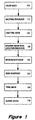
- FIG. 1 is a block diagram illustrating an apparatus for processing and displaying a color halftoned digital image using a post-processing color halftone local brightness variation reduction scheme according to the present invention.
- digital color image 100 is processed by halftoning processor 110 to yield color halftone image 120.
- Halftone processor 110 may operate using any known color halftoning technique.
- color halftone image 120 can be any arbitrary color halftone image.
- minimum brightness variation processor 130 operates on halftone image 120 to form intermediate image 140.
- edge-sharpening processor 150 operates on intermediate image 140 to yield sharpened final image 160, which is then produced by output device 170. Alternately, edge-sharpening is not performed. Instead, the intermediate image 140 is the final image 160 produced by output device 170.
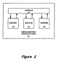
- FIG. 2 is a block diagram illustrating a post-halftoning apparatus suitable for applying color halftone local brightness variation reduction according to the present invention.
- Minimum brightness variation processor 130 includes controller 210, comparer 220, relocator 230 and suppressor 240.
- Controller 210 controls operation of the minimum brightness variation processor such that the brightness variation of adjacent pixels in the color halftone image are examined. If comparer 220 identifies a candidate pixel set wherein brightness variation can be reduced, then relocator 230 will replace the pixel values of the candidate set with pixel values having a lesser brightness variation.
- suppressor 240 will quash brightness variation reduction by relocator 230 under certain circumstances that will be explained below. Alternately, suppressor 240 is not used, and relocator 230 will operate to minimize brightness variation for any candidate pair identified by comparer 220.
- minimum brightness variation processor 130 takes for example, a solid patch of 50% Gray.
- some dot pattern e.g., checkerboard
- This pattern could be equally rendered with Black and White dots as with Blue and Yellow, Red and Cyan, or Green and Magenta dots.
- Figure 3 is a drawing illustrating the RGB cube and its main diagonals, meeting on 50% gray 310.
- the color of the halftoned patch will, theoretically, be the same in all cases.
- the noise effect however, will be different.
- Green and Magenta being almost equally bright will have a low noise effect, in contrast to, for example, Black and White.
- Section 1 we analyze this additional criterion by-examining a simple case of rendering patches of arbitrary solid color.
- the redesign of the various halftone methods with an additional color criterion deserves special treatment, and is described in U.S. Patent Application number 08/903,899, entitled “Color Halftone Error Diffusion with Local Brightness Variation Reduction", corresponding to European Patent Application number 98305938 filed on even date herewith and published under EP 895 408.
- Section 2 presents Ink Relocation, a postprocess which transforms arbitrary halftones to halftones conforming to the new color design criterion.
- Section 3 after a short discussion of some relevant color correction issues, we present two alternative enhancement routines to overcome the blur.
- the first is essentially a switch, disabling Ink Relocation near significant image details (edges).
- the second is a modification of a halftone sharpening process described in greater detail in U.S. Patent Application 08/734,821, filed October 22, 1996, A. Silverstein. Section 4, describes in detail one embodiment of Ink Relocation.
- Section 5 is a summary.
- the color design criterion for the special case of constant color patches is the minimal brightness variation criterion.
- natural images are much more complex than patches of solid color, and halftoning algorithms are carefully designed to optimally render a variety of textures and patterns.
- Each halftoning algorithm e.g., Dithering, or Error-Diffusion, uses different techniques, which interpret the same design criteria differently.
- incorporation of the additional color criterion to each of the basic halftone methods requires a separate approach.
- the secondary color used is argmax ⁇ R,G,B ⁇
- the primary color is the additive combination of the two distinct secondaries argmax ⁇ R,G,B ⁇ and argmed ⁇ R,G,B ⁇ .
- the color appearance rates in the dither quadruple are:
- the minimal brightness variation quadruple is RGBK. Otherwise proceed with the following procedures: WB ⁇ CM; WR ⁇ YM; WG ⁇ YC.
- the minimal brightness variation quadruple is WCMY. Otherwise we are left with dots of 6 colors.
- the following two procedures select between Blue and Yellow, and between Red and Cyan: BY ⁇ GM; RC ⁇ GM.
- Figures 4 A through F are drawings illustrating the partition of the RGB cube into six classes, each of which is the convex hull of the minimal brightness variation quadruple.
- the minimal brightness variation quadruple corresponding to a given color is the set of vertices of the tetrahedra in which it is located.
- RGB triplet Given an RGB triplet, one may compute its minimal brightness variation quadruple by point location. Such a computation entails (on the average) 4 additions and under 3 comparisons.
- any halftoning method renders desired colors locally, the process described in (3)-(6) may also be applied locally. Note also that all the processes involve actually no more than a relocation of a single ink layer between two locations. A dot is relocated from a multi-dot location to a location with less dots. Actually in all processes (3)-(5), dot number differences are two or three.
- Figure 5 is a drawing illustrating local brightness variation reduction through relocation of ink dots as practiced according to one embodiment of the present invention.
- the process in (3) involves a relocation of the Magenta ink drop from the location of the Black dot (a 3-dot location), to the empty location of the White dot (3 dot difference), as can be seen in Figure 5.
- Black dot 510 and White dot 520 are replaced after the post-process by Green dot 530 and Magenta dot 540, respectively.
- Black dot 510 is composed of Cyan dot 510C, Magenta dot 510M and Yellow dot 510Y
- Green dot 530 is produced by Cyan dot 530C and Yellow dot 530Y, with no Magenta dot at location 530M.
- White dot 520 is composed of no dots (i.e., no Cyan dot at location 520C, no Magenta dot at location 520M and no Yellow dot at location 520Y), whereas Magenta dot 540 is produced by Magenta dot 520M, with no Cyan dot at location 520C or Yellow dot at location 520Y.
- the Ink Relocation process can be viewed as a way of spreading ink dots from multi-dot locations to neighboring locations having fewer dots.
- this alternate view of the process is less satisfying than that of minimizing local brightness variation. This is because, modern printers typically generate Black dots using a separate single Black ink dot (instead of combining Cyan, Yellow and Magenta drops).
- FIG. 6 is a drawing illustrating a neighborhood for ink relocation as practiced according to one embodiment of the present invention.
- each dot is compared sequentially to 4 of its immediate neighbors. Ink layers are relocated according to the processes (3)-(6). Thus, a dot at location 600 would be compared to the dot at location 650, then to the dots at locations 660, 670 and finally 680. Alternately, the more general 8-neighborhood of each pixel may yield better results, but will also require a delay of an additional raster line. Its use should be considered subject to application constraints.
- a dot at location 600 would be compared to each of the dots at locations 610, 620, 630, 640, 650, 660, 670 and finally 680.
- Other alternate embodiments are possible. We have found that examining four neighboring locations as specified above is faster and still produces fairly good results.
- Ink dots are light filters.
- the spatial ink spreading of Ink Relocation reduces the total reflected light.
- this phenomenon can be modeled as follows: Consider a wavelength of visible light. Denote the fraction of light reflected from the lighter location in that wavelength as 1. Denote the fraction of light reflected from the two dots after relocation as 1 1 and 1 2 . Because both relocated dots are darker than the original lighter location, we have: 1 1 ⁇ 1 and 1 2 ⁇ 1
- Ink Relocation processes may reduce the brightness non-uniformly. At the extreme end, there are colors in which an original rendering method does not require relocations at all.
- RGB values were mapped to new values which are rendered as expected from the original RGB value, thus compensating for all the color artifacts. This mapping applied as a preprocess resolves the color correction problem.
- Ink Relocation is not a linear process, nevertheless its radius of influence can be estimated:
- the relocation caused by a single location influences usually only a single neighboring location. However, sometimes it may cause a series of relocations which may extend over two locations. One may therefore model the blur caused by Ink Relocation at sharp edges as having a radius of 2 dot locations.
- Edges are locations in which the gradient magnitude is large.
- the gradient of a color image can be taken as either the gradient of the luminance component, or a combination of the gradients in the color planes. Alternately, for simplicity, we have produced good results by examining the change of the Green value of the RGB triplet. To maintain the necessary locality, we can use the simplest difference scheme for the gradient: For two neighboring pixels, Ink Relocation between them is suppressed, if the absolute difference in their G value is larger than a predetermined threshold. The threshold is checked for each pixel pair considered for Ink Relocation.
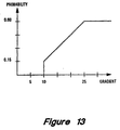
- FIG. 13 is a graph illustrating the application probability of edge sharpening to a color digital halftone image before Ink Relocation as practiced according to one embodiment of the present invention.
- the x axis is the magnitude of the gradient (i.e., the difference in gray value of the neighboring pixel pair), and the y axis is the probability factor that was used in the randomization. The sharpening procedure was applied randomly so that the average application ratio for pixels with a specific probability factor was equal to that factor.
- the above halftone sharpening algorithm uses an image gradient (for sharpening), as does local brightness variation reduction via ink relocation (for possible suppression).
- image gradient for sharpening
- local brightness variation reduction via ink relocation for possible suppression.
- a good gradient estimator i.e., an estimator with some smoothing built in
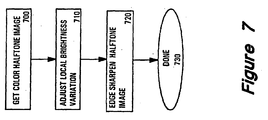
- FIG. 7 is a flow chart illustrating local brightness variation reduction of a color halftone digital image as practiced according to one embodiment of the present invention.
- the color halftone image to process is first retrieved (process 700).
- the entire color halftone image is retrieved at once. Alternately, only a portion of the image is retrieved. It may be the case that only a portion of the image is retrieved because it is only desired to adjust the brightness variation for a portion of the halftone image. However, it may also be the case that multiple portions of the image may be adjusted with different portions of the halftone image being processed either sequentially or in parallel.
- the local brightness variation is adjusted for the halftone image (or portion thereof) retrieved in process 700. If desired, the adjusted halftone image is edge sharpened in process 720 before termination 730.
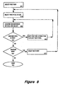
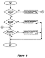
- Figure 8 is a flow chart illustrating control for adjusting local brightness variation (process 710) of a color digital halftone image as practiced according to one embodiment of the present invention.
- the first row of the image to be processed is selected in process 800, and the first pixel in the row is selected in process 810.
- process 820 the neighborhood of the selected pixel is examined and the local minimum brightness variation is adjusted if a candidate pair of adjacent pixels is identified. That is, if the selected pixel and another pixel in the neighborhood of the selected pixel are found to have a non-minimal brightness variation, the values of these two pixels are adjusted so as to minimize the local brightness variation.
- the specific neighboring pixels to be examined can be varied. Typically, examining more neighboring pixels decreases halftone noise, but increases blur, and also increases processing time.
- a test is performed to determine whether there is at least one more pixel in the selected row. If there is another pixel in the row, a shift by one pixel across the row is performed in process 860 to select the next pixel in the row. Processing then continues to process 820 where the neighborhood of the newly-selected pixel is examined and the local minimum brightness variation is again adjusted if a candidate pair of adjacent pixels is identified.
- a test is performed in decision block 840 to determine whether there is at least one more row in the image. If there is another row in the image, a shift by one row in the image is performed in process 870 to form the next selected row. Processing terminates at terminal 850 when all rows have been processed.
- Figure 9 is a flow chart illustrating pixel neighborhood examination and adjustment for the local brightness variation reduction of a color digital halftone image as practiced according to one embodiment of the present invention (process 820).
- the examination and adjustment begins in process 900.
- decision block 910 a test is performed to determine whether the selected pixel has a value of Black. If the selected pixel has a value of Black, then a Black pixel neighborhood adjustment is made in process 950 before proceeding to decision block 930.
- decision block 910 If it was found in decision block 910 that the selected pixel does not have a value of Black, then a test is performed in decision block 920 to determine whether the selected pixel has a value of White. If the selected pixel has a value of White, then a White pixel neighborhood adjustment is made in process 960 before termination at terminal 940.
- decision block 930 determines whether the selected pixel has a value of Blue or Red. If the selected pixel has a value of Blue or Red, then a Blue/Red pixel neighborhood adjustment is made in process 970 before termination at terminal 940.
- skipping decision block 930 and process block 970 will decrease processing time, but will also permit a greater amount of local brightness variation.
- FIG 10 is a flow chart illustrating the black pixel neighborhood local brightness variation reduction portion of a color digital halftone image as practiced according to one embodiment of the present invention (process 950).
- the Black pixel neighborhood examination and adjustment begins in process 1000.
- a test is performed to determine whether the selected pixel has a neighbor pixel with a value of White. If the selected pixel has a White-valued pixel neighbor, then local brightness variation can be reduced by changing the value of the selected pixel from Black to Green and changing the value of the White-valued neighbor to Magenta as shown in process 1015.
- decision block 1010 If it was found in decision block 1010 that the selected pixel does not have a White-valued pixel neighbor, then a test is performed in decision block 1020 to determine whether the selected pixel has a Yellow-valued pixel neighbor. If the selected pixel has a Yellow-valued pixel neighbor, then local brightness variation can be reduced by changing the value of the selected pixel from Black to Red and changing the value of the Yellow-valued neighbor to Green as shown in process 1025.
- decision block 1020 determines whether the selected pixel has a Yellow-valued pixel neighbor. If it was found in decision block 1020 that the selected pixel does not have a Yellow-valued pixel neighbor, then a test is performed in decision block 1030 to determine whether the selected pixel has a Cyan-valued pixel neighbor. If the selected pixel has a Cyan-valued pixel neighbor, then local brightness variation can be reduced by changing the value of the selected pixel from Black to Blue and changing the value of the Cyan-valued neighbor to Green as shown in process 1035.
- decision block 1030 If it was found in decision block 1030 that the selected pixel does not have a Cyan-valued pixel neighbor, then a test is performed in decision block 1040 to determine whether the selected pixel has a Magenta-valued pixel neighbor. If the selected pixel has a Magenta-valued pixel neighbor, then local brightness variation can be reduced by changing the value of the selected pixel from Black to Blue and changing the value of the Magenta-valued neighbor to Red as shown in process 1045.
- a test is performed in decision block 1060 to determine whether the pixel value adjustment is to be suppressed. If it is determined in decision block 1060 that the pixel adjustment is not to be suppressed, then the appropriate pixel value adjustment (i.e., respective process 1015, 1025, 1035 or 1045) is made in process 1070 before termination at terminal 1050.
- FIG 11 is a flow chart illustrating the white pixel neighborhood local brightness variation reduction portion of a color digital halftone image as practiced according to one embodiment of the present invention (process 960).
- the White pixel neighborhood examination and adjustment begins in process 1100.
- a test is performed to determine whether the selected pixel has a neighbor pixel with a value of Black. If the selected pixel has a Black-valued pixel neighbor, then local brightness variation can be reduced by changing the value of the selected pixel from White to Green and changing the value of the Black-valued neighbor to Magenta as shown in process 1115.
- decision block 1110 If it was found in decision block 1110 that the selected pixel does not have a Black-valued pixel neighbor, then a test is performed in decision block 1120 to determine whether the selected pixel has a Blue-valued pixel neighbor. If the selected pixel has a Blue-valued pixel neighbor, then local brightness variation can be reduced by changing the value of the selected pixel from White to Cyan and changing the value of the Blue-valued neighbor to Magenta as shown in process 1125.
- decision block 1120 determines whether the selected pixel has a Blue-valued pixel neighbor. If the selected pixel has a Red-valued pixel neighbor, then local brightness variation can be reduced by changing the value of the selected pixel from White to Yellow and changing the value of the Red-valued neighbor to Magenta as shown in process 1135.
- decision block 1130 If it was found in decision block 1130 that the selected pixel does not have a Red-valued pixel neighbor, then a test is performed in decision block 1140 to determine whether the selected pixel has a Green-valued pixel neighbor. If the selected pixel has a Green-valued pixel neighbor, then local brightness variation can be reduced by changing the value of the selected pixel from White to Yellow and changing the value of the Green-valued neighbor to Cyan as shown in process 1145.
- a test is performed in decision block 1160 to determine whether the pixel value adjustment is to be suppressed. If it is determined in decision block 1160 that the pixel adjustment is not to be suppressed, then the appropriate pixel value adjustment (i.e., respective process 1115, 1125, 1135 or 1145) is made in process 1170 before termination at terminal 1150.
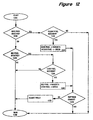
- Figure 12 is a flow chart illustrating the blue/red pixel neighborhood local brightness variation reduction portion of a color digital halftone image as practiced according to one embodiment of the present invention (process 970).
- the Blue/Red pixel neighborhood examination and adjustment begins in process 1200.
- a test is performed to determine whether the selected pixel has a value of Blue. If the selected pixel has a Blue value, then a test is performed in decision block 1220 to determine whether the selected pixel has a neighbor pixel with a value of Yellow. If the Blue-valued selected pixel has a Yellow-valued pixel neighbor, then local brightness variation can be reduced by changing the value of the selected pixel from Blue to Magenta and changing the value of the Yellow-valued neighbor to Green as shown in process 1230.
- decision block 1240 determines whether the selected pixel has a value of Red. If the selected pixel has a Red value, then a test is performed in decision block 1250 to determine whether the selected pixel has a neighbor pixel with a value of Cyan. If the Red-valued selected pixel has a Cyan-valued pixel neighbor, then local brightness variation can be reduced by changing the value of the selected pixel from Red to Magenta and changing the value of the Cyan-valued neighbor to Green as shown in process 1260.
- a test is performed in decision block 1270 to determine whether the pixel value adjustment is to be suppressed. If it is determined in decision block 1270 that the pixel adjustment is not to be suppressed, then the appropriate pixel value adjustment (i.e., respective process 1230 or 1260) is made in process 1280 before termination at terminal 1290.
- the Ink Relocation algorithm can be applied as a post filter to any color halftoned digital image, and it can substantially improve the image quality. It is also reasonably fast to compute.
Landscapes
- Engineering & Computer Science (AREA)
- Multimedia (AREA)
- Signal Processing (AREA)
- Image Processing (AREA)
- Facsimile Image Signal Circuits (AREA)
- Color Image Communication Systems (AREA)
- Particle Formation And Scattering Control In Inkjet Printers (AREA)
- Ink Jet (AREA)
- Record Information Processing For Printing (AREA)
Applications Claiming Priority (2)
| Application Number | Priority Date | Filing Date | Title |
|---|---|---|---|
| US904026 | 1997-07-31 | ||
| US08/904,026 US5991512A (en) | 1997-07-31 | 1997-07-31 | Ink relocation for color halftones |
Publications (3)
| Publication Number | Publication Date |
|---|---|
| EP0895410A2 EP0895410A2 (en) | 1999-02-03 |
| EP0895410A3 EP0895410A3 (en) | 2000-02-02 |
| EP0895410B1 true EP0895410B1 (en) | 2004-06-16 |
Family
ID=25418406
Family Applications (1)
| Application Number | Title | Priority Date | Filing Date |
|---|---|---|---|
| EP98305939A Expired - Lifetime EP0895410B1 (en) | 1997-07-31 | 1998-07-27 | Ink relocation for color halftones |
Country Status (4)
| Country | Link |
|---|---|
| US (1) | US5991512A (https=) |
| EP (1) | EP0895410B1 (https=) |
| JP (1) | JPH11168638A (https=) |
| DE (1) | DE69824496T2 (https=) |
Families Citing this family (19)
| Publication number | Priority date | Publication date | Assignee | Title |
|---|---|---|---|---|
| US6751358B1 (en) * | 1999-06-21 | 2004-06-15 | Xerox Corporation | Error diffusion for digital printing |
| US6870645B1 (en) | 2000-10-03 | 2005-03-22 | Hewlett-Packard Development Company, L.P. | Plane dependent matrix based halftoning |
| US6967753B2 (en) * | 2001-07-31 | 2005-11-22 | Hewlett-Packard Development Company, L.P. | Plane dependent compression |
| US7002708B2 (en) * | 2001-10-29 | 2006-02-21 | Hewlett-Packard Development Company, Lp. | Delayed decision dot placement for plane-dependent CMYK error diffusion |
| US7355747B2 (en) * | 2002-01-18 | 2008-04-08 | Hewlett-Packard Development Company, L.P. | System for improving the speed of data processing |
| JP2005086785A (ja) * | 2003-09-11 | 2005-03-31 | Brother Ind Ltd | 画像処理装置,画像処理方法および画像処理プログラム |
| US7450270B2 (en) * | 2004-01-16 | 2008-11-11 | Hewlett-Packard Development Company, L.P. | Image data processing methods, hard imaging devices, and articles of manufacture |
| KR100611981B1 (ko) * | 2004-05-01 | 2006-08-11 | 삼성전자주식회사 | 이미지의 하프토닝 방법 및 장치 |
| US8614830B2 (en) * | 2004-09-27 | 2013-12-24 | Hewlett-Packard Development Company, L.P. | Pixel exposure as a function of subpixels |
| US7733532B2 (en) | 2004-10-27 | 2010-06-08 | Marvell International Technology Ltd. | Laser print apparatus with dual halftones |
| US8049929B2 (en) * | 2005-09-02 | 2011-11-01 | Xerox Corporation | Color management of halftoned images |
| US7623264B2 (en) | 2006-02-17 | 2009-11-24 | Case Robert M | Method for colorizing a digital halftone |
| US7796836B2 (en) * | 2006-03-03 | 2010-09-14 | General Atomics | Color condensation for image transformation and/or compression |
| JP5012315B2 (ja) * | 2007-08-20 | 2012-08-29 | セイコーエプソン株式会社 | 画像処理装置 |
| US7952764B2 (en) * | 2008-02-05 | 2011-05-31 | Xerox Corporation | Hierarchical color error diffusion in a CMYKRGB domain |
| US7978371B2 (en) * | 2008-02-05 | 2011-07-12 | Xerox Corporation | Vector half-toning with minimum luminance variation dot formation |
| US7916349B2 (en) * | 2008-10-27 | 2011-03-29 | Xerox Corporation | Color pixel error diffusion in a CMYK input color space |
| US9302498B2 (en) * | 2009-05-06 | 2016-04-05 | Xerox Corporation | Microstructured image overcoat layer for improved image uniformity applied with blanket overcoater and functional embossing roller |
| CN110874844A (zh) * | 2018-08-30 | 2020-03-10 | 京东方科技集团股份有限公司 | 线段检测方法、装置和设备 |
Family Cites Families (4)
| Publication number | Priority date | Publication date | Assignee | Title |
|---|---|---|---|---|
| US5070413A (en) * | 1989-10-10 | 1991-12-03 | Eastman Kodak Company | Color digital halftoning with vector error diffusion |
| US5473446A (en) * | 1992-05-04 | 1995-12-05 | Hewlett-Packard Company | Color digital halftoning using black and secondary color replacement and color vector dithering |
| CA2102005C (en) * | 1992-10-30 | 1999-10-12 | Jiro Moriyama | Color ink jet recording method and apparatus using black ink and color-mixed black ink |
| US5768440A (en) * | 1996-12-18 | 1998-06-16 | Xerox Corporation | Adaptive noise removal for video images with less correction of current pixel for higher variations between surrounding pixels |
-
1997
- 1997-07-31 US US08/904,026 patent/US5991512A/en not_active Expired - Fee Related
-
1998
- 1998-07-24 JP JP10209841A patent/JPH11168638A/ja active Pending
- 1998-07-27 DE DE69824496T patent/DE69824496T2/de not_active Expired - Fee Related
- 1998-07-27 EP EP98305939A patent/EP0895410B1/en not_active Expired - Lifetime
Also Published As
| Publication number | Publication date |
|---|---|
| JPH11168638A (ja) | 1999-06-22 |
| DE69824496T2 (de) | 2005-06-23 |
| EP0895410A3 (en) | 2000-02-02 |
| EP0895410A2 (en) | 1999-02-03 |
| US5991512A (en) | 1999-11-23 |
| DE69824496D1 (de) | 2004-07-22 |
Similar Documents
| Publication | Publication Date | Title |
|---|---|---|
| EP0895410B1 (en) | Ink relocation for color halftones | |
| US5621545A (en) | Image production using color error diffusion | |
| EP0895408B1 (en) | Color halftone error-diffusion with local brightness variation reduction | |
| EP0732843B1 (en) | Combined color halftoning | |
| US6580825B2 (en) | Contrast enhancement of an image using luminance and RGB statistical metrics | |
| US6870644B2 (en) | Tone dependent plane dependent error diffusion halftoning | |
| US4984071A (en) | Method of and apparatus for establishing a reference point on a gradation correction curve | |
| US5812744A (en) | Joint design of dither matrices for a set of colorants | |
| EP0720351A2 (en) | Method of and apparatus for producing color proof | |
| US5715073A (en) | Processing by separate stages monochrome digital images to provide halftone color images | |
| US7274817B2 (en) | Conversion of output device color values to minimize image quality artifacts | |
| US7576893B2 (en) | Correlated secondary TRC calibration method | |
| US5581371A (en) | Error diffusion method | |
| US6600573B2 (en) | Fast green/magenta dithering of color images | |
| US6791718B1 (en) | Halftone printing with dither matrices generated by using cluster filters | |
| EP1001609B1 (en) | Processing system and method | |
| Frank et al. | A machine learning approach to design of aperiodic, clustered-dot halftone screens via direct binary search | |
| Shaked et al. | Ink relocation for color halftones | |
| US6847732B1 (en) | Image error diffusion device with noise superposition | |
| Jiang et al. | Color halftoning based on neugebauer primary area coverage | |
| US6891641B1 (en) | Method and apparatus for converting number of colors and processing image data | |
| Lai et al. | Algorithms of halftoning color images with edge enhancement | |
| Liu | Screen-based Watermarking and Color Screen Design Based on Aperiodic Clustered-dot Halftoning | |
| JPH11252388A (ja) | カラー画像処理方法及び装置 | |
| US7277203B1 (en) | Method of improving start-up behavior for color error diffusion digital half-toning |
Legal Events
| Date | Code | Title | Description |
|---|---|---|---|
| PUAI | Public reference made under article 153(3) epc to a published international application that has entered the european phase |
Free format text: ORIGINAL CODE: 0009012 |
|
| AK | Designated contracting states |
Kind code of ref document: A2 Designated state(s): DE FR GB |
|
| AX | Request for extension of the european patent |
Free format text: AL;LT;LV;MK;RO;SI |
|
| PUAL | Search report despatched |
Free format text: ORIGINAL CODE: 0009013 |
|
| AK | Designated contracting states |
Kind code of ref document: A3 Designated state(s): AT BE CH CY DE DK ES FI FR GB GR IE IT LI LU MC NL PT SE |
|
| AX | Request for extension of the european patent |
Free format text: AL;LT;LV;MK;RO;SI |
|
| RIC1 | Information provided on ipc code assigned before grant |
Free format text: 7H 04N 1/52 A, 7H 04N 1/58 B |
|
| 17P | Request for examination filed |
Effective date: 20000320 |
|
| AKX | Designation fees paid |
Free format text: DE FR GB |
|
| RAP1 | Party data changed (applicant data changed or rights of an application transferred) |
Owner name: HEWLETT-PACKARD COMPANY, A DELAWARE CORPORATION |
|
| GRAP | Despatch of communication of intention to grant a patent |
Free format text: ORIGINAL CODE: EPIDOSNIGR1 |
|
| GRAS | Grant fee paid |
Free format text: ORIGINAL CODE: EPIDOSNIGR3 |
|
| GRAA | (expected) grant |
Free format text: ORIGINAL CODE: 0009210 |
|
| AK | Designated contracting states |
Kind code of ref document: B1 Designated state(s): DE FR GB |
|
| REG | Reference to a national code |
Ref country code: GB Ref legal event code: FG4D |
|
| RIN1 | Information on inventor provided before grant (corrected) |
Inventor name: SOBEL, IRWIN Inventor name: FITZHUGH, ANDREW Inventor name: ARAD, NUR Inventor name: SHAKED, DORON |
|
| REF | Corresponds to: |
Ref document number: 69824496 Country of ref document: DE Date of ref document: 20040722 Kind code of ref document: P |
|
| ET | Fr: translation filed | ||
| PLBE | No opposition filed within time limit |
Free format text: ORIGINAL CODE: 0009261 |
|
| STAA | Information on the status of an ep patent application or granted ep patent |
Free format text: STATUS: NO OPPOSITION FILED WITHIN TIME LIMIT |
|
| 26N | No opposition filed |
Effective date: 20050317 |
|
| PGFP | Annual fee paid to national office [announced via postgrant information from national office to epo] |
Ref country code: DE Payment date: 20070831 Year of fee payment: 10 |
|
| PGFP | Annual fee paid to national office [announced via postgrant information from national office to epo] |
Ref country code: GB Payment date: 20070727 Year of fee payment: 10 |
|
| PGFP | Annual fee paid to national office [announced via postgrant information from national office to epo] |
Ref country code: FR Payment date: 20070717 Year of fee payment: 10 |
|
| GBPC | Gb: european patent ceased through non-payment of renewal fee |
Effective date: 20080727 |
|
| PG25 | Lapsed in a contracting state [announced via postgrant information from national office to epo] |
Ref country code: DE Free format text: LAPSE BECAUSE OF NON-PAYMENT OF DUE FEES Effective date: 20090203 |
|
| REG | Reference to a national code |
Ref country code: FR Ref legal event code: ST Effective date: 20090331 |
|
| PG25 | Lapsed in a contracting state [announced via postgrant information from national office to epo] |
Ref country code: GB Free format text: LAPSE BECAUSE OF NON-PAYMENT OF DUE FEES Effective date: 20080727 |
|
| PG25 | Lapsed in a contracting state [announced via postgrant information from national office to epo] |
Ref country code: FR Free format text: LAPSE BECAUSE OF NON-PAYMENT OF DUE FEES Effective date: 20080731 |