EP0895054A2 - Cover for a shaped charge projectile and manufacturing method for such a cover - Google Patents
Cover for a shaped charge projectile and manufacturing method for such a cover Download PDFInfo
- Publication number
- EP0895054A2 EP0895054A2 EP98114479A EP98114479A EP0895054A2 EP 0895054 A2 EP0895054 A2 EP 0895054A2 EP 98114479 A EP98114479 A EP 98114479A EP 98114479 A EP98114479 A EP 98114479A EP 0895054 A2 EP0895054 A2 EP 0895054A2
- Authority
- EP
- European Patent Office
- Prior art keywords
- cover member
- warhead
- solid cover
- solid
- cover
- Prior art date
- Legal status (The legal status is an assumption and is not a legal conclusion. Google has not performed a legal analysis and makes no representation as to the accuracy of the status listed.)
- Granted
Links
Images


Classifications
-
- F—MECHANICAL ENGINEERING; LIGHTING; HEATING; WEAPONS; BLASTING
- F42—AMMUNITION; BLASTING
- F42B—EXPLOSIVE CHARGES, e.g. FOR BLASTING, FIREWORKS, AMMUNITION
- F42B12/00—Projectiles, missiles or mines characterised by the warhead, the intended effect, or the material
- F42B12/02—Projectiles, missiles or mines characterised by the warhead, the intended effect, or the material characterised by the warhead or the intended effect
- F42B12/04—Projectiles, missiles or mines characterised by the warhead, the intended effect, or the material characterised by the warhead or the intended effect of armour-piercing type
- F42B12/10—Projectiles, missiles or mines characterised by the warhead, the intended effect, or the material characterised by the warhead or the intended effect of armour-piercing type with shaped or hollow charge
- F42B12/14—Projectiles, missiles or mines characterised by the warhead, the intended effect, or the material characterised by the warhead or the intended effect of armour-piercing type with shaped or hollow charge the symmetry axis of the hollow charge forming an angle with the longitudinal axis of the projectile
Definitions
- the present invention is generally related to a warhead delivery system, and more specifically to explosively-formed penetrator (EFP) warheads, and more particularly to a cover for an aerostable explosively-formed penetrator warhead.
- EFP explosively-formed penetrator
- Warhead delivery systems In military ordnance arts, destructive devices known as warhead delivery systems, and commonly referred to as simply “Warheads,” have been developed to accomplish a wide variety of military mission requirements.
- a warhead generally refers to a combination of components including, among others, a projectile designed to destroy a target upon impact, an explosive material or charge, a firing means or explosive mechanism intended to detonate the explosive charge and thereby forcibly propel or launch the projectile toward a target, a warhead housing by which the projectile and explosive charge are self contained before firing, and a launch tube for generally holding the warhead housing or canister.
- a delivery vehicle commonly carries the warhead to an area near or over the target.
- the projectiles of the warhead may be of several types including, among others, explosive projectiles containing an explosive charge that detonates upon impact with a target, and explosively formed penetrator (EFP) warheads having warhead kill mechanisms in the form of, for example, multiple fragments, a stretched rod EFP, and an aerostable EFP.
- a multiple fragment EFP warhead consists of multiple and relatively small individual projectiles fired concurrently from a warhead, and is particularly suited for destruction in shotgun-like fashion of multiple targets in proximity to each other, such as enemy missiles housed on a launch platform.
- a stretched rod EFP and an aerostable EFP type of warhead are particularly suited for destruction of single targets that have substantial defensive capability, e.g., enemy tanks with heavy armor plating. This is so since a stretched rod or aerostable EFP is a singular projectile warhead capable of piercing through such plating.
- An aerostable EFP is a projectile that is explosively formed from a generally preformed disk-shaped member, commonly referred to as the liner.
- the liner is adapted to conform to the lateral cross section of a housing or canister, and also serves as an end cap for the explosive charge within the housing.
- the liner is advantageously deformed by a shock wave or expanding combustion gas impact of the detonated explosive charge within the housing, and, in turn, the liner becomes relatively axially elongated as it exits the housing.
- the elongation becomes conical in appearance as particularly illustrated in Figure 9. That is, the resulting aerostable EFP projectile progressively has a widening diameter from its forward or nose end to its rearward or tail end.
- Such post-firing conical shaping is advantageous because the aerostable EFP projectile becomes relatively aerodynamically stable, as its name implies, and is constructed to have flight characteristics similar to that of a rifle bullet.
- EFP warhead delivery systems are generally secured in place in a launch tube of a the warhead delivery vehicle such that the exit end of the warhead housing and launch tube, i.e., the end where the EFP projectile exits, is generally very proximate to a projectile exit aperture in the outer skin surface of the warhead delivery vehicle.
- warhead delivery systems are generally required to survive in hostile environments, and be capable of performing their destructive mission roles completely and with a high degree of accuracy.
- warheads carried aboard delivery vehicles such as cruise missiles and the like, are designed to be sheltered or protected from detection and destruction by enemy defense systems.
- EFP warhead integrates into the warhead delivery vehicle often requires that the warhead shoot through an aerodynamic warhead covering device.
- the covering device is commonly configured to fill the projectile exit aperture and have an outer surface that conforms to the outer skin surface of the delivery vehicle. This is so that the aerodynamic stability of the warhead delivery vehicle is maintained, and secondarily diminishes detection by the enemy defense systems.
- These EFP warhead covering devices are commonly referred to as shoot-through aerodynamic covers. They have often been constructed of a rigid material, such as a frangible plastic material or the like, that has an adverse affect on the EFP projectile formation as the liner impacts the cover as will be described in further detail below.
- a selected EFP warhead projectile for example, a single stretched rod EFP or aerostable EFP
- the shoot-through cover is designed to readily break apart upon impact by the projectile as the projectile exits the housing.
- the shoot-through cover often degrades the intended EFP projectile's shape formation and performance as compared to the shape formation without shooting through the shoot-through cover. This is thought to be caused by random fracturing of the EFP "first formed” or “forming” projectile as it impacts the cover and passes therethrough. This is due, in part, to a loss of momentum experienced by the projectile immediately after firing when it contacts the cover, and to aerodynamic instability as the impact of the projectile with the cover displaces the resulting projectile from its intended flight path.
- the impact of the first formed or "forming" projectile onto the cover commonly causes the resulting or exiting EFP projectile to exhibit aerodynamic stability degradation, and may also degrade the intended flight path.
- the resulting projectile is designed to develop fins at its rearward end due to liner deformation through combustion gas impact, after becoming conically elongated, as aforementioned.
- the fins function much like fixed stabilizing control surfaces on the delivery vehicle to provide aerodynamic stability.
- shoot-through covers of the prior art detrimentally disrupt the fin formation because of the impact of the first formed projectile with the cover. This is illustrated in Figure 9 by the rough or jagged peripheral end of the aft section of the projectile.
- warhead covers are first destroyed by a pyrotechnic device just before the warhead is detonated, and the EFP projectile passes through the projectile exit aperture.
- pre-removal covering devices generally add significant complexity and cost to the warhead vehicle delivery system.
- an improved shoot-through warhead cover is constructed of a low density material, such as polyethylene foam, in a dome-like shape having mass symmetry.
- An anterior surface of the shoot-through cover is configured so as to be in a proximate mating relationship with the exterior surface of the EFP liner member.
- the exterior surface of the cover is also aerodynamically contoured to match the external shape of a receiving delivery vehicle body.
- the cover may advantageously be constructed so as to exhibit a non-uniform mass profile while maintaining mass symmetry, where the cover includes a plurality of radial portions having a higher mass density than other portions thereof, and wherein the plurality of radial portions are substantially equally angularly displaced about a central cover axis so as to enhance formation of fins onto the emerging EFP projectile passing through the cover.
- Yet another object of the invention is to provide an EFP projectile having mass-symmetry.
- FIG 1 is a representation of a plan view of a warhead delivery vehicle 200 incorporating a shoot-through cover 50 in accordance with the present invention.
- warhead delivery vehicle 200 is constructed to carry a warhead 100 ( Figure 2) secured in place, by conventional means (not shown).
- Delivery vehicle 200 may be, for example, a cruise missile.
- Another example of a delivery vehicle 200 is one referred to as a Low Cost Anti-Armor Submunition (LOCAAS) developed by Loral Vought Systems.
- LOCAAS delivery vehicle 200 provides seeker/sensor and airframe technology to autonomously detect, acquire, and classify targets according to target type.
- Warhead delivery vehicle 200 includes an outer body surface 210 having a combination warhead housing receiving aperture and projectile exit aperture generally depicted by numeral 220.
- FIGS. 2 and 3 thereshown are partial cross-sectional views of warhead 100 secured in place to warhead delivery vehicle 200 along detail section lines 2-2 and 3-3, respectively.
- a generally cylindrical canister or launch tube 205 having an inward end 207 and an exit port 209 centrally aligned with projectile exit aperture 220 of outer skin surface 220 of vehicle 200.
- Launch tube 205 is geometrically configured to receive a pre-launch aerostable EFP warhead generally indicated by numeral 100 similar to those manufactured by Alliant Techsystems, Hopkins, Minnesota, in accordance with "Anti-Material Submunition Warhead Technology (AWST)" as described in a product brochure identified as 16247 8/95.
- AST Anti-Material Submunition Warhead Technology
- EFP warhead 100 generally includes a cylindrically shaped housing 20, explosive charge 30, and pre-formed disk shaped member 40 commonly referred to as a liner.
- Housing 20 serves as an EFP projectile forming chamber for producing an explosively formed aerostable EFP projectile that is intended to be solely constructed from liner 40 in a manner as is well known in the art.
- Liner 40 is illustrated in Figure 2 as having inner and outer opposed surfaces 42 and 44, respectively.
- Liner 40 is suitably constructed to be press fit into place through an open end 22 of housing 20.
- Liner 40 serves as an "explosive end cap” by which explosive charge 30 is held in place and sealed within housing 20 by inner surface 42 of liner 40 and the peripheral surfaces thereof.
- liner 40 is generally conically shaped having the convex side thereof, namely surface 42, in direct proximity to explosive charge 30.
- Liner 40 is typically constructed of soft metallic material, such as a copper based material
- housing 20 is generally constructed of a high-strength light weight material such as aluminum, as is commonly known in the art.
- Explosive charge 30 is constructed to be detonated by a suitable conventional firing or detonating mechanism (not shown). Explosive charge 30 may advantageously be selected so as to be sufficient to both form the EFP projectile as well as propel the projectile with sufficient velocity so as to serve as the kill mechanism.
- One example of explosive charge 30 commonly employed in EFP warheads is a well known high-energy and reduced sensitivity plastic bonded explosive PBXN-9.
- a generally circular and solid "dome-shaped" shoot-through cover 50 including a generally convex surface 52, and a second generally convex surface 54, opposite the convex surface 52.
- Convex surface 52 of cover 50 is configured so as to be in proximate mating relationship with the exterior surface 44 of liner 40.
- the proximate mating relationship is such that convex surface 52 of cover 50 is in intimate contact with exterior surface 44 of liner 40.
- a cover 50 is inserted in projectile exit aperture 220 and includes an outer surface 54 configured to minimize aerodynamic disruption of fluid flow along outer body surface 210, when the vehicle 200 is in flight. More specifically, the outer surface 54 is formed to substantially match the cylindrical contour of outer skin surface 210 of vehicle 200 so as to minimize any discontinuities in the outer surface 210 of vehicle body 200 when the cover 50 is in place within projectile exit aperture 220.
- warhead delivery vehicle 200 is deployed from a weapon dispenser (not pictured) and flies to a target area. After flying to the target area, the warhead delivery vehicle 200 will search, detect, and attack, through warhead 100 deployment, a selected target. Deployment of the warhead 100 is built by the following steps. First, the explosive 30 is detonated by a firing mechanism (not shown). Second, the detonation of the explosive charge 30 causes deformation of liner 40, as aforedescribed, and propels outward from housing 20.
- Liner 40 Propulsion forward of liner 40 caused by the combustion gases of explosive charge 30 results in liner 40 becoming a somewhat slender and conically shaped projectile as has been described above for forming the well known EFP projectile as is depicted in Figure 8, and more specifically the aerostable EFP warhead projectile. During this deformation and conical shaping of liner 40, liner 40 continues to be propelled toward and through cover 50.
- cover 50 is constructed of a low density material in which surface 52 is in intimate contact with the free surface of the liner, namely outer surface 44 of liner 40, and the outer surface 54 is contoured to conform with the aerodynamic outer skin surface 210 of warhead delivery vehicle 200.
- the cover is constructed of a polymer foam, for example, polyethylene foam. Other types of equivalent low density material may be substituted.
- cover 50 is constructed to have a selected mass and mass symmetry while being dimensionally asymmetric.
- Figures 4, 5, and 6a - 6c illustrate components employed in the construction of a shoot-through cover in accordance with the present invention.
- one method of constructing a cover 50 in accordance with the present invention starts with a base 400 of polyethylene foam in the form of an 8 inch diameter right circular cylinder. Base 400 is then heated and compressed into a mold by using an arbor press to form cover 50 with mass symmetry in accordance with the present invention as is particularly illustrated in Figures 2 and 3.
- cover 50 is constructed to have a non-uniform mass profile about the central axis 420 of cover 50 where there exist radial portions of cover 50 that have a higher density than other portions thereof, and that are substantially equally angularly displaced about the central axis 420 thereof.
- the increased mass radial portions are symmetrically located about the central axis 420 of cover 50 as will be further explained.
- a cover having these characteristics as just described may be made by employment of additional polymer foam wedges or pieces that are first affixed to the base 400 before being heated and compressed to obtain the desired geometric configuration.
- FIG. 6 a-c An example of a method for making a cover 50 having a mass density profile as just described begins with providing a base 400 as illustrated in Figure 4, and affixing thereto substantially equally angularly placed foam wedges 600 radially positioned about central axis 420 as particularly illustrated in Figure 5.
- Wedges 600 are more particularly illustrated in Figures 6 a-c illustrating a top plan view, lateral side view, and end view respectively.
- Wedge 600 includes trapezoidal sides 610, inwardly leaning triangular end 620, rectangular base 630, and triangular end 640 (view not shown) perpendicular to base 630.
- the wedges 600 are aligned on base 400 such that the wedge edge 650 of each wedge 600 is aligned with line segments extending radially away from central axis 420, and that the triangular end 640 is close to the circumferential perimeter edge 415 of base 400.
- These wedges 600 may be held in place by a known adhesive.
- the assembly illustrated in Figure 5 is then heated and compressed into a mold by way of an arbor press to form cover 50.
- the resulting compressed foam cover 50 resulting from the assembly as illustrated in Figure 5 will have geometrical characteristics as already described with reference to Figures 2 and 3, but which will also have mass symmetry with a non-uniform mass profile about the central axis in a manner such that there exists higher mass radial portions of cover 50 that have a higher density than other portions thereof, and that are substantially equally angularly displaced about the central axis 420 thereof. While the example of Figure 5 shows an embodiment having six wedges 600, the invention is not so limited. Useful embodiments may be constructed with as few as three such wedges or more than six.
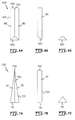
- a cover 50 having a mass profile as just described beneficially affects the formation of a resultant EFP projectile so as to result in making substantially smooth uniform fin formations similar to those depicted in the sketch of an EFP projectile 800 as illustrated in Figure 8.
- the resulting peripheral edges 820 of the aft section tend to be smooth, thereby providing a greater degree of aerodynamic stability. This may be readily contrasted with the rougher edges 920 as produce by projectiles 900 of the prior art as illustrated in Figure 9.
- fin formations 810 are thought to be caused by the effect of the mass profile and mass symmetry of the cover as the initially formed EFP projectile passes through the low density cover.
- cover 50 having six substantially equally angularly positioned radial mass portions as obtained by constructing the cover with six wedges as aforedescribed, experimentation has exhibited a projectile similar to that of Figure 8 with several distinct fin formations 810.
- the number of wedges may be increased or decreased, and may more or less result in a similar number of projectile fin formations in proportion to the number of substantially equally angularly radial mass portions as the projectile passes through the cover.
- Wedge 700 includes a triangular end 710 perpendicular to a triangular base 720, and sides 715 and 717. One end of each of sides 715 and 717 forms a singular edge 740.
- a plurality of wedges 700 may be substantially equally angularly and radially aligned on a base 400 such that triangular end 710 is closest to the circumferential perimeter edge 415 of base 400.
- a cover 50 constructed in a manner as already described, i.e., by heating and compressing, with one of a base 400 and either of wedge types 600 or 700, will exhibit a mass profile where the mass distribution is such that there exists higher mass density portions located radially away from the central axis 420 of base 400.
- the higher mass density portions are substantially equally angularly located about central axis 420. It is thought that this arrangement tends to enhance the formation of substantially equally angularly placed depressions in the resulting formation of the EFP projectile so as to produce a plurality of substantially equally angularly fin like formations in the resultant EFP projectile after exiting the shoot-through cover 50 in accordance with the present invention.
- a cover 50 was constructed using six (6) wedges 600 constructed similar to one shown in Figure 6.
- Each wedge had a rectangular base 630 with dimensions of 0.77 by 2.38 inches, a triangular end perpendicular to the base with height of .39 inches, and a second inward leading triangular end 620 with the top edge 650 measuring 2.03 inches.
- the wedges were then symmetrically affixed in place by an adhesive on base 400 as illustrated in Figure 5.
- the cover pre-form assembly was placed in a mold and heated. Afterwards, the mold was placed in an arbor press to compress the material and form the desired cover configuration as illustrated in Figures 2 and 3.
- cover 50 has been constructed of a low density material that is compressed in a mold to obtain the desired final form.
- a polymer foam such as polyethylene has been suggested as the starting material, but other known materials may be employed to achieve the improved EFP projectile characteristics of the invention, without the degradation of the projectile as heretofore observed with covers of the prior art.
- the mass density of a cover may be altered so as to have a predetermined mass profile symmetrically about the central axis of the cover to enhance fin development of the EFP projectile.
- cover 50 there is a wide choice of low density materials that may be employed in the formation of cover 50 in accordance with the present invention. Further, a wide array of molding techniques may be utilized in order to make a warhead cover as particularly described and claimed herein. As will be appreciated by those skilled in the art having the benefit of this disclosure, the invention is not limited to those wedge configurations illustrated in Figures 6a-c and Figures 7 a-c. Further still, the invention is not limited to a shoot-through cover that will enhance fin formation, but may be employed for projectiles of other aerodynamically stable shapes. Other equivalent configurations of various geometric shapes may be used to promote good fin formation.
Landscapes
- Engineering & Computer Science (AREA)
- Chemical & Material Sciences (AREA)
- Combustion & Propulsion (AREA)
- General Engineering & Computer Science (AREA)
- Aiming, Guidance, Guns With A Light Source, Armor, Camouflage, And Targets (AREA)
- Radar Systems Or Details Thereof (AREA)
Abstract
Description
Claims (24)
- A warhead delivery system, wherein a penetrator warhead is an explosively shaped projectile formed from a liner member, the warhead delivery system comprising:a penetrator warhead including,a housing for containing an explosive charge,a liner member constructed to be formed into a projectile subsequent to detonation of said explosive charge and to exit said housing substantially along a reference launch axis, said liner member having an anterior surface in proximity to said explosive charge, and an opposite exterior surface;a vehicle body for carrying said penetrator warhead, said vehicle body including,means for securing said penetrator warhead within said vehicle body,an exterior skin surface having a known contour, anda projectile exit aperture through said exterior skin surface through which said projectile is adapted to be launched therethrough; anda solid cover member constructed of a low density material in a manner so as to have substantial mass symmetry relative to a central axis passing therethrough, and configured for mating relationship with said vehicle body aperture and said exterior surface of said liner member, said cover member having a shape and dimensional construction such that, with said cover member being inserted into said vehicle body aperture, an exterior cover member surface has substantially the same characteristics as said known contour of said vehicle body exterior skin surface, and an anterior cover member surface, substantially opposite said exterior surface, is in proximate mating relationship with said exterior surface of said liner member.
- The warhead delivery system of claim 1 wherein said low density material comprises polyethylene foam.
- The warhead delivery system of claim 1 wherein said anterior surface of said solid cover member is in intimate contact with said exterior surface of said liner member.
- The warhead delivery system of claim 1 wherein said solid cover member is constructed to have a non-uniform mass profile about a reference cover central axis passing through said exterior surface and said anterior surface of said solid cover member and generally aligned with said reference launch axis, such that there exists a plurality of radial portions of said solid cover member having a higher mass density than other portions thereof, wherein the plurality of radial portions are substantially equally angularly displaced about said reference cover central axis so as to enhance formation of fins onto said explosively shaped projectile passing through said solid cover member.
- The warhead delivery system of claim 4 wherein said low density material comprises polyethylene foam.
- The warhead delivery system of claim 4 wherein said anterior surface of said solid cover member is in intimate contact with said exterior surface of said liner member.
- The warhead delivery system of claim 1 wherein said solid cover member is constructed to have a non-uniform mass profile about a reference cover central axis passing through said exterior surface and said anterior surface of said solid cover member wherein the reference cover central axis is generally aligned with said reference launch axis, such that there exists at least three radial portions of said solid cover member having a higher mass density than other portions thereof, wherein the at least three radial portions are substantially equally angularly displaced about said reference cover central axis so as to enhance formation of fins onto said explosively shaped projectile passing through said solid cover member.
- The warhead delivery system of claim 7 wherein said low density material comprises polyethylene foam.
- The warhead delivery system of claim 7 wherein said anterior surface of said solid cover member is in intimate contact with said exterior surface of said liner member.
- A cover for a warhead delivery system, wherein a penetrator warhead is an explosively formed penetrator warhead in which a projectile is explosively formed from a liner member initially contained within a housing having an explosive charge therein, wherein the liner member has a liner member exterior surface, and wherein said liner member is adapted to be formed into a projectile subsequent to detonation of said explosive charge for passing through an aperture through an exterior skin surface of a vehicle body carrying said explosively formed penetrator warhead, said cover comprising:a solid cover member constructed of a low density material so as to have substantial mass symmetry relative to a central axis passing therethrough, and configured for a mating relationship with said vehicle body aperture and said liner member exterior surface, said solid cover member having a shape and dimensional construction such that, with said solid cover member being inserted into said vehicle body aperture, a solid cover member exterior surface has substantially the same characteristics as said known contour of said vehicle body exterior skin surface, and a solid cover member anterior surface, substantially opposite said solid cover member exterior surface, is in proximate mating relationship with said liner member exterior surface.
- The cover of claim 10 wherein said low density material comprises polyethylene foam.
- The cover of claim 10 wherein said solid cover member anterior surface is configured so as to be in intimate contact with said liner member exterior surface.
- The cover of claim 10 wherein said solid cover member comprises a non-uniform mass profile about a reference cover central axis passing through said solid cover member exterior surface and said solid cover member anterior surface, such that there exists a plurality of radial portions of said solid cover member having a higher mass density than other portions thereof, wherein the plurality of radial portions are substantially equally angularly displaced about said reference cover central axis so as to enhance formation of fins onto said projectile passing through said solid cover member.
- The cover of claim 13 wherein said low density material comprises polyethylene foam.
- The cover of claim 13 wherein said solid cover member anterior surface is in intimate contact with said exterior surface of said liner member.
- The cover of claim 10 wherein said solid cover member is constructed to have a non-uniform mass profile about a reference cover central axis passing through said solid cover member exterior surface and said solid cover member anterior surface such that there exists at least three radial portions of said solid cover member having a higher mass density than other portions thereof, wherein the at least three radial portions are substantially equally angularly displaced about said reference cover central axis so as to enhance formation of fins onto a projectile passing through said solid cover member.
- The cover of claim 16 wherein said low density material comprises polyethylene foam.
- The cover of claim 16 wherein said solid cover member anterior surface is in intimate contact with said liner member exterior surface.
- A method for constructing a shoot-through warhead cover for a warhead delivery system wherein the warhead is an explosively formed penetrator warhead in which a projectile is explosively formed from a liner member initially contained within a housing having an explosive charge therein, and wherein the liner member is constructed to be formed into a projectile subsequent to detonation of said explosive charge and pass through an aperture through an exterior skin surface of a vehicle body carrying said explosively formed penetrator warhead, said method comprising the steps of:heating a right circular cylinder of a low density;compressing said cylinder in a mold so as to produce a solid cover member having substantial mass symmetry relative to a longitudinal central axis passing therethrough; andfurther configuring said solid cover member in said mold for mating relationship with said vehicle body aperture and said exterior surface of said liner member, so that said solid cover member has a shape and dimensional construction such that, with said solid cover member being inserted into said vehicle body aperture, said solid cover member includes a solid member exterior surface that has substantially the same characteristics as the contour of said vehicle body exterior skin surface, and wherein said solid cover member also includes an anterior surface, substantially opposite said exterior surface, in proximate mating relationship with said solid member exterior surface of said liner member.
- The method of claim 19 wherein said low density material is comprised substantially of a polyethylene foam material.
- The method of claim 19 wherein said mold is configured to produce said solid cover member such that said anterior surface of said solid cover member is in intimate contact with said exterior surface of said liner member.
- The method of claim 19 further comprising steps of:adhering a plurality of wedge members to said cylinder, wherein the plurality of wedge members are radially aligned relative to said longitudinal central axis and substantially equally angularly spaced apart;heating the combination of said cylinder and said wedge members; andcompressing said combination in said mold so as to produce said solid cover member having both mass symmetry and a non-uniform mass profile about a reference cover central axis passing through said exterior surface and said anterior surface of said solid cover such that there exists a plurality of radial portions of said solid cover member having a higher mass density than other portions thereof, wherein the plurality of radial portions are substantially equally angularly displaced about said reference cover central axis so as to enhance formation of fins onto said projectile passing through said solid cover member.
- The method of claim 22 wherein said low density material comprises polyethylene foam.
- The method of claim 22 wherein said mold is configured to produce said solid cover member such that said anterior surface of said solid cover member is in intimate contact with said exterior surface of said liner member.
Applications Claiming Priority (2)
| Application Number | Priority Date | Filing Date | Title |
|---|---|---|---|
| US905174 | 1997-08-01 | ||
| US08/905,174 US5925845A (en) | 1997-08-01 | 1997-08-01 | Shoot-through cover for an explosively formed penetrator warhead |
Publications (3)
| Publication Number | Publication Date |
|---|---|
| EP0895054A2 true EP0895054A2 (en) | 1999-02-03 |
| EP0895054A3 EP0895054A3 (en) | 2000-07-12 |
| EP0895054B1 EP0895054B1 (en) | 2005-09-21 |
Family
ID=25420388
Family Applications (1)
| Application Number | Title | Priority Date | Filing Date |
|---|---|---|---|
| EP98114479A Expired - Lifetime EP0895054B1 (en) | 1997-08-01 | 1998-07-31 | Cover for a shaped charge projectile |
Country Status (4)
| Country | Link |
|---|---|
| US (1) | US5925845A (en) |
| EP (1) | EP0895054B1 (en) |
| DE (1) | DE69831634T2 (en) |
| IL (1) | IL125538A (en) |
Families Citing this family (5)
| Publication number | Priority date | Publication date | Assignee | Title |
|---|---|---|---|---|
| GB2503186B (en) * | 2009-11-25 | 2015-03-25 | Secr Defence | Shaped charge casing |
| US8616130B2 (en) | 2011-01-19 | 2013-12-31 | Raytheon Company | Liners for warheads and warheads having improved liners |
| US11614311B1 (en) | 2016-03-22 | 2023-03-28 | Northrop Grumman Systems Corporation | Prefragmented warheads with enhanced performance |
| US10634472B1 (en) | 2016-03-22 | 2020-04-28 | Northrop Grumman Innovation Systems, Inc. | Prefragmented warheads with enhanced performance |
| CN109163621B (en) * | 2018-09-17 | 2022-04-01 | 中北大学 | Can realize that EFP rotational stabilization flies gather can charge structure |
Family Cites Families (12)
| Publication number | Priority date | Publication date | Assignee | Title |
|---|---|---|---|---|
| GB2176878B (en) * | 1979-08-14 | 1987-09-03 | Royal Ordnance Plc | Hollow charges |
| DE3329969C1 (en) * | 1983-08-19 | 1990-06-13 | Fraunhofer Ges Forschung | Device for producing explosive-formed projectiles |
| DE3433140A1 (en) * | 1984-09-08 | 1986-03-20 | Diehl GmbH & Co, 8500 Nürnberg | AMMUNITION, IN PARTICULAR MORE AMMUNITION |
| FR2632394B1 (en) * | 1986-07-24 | 1990-11-30 | France Etat Armement | EXPLOSIVE LOAD GENERATOR OF CORE |
| GB2214618B (en) * | 1988-01-28 | 1990-04-18 | Royal Ordnance Plc | Explosive devices and methods of use thereof |
| DE3906098A1 (en) * | 1988-02-29 | 1989-09-07 | Deutsch Franz Forsch Inst | Shaped-charge projectile for attacking while overflying |
| DE3830527A1 (en) * | 1988-09-08 | 1990-03-22 | Diehl Gmbh & Co | PROJECT-FORMING INSERT FOR HOLLOW LOADS AND METHOD FOR PRODUCING THE INSERT |
| US5365852A (en) * | 1989-01-09 | 1994-11-22 | Aerojet-General Corporation | Method and apparatus for providing an explosively formed penetrator having fins |
| DE3920017A1 (en) * | 1989-06-20 | 1991-01-10 | Messerschmitt Boelkow Blohm | War-head penetrating ships hull - has external fins maintaining the war-head posture before penetration |
| DE3933955A1 (en) * | 1989-10-11 | 1991-04-18 | Diehl Gmbh & Co | Shock resistant fixing of retaining ring of ammunition shell - reactive polymer is foamed in-situ to penetrate holes in retaining ring and gap between shell and ring |
| DE4029876A1 (en) * | 1990-09-21 | 1992-03-26 | Diehl Gmbh & Co | AMMUNITION WITH A FOAM SUPPORT BODY |
| FR2706600B1 (en) * | 1991-06-21 | 1995-10-13 | Thomson Brandt Armements | Core-generating charge comprising means for correcting the effects of a drive rotation. |
-
1997
- 1997-08-01 US US08/905,174 patent/US5925845A/en not_active Expired - Lifetime
-
1998
- 1998-07-28 IL IL12553898A patent/IL125538A/en unknown
- 1998-07-31 DE DE69831634T patent/DE69831634T2/en not_active Expired - Fee Related
- 1998-07-31 EP EP98114479A patent/EP0895054B1/en not_active Expired - Lifetime
Non-Patent Citations (1)
| Title |
|---|
| "anti-material submunition warhead technology (awst), as described in a product brochure identified as 16247 8/95", ALLIANT TECHSYSTEMS, HOPKINS, MINNESOTA |
Also Published As
| Publication number | Publication date |
|---|---|
| EP0895054A3 (en) | 2000-07-12 |
| IL125538A0 (en) | 1999-03-12 |
| IL125538A (en) | 2001-01-28 |
| DE69831634D1 (en) | 2006-02-02 |
| DE69831634T2 (en) | 2006-06-14 |
| US5925845A (en) | 1999-07-20 |
| EP0895054B1 (en) | 2005-09-21 |
Similar Documents
| Publication | Publication Date | Title |
|---|---|---|
| US6186070B1 (en) | Combined effects warheads | |
| RU2275585C2 (en) | Method for control of missile flight direction and missile | |
| EP0813674B1 (en) | Dual operating mode warhead and method of operating such a warhead | |
| US5191169A (en) | Multiple EFP cluster module warhead | |
| US3877383A (en) | Munition | |
| US20080307994A1 (en) | Warhead | |
| JP2008512642A (en) | Kinetic energy rod warhead with narrow open angle | |
| US4854240A (en) | Two-stage shaped charge projectile | |
| US5648637A (en) | Multi-disk shell | |
| US6510797B1 (en) | Segmented kinetic energy explosively formed penetrator assembly | |
| KR100796706B1 (en) | Artillery projectile comprising an interchangeable payload | |
| US4459915A (en) | Combined rocket motor warhead | |
| US6308634B1 (en) | Precursor-follow through explosively formed penetrator assembly | |
| US4498394A (en) | Arrangement for a terminally guided projectile provided with a target seeking arrangement and path correction arrangement | |
| US20200300591A1 (en) | Warheads and weapons and methods including same | |
| US6988450B1 (en) | Anti-personnel ammunition | |
| US6161482A (en) | Multi-disk shell and wad | |
| JP2003520937A (en) | Missile intercept missile | |
| US4337911A (en) | Non-spinning projectile | |
| US5925845A (en) | Shoot-through cover for an explosively formed penetrator warhead | |
| RU2118788C1 (en) | Above-caliber grenade | |
| US20090288573A1 (en) | Warhead for intercepting system | |
| US5363766A (en) | Remjet powered, armor piercing, high explosive projectile | |
| RU2127861C1 (en) | Ammunition for hitting of shells near protected object | |
| EP0084095A2 (en) | Ballistic propulsion system for rifle grenades and similar projectiles |
Legal Events
| Date | Code | Title | Description |
|---|---|---|---|
| PUAI | Public reference made under article 153(3) epc to a published international application that has entered the european phase |
Free format text: ORIGINAL CODE: 0009012 |
|
| AK | Designated contracting states |
Kind code of ref document: A2 Designated state(s): DE FR GB |
|
| AX | Request for extension of the european patent |
Free format text: AL;LT;LV;MK;RO;SI |
|
| PUAL | Search report despatched |
Free format text: ORIGINAL CODE: 0009013 |
|
| AK | Designated contracting states |
Kind code of ref document: A3 Designated state(s): AT BE CH CY DE DK ES FI FR GB GR IE IT LI LU MC NL PT SE |
|
| AX | Request for extension of the european patent |
Free format text: AL;LT;LV;MK;RO;SI |
|
| RIC1 | Information provided on ipc code assigned before grant |
Free format text: 7F 42B 12/10 A, 7F 42B 12/14 B |
|
| 17P | Request for examination filed |
Effective date: 20001114 |
|
| AKX | Designation fees paid |
Free format text: DE FR GB |
|
| 17Q | First examination report despatched |
Effective date: 20040216 |
|
| GRAP | Despatch of communication of intention to grant a patent |
Free format text: ORIGINAL CODE: EPIDOSNIGR1 |
|
| RTI1 | Title (correction) |
Free format text: COVER FOR A SHAPED CHARGE PROJECTILE |
|
| GRAS | Grant fee paid |
Free format text: ORIGINAL CODE: EPIDOSNIGR3 |
|
| GRAA | (expected) grant |
Free format text: ORIGINAL CODE: 0009210 |
|
| AK | Designated contracting states |
Kind code of ref document: B1 Designated state(s): DE FR GB |
|
| REG | Reference to a national code |
Ref country code: GB Ref legal event code: FG4D |
|
| REF | Corresponds to: |
Ref document number: 69831634 Country of ref document: DE Date of ref document: 20051027 Kind code of ref document: P |
|
| REF | Corresponds to: |
Ref document number: 69831634 Country of ref document: DE Date of ref document: 20060202 Kind code of ref document: P |
|
| ET | Fr: translation filed | ||
| PLBE | No opposition filed within time limit |
Free format text: ORIGINAL CODE: 0009261 |
|
| STAA | Information on the status of an ep patent application or granted ep patent |
Free format text: STATUS: NO OPPOSITION FILED WITHIN TIME LIMIT |
|
| 26N | No opposition filed |
Effective date: 20060622 |
|
| PGFP | Annual fee paid to national office [announced via postgrant information from national office to epo] |
Ref country code: FR Payment date: 20090717 Year of fee payment: 12 |
|
| PGFP | Annual fee paid to national office [announced via postgrant information from national office to epo] |
Ref country code: GB Payment date: 20090727 Year of fee payment: 12 Ref country code: DE Payment date: 20090729 Year of fee payment: 12 |
|
| GBPC | Gb: european patent ceased through non-payment of renewal fee |
Effective date: 20100731 |
|
| REG | Reference to a national code |
Ref country code: FR Ref legal event code: ST Effective date: 20110331 |
|
| PG25 | Lapsed in a contracting state [announced via postgrant information from national office to epo] |
Ref country code: DE Free format text: LAPSE BECAUSE OF NON-PAYMENT OF DUE FEES Effective date: 20110201 |
|
| REG | Reference to a national code |
Ref country code: DE Ref legal event code: R119 Ref document number: 69831634 Country of ref document: DE Effective date: 20110201 |
|
| PG25 | Lapsed in a contracting state [announced via postgrant information from national office to epo] |
Ref country code: FR Free format text: LAPSE BECAUSE OF NON-PAYMENT OF DUE FEES Effective date: 20100802 |
|
| PG25 | Lapsed in a contracting state [announced via postgrant information from national office to epo] |
Ref country code: GB Free format text: LAPSE BECAUSE OF NON-PAYMENT OF DUE FEES Effective date: 20100731 |