EP0895053A2 - Double action trigger mechanism - Google Patents
Double action trigger mechanism Download PDFInfo
- Publication number
- EP0895053A2 EP0895053A2 EP98107965A EP98107965A EP0895053A2 EP 0895053 A2 EP0895053 A2 EP 0895053A2 EP 98107965 A EP98107965 A EP 98107965A EP 98107965 A EP98107965 A EP 98107965A EP 0895053 A2 EP0895053 A2 EP 0895053A2
- Authority
- EP
- European Patent Office
- Prior art keywords
- trigger
- hammer body
- drive part
- spring
- catch
- Prior art date
- Legal status (The legal status is an assumption and is not a legal conclusion. Google has not performed a legal analysis and makes no representation as to the accuracy of the status listed.)
- Granted
Links
Images


Classifications
-
- F—MECHANICAL ENGINEERING; LIGHTING; HEATING; WEAPONS; BLASTING
- F41—WEAPONS
- F41A—FUNCTIONAL FEATURES OR DETAILS COMMON TO BOTH SMALLARMS AND ORDNANCE, e.g. CANNONS; MOUNTINGS FOR SMALLARMS OR ORDNANCE
- F41A19/00—Firing or trigger mechanisms; Cocking mechanisms
- F41A19/06—Mechanical firing mechanisms, e.g. counterrecoil firing, recoil actuated firing mechanisms
- F41A19/42—Mechanical firing mechanisms, e.g. counterrecoil firing, recoil actuated firing mechanisms having at least one hammer
- F41A19/43—Mechanical firing mechanisms, e.g. counterrecoil firing, recoil actuated firing mechanisms having at least one hammer in bolt-action guns
- F41A19/47—Cocking mechanisms
- F41A19/48—Double-action mechanisms, i.e. the cocking being effected during the first part of the trigger pull movement
Definitions
- Such a clamping trigger device is particularly suitable for Self loading pistols set up and is by the Self-loading pistol known Daewoo DP 51 C.
- this pistol comes with the hammer body and the drive part together are one Component, the hammer, do not form a permanent connection between the drive part and the hammer body, the rest designed as a cock and with a thumb rest for tensioning is provided.
- the hammer body is rather light slowed down, but otherwise freely pivotable in the handle stored and is pushed forward by the drive part.
- This well-known pistol can be used like any double-action pistol are needed: if the drive part is unstressed and up the hammer body is in its rest position, then move by pulling the trigger with great force Drive part to the rear and then knock off. This strikes the hammer body on the firing pin and releases a shot out. If the hammer body is unclamped using the his hand by hand or by closing the through-loading gun is moved backward, then stay Hammer body and drive part like a single tap both in their rear end position or tension position until the trigger with low force is withdrawn. This is the most tense situation the gun.
- the hammer body in this latter, tense state of Trigger device, it is also possible, the hammer body to push forward to its rest position while the Drive part remains tensioned. Since the hammer body is in its The gun can be in a pocket or in a rest position Shoulder holsters are kept without the protruding Hammer body when pulling the gun around the lid of the bag or gets stuck on the fabric of a jacket. Should be shot then the trigger no longer needs the force to tension the Impact spring can be applied. Rather it has to be reached the pressure point only the frictional resistance of the hammer body overcome, which is pivoted backwards alone. This position of the trigger device could be called a "position increased readiness ".
- the frictional force is largely subject to the condition the weapon; Wear, oil with a high lubricating effect or rust film can drastically change this frictional force, but also dust, fine sand, frost, which is the weapon lubricating oil thickened or the like
- the fact that the trigger resistance is advantageous is adjustable by tuning the tension spring, and that at Shot always the same operating mode is present.
- the invention is the The task is based on the well-known pistol mentioned at the beginning to further develop that at least part of the described disadvantages of the prior art is eliminated and a pistol is created that is as easy to handle as possible is simple, safe and reliable.
- This object is achieved in that the hammer body with a spring is connected to it as long as the trigger is not is pressed, presses into a rest position, which is at or almost located at its front end position.
- the spring keeps the hammer body in his Rest position if it has been moved by external influences should.
- a "fully tense position" in which the hammer body after remains pivoted at the rear is not possible.
- the hammer body therefore does not need a handle that is to the rear of the Weapon protrudes because it is not a control element of the weapon. It is even possible to put the hammer body inside the gun to lay or cover it with panels so that it does not for example, when pulling the gun, caught on something can.
- the spring also counteracts the trigger and its force is at to overcome every shot from the trigger; the "position elevated Readiness "lies with functioning ammunition constantly and as the only operating mode before, so that the operation considerably is relieved. In the case of a cartridge failure, however Possibility of tension deduction can be used. So much for the weapon is provided with an additional guy device that Can tension the drive part, the weapon can also be fully cocked out and operated with the trigger on the first shot become.
- This spring acts in one Direction that of the tension spring of the trigger device corresponds to the above-mentioned documents, i.e. she presses it Hammer body forward.
- the tension trigger device thus succeeds in Advantages of the clamping trigger and the simple structure of the generic device with the tunable trigger weight and the simple operation of the device according to one of the to unite the above-mentioned publications without their disadvantages to have to put up with.
- Gun or other modern handgun is natural equipped with known security devices that the Set firing pin as long as the trigger is not actuated.
- the known pistol mentioned at the beginning falls into relaxed state from a considerable height with the hammer body on a pavement, the shot must not come loose. However, this danger does not exist with an internal one Hammer body.
- the Drive part in its relaxation position at least if the trigger is not actuated, sits on a stop and is held by him in a position in which it is in his Impact end position not touched.
- the hammer body is accelerated by the drive part.
- the Drive part is at the end of the acceleration phase from Stop stopped while the hammer body due to its kinetic energy imparted to him by the drive part moves on to the firing pin and on it hits.
- the rest position of the hammer body is beyond the Stop, so that the striking drive part on the in Hammer body located in the rest position cannot open because it hits the stop beforehand. This triggers for some reason the cocked drive part without the trigger pulled and thus the hammer body moved away from its rest position then the drive part cannot hit the hammer body reach, so that a shot is not accidentally released can.
- the Hammer body in addition to or instead of the one just described Stop has a catch, which when it is close its front end position is in one in one Catch position located collapses.
- the catch piece is in turn so connected to the trigger that pulling the Trigger the catch piece removed from its catch position.
- the hammer body In its rest position, the hammer body lies with its catch stop on the catch piece and cannot extend beyond it move to its end position in which it can reach the firing pin can.
- the spring that holds the hammer body in its rest position can an independent, between the hammer body and the Gun housing attached tension or compression spring.
- the spring of is preferred the trigger spring is formed or effective as such, the trigger constantly pushes forward. So there is either a feather before, which acts directly on the hammer body, the in turn due to its connection with the deduction pushes in front, or the trigger is, as usual, a spring assigned, which pushes him forward, and the deduction in turn acts on the hammer body via a rod and puts him in a position assigned to him.
- the with the cocking device according to the invention equipped weapon can have additional facilities are known from other weapons. Is particularly preferred a known guy device for guying the Drive part (claim 5).
- the drive part be braced. Should be in this tensioned state can be shot, then the cocking trigger can be operated first become. If the hammer body has a handle, it is but it is also possible that e.g. with the thumb the handle of the Grips the hammer body and the hammer body and thus on drive part lying on it from behind towards the rear swivels until the drive part engages in the tensioned position. Now you can move the hammer body forward again, and the The weapon is on fire.
- the hammer body is with the trigger coupled so that pulling the trigger pivots causes the hammer body, which after about one Cartridge failure take the tensioned drive part with them can.
- This coupling is carried out by a trigger rod, which is also coupled to the latch, so that when actuated the trigger and thus the trigger rod this the cocked Clamping part triggered.
- the trigger rod is only fully coupled in the clamping direction with the hammer body; becomes on the other hand, the hammer body is moved back by hand, follows Trigger bar of the movement of the hammer body only partially, see above that the rest of the drive part in the associated latch can come up with. In this way, the drive part when it relaxed for some reason, be excited again.
- the trigger rod according to claim 6 but always clearly free of play with the hammer body coupled so that each position of the hammer body has an associated Location of the trigger device can be assigned, and vice versa.
- the hammer body is moved backwards using its handle swiveled while the drive part is tensioned, then at the same time the trigger rod moves until the catch of the Drive part is triggered.
- the operating positions all elements matched so that the drive part according to his Trigger yourself moving a little forward and then into the Hammer body occurs. This process is clear Click audible.
- the hammer body moves when the Let go of the handle or slowly push your thumb forward is left together with the drive part forward until the Catch the hammer body before reaching the firing pin persists; the catch stop is effective because the deduction is not is drawn. So the training according to the invention acts as Guy device.
- a tensioning of the drive part It is not possible to operate the hammer body; with tensioned Drive part, the first shot is made using the (not here explained) clamping trigger device.
- the pawl and the catch is pulled back by pulling the trigger and knocks off the drive part (together with the hammer body), then the connection between trigger and trigger rod is released, so that it can move together with the hammer body, without the trigger also having to move.
- Positional designations such as “front” used in these documents, “above” or the like relate to the location of the fume cupboard, which it assumes when the associated weapon is in Shot position with horizontal soul axis; "front” points in the direction of the shot. In the drawing is “front” synonymous with left, and “above” is synonymous with “above”.
- a handle 1 In the drawing, the rear section of a handle 1 can be seen in schematic section.
- the handle is across from passes through an axis 27 on which a hammer body 3 is pivotable and a drive part 17 are mounted.
- the part of the hammer body 3 mounted on the axis 27 has one from below and in the longitudinal direction of the handle 1 extending recess which ends in a counter surface 25.
- the drive part 17 is arranged, one contact surface 23 which can be brought into engagement with the counter surface 25 having.
- the contact surface 23 lies against the counter surface 25 and takes the hammer body 3 with it.
- the hammer body 3 also has a protruding upward Handle 5, which the shooter can grip with his thumb.
- a catch catch 7 and a coupling formation 11, through which the hammer body 3 through (not shown Intermediate elements) in connection with the trigger (not shown) is feasible.
- the drive part 17 is within the recess of the Hammer body 3 arranged and also on the axis 27 rotatably mounted. It is by a spring rod 15, which by an impact spring (not shown) is pushed up, in in a counterclockwise direction.
- the Drive part 17 also has a catch or a catch step 19 on, into which a latch 21 can occur if that Drive part 17 is in its clamping position.
- the catch 9 and the latch 21 are both with the trigger (not shown) so that both pawls 9, 21 from the engagement with the hammer body 3 or the drive part 17 can be pivoted when the trigger is pulled.
- a Breaker (not shown) ensures that at still deducted - if, however, as a result of a reloading process Drive part 17 is tensioned again - also the two pawls 9, 21 have returned to their starting position. They prevent it the hammer body 3 and the drive part 17 on one Swivel movement counterclockwise.
- the fume cupboard shown works as follows:
- Fig. 1 the hammer body 3 is shown in its rest position.
- the Catch pawl 7 engages in catch catch 7 and prevents one further forward movement of the hammer body 3, which thus the Firing pin 13 (Fig. 2) can not reach.
- the trigger spring (not shown) acts on the coupling 11 Hammer body 3 and pushes it forward. It is possible, the hammer body 3 by means of the handle 5 to the rear to pivot, because the catch 7 only the pivoting movement Firing pin 13, but not prevented from this. Of the Hammer body 3 always returns to that shown Rest position back.
- the resulting recoil acts on the following shot a closure (not shown) on the handle 5 of the Hammer body 3 and swings it back.
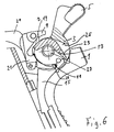
- This normal position of use of the trigger device is in FIG. 6 shown.
- the trigger device remains in the position shown in FIG. 5 is shown. If the trigger is now released and pulled again, then the hammer body 3, as described above, pivoted backwards. However, as with the automatic reloading, the drive part 17 with after behind. When you pull it off again, it is released and the Trigger device strikes again.
- a trigger rod 29 (Fig. 6) provided with a nose in the recess (coupling) 11 engages the hammer body 3 and this when the Deduction pivots into the position shown in FIG. 7.
- the Trigger bar 29 also serves by engaging in the Latch 21 trigger this to the tensioned drive part 17th to be knocked off.
- the trigger rod 29 engages with its nose free of play in the recess of the hammer body 3 a, which is referred to as coupling 11.
- the trigger rod 29 thus also actuates the pawl 21 when the hammer body 3 has taken the position of Fig. 7.
- the individual relative positions the elements of the trigger device are arranged so that the tensioned drive part 17, which when retracted Hammer body 3 is triggered, with a clear click in this can come up with. The deduction is made by the operator not touched.
- the hammer body 3 thus serves as a device for bracing the Drive part 17; however, this is not by means of the Hammer body can be tensioned, but only by means of the tension trigger.
Abstract
Description
Die Erfindung betrifft eine Spannabzugseinrichtung mit den folgenden Elementen:
- ein Hammerkörper, der
- -- zwischen einer vorderen und hinteren Endlage beweglich ist, und
- -- in der vorderen Endlage zum Aufschlag auf einen Schlagbolzen oder den Zündbereich einer Patrone eingerichtet ist,
- ein Antriebsteil, das zwischen einer vorderen Entspannungslage und einer hinteren Spannungslage beweglich ist und dazu eingerichtet ist, bei seiner Bewegung in die vordere Entspannungslage den Hammerkörper mitzunehmen,
- eine Schlagfeder, die das Antriebsteil in die Entspannungslage drückt, und
- ein Abzug, der
- -- die Bewegung des in der Entspannungslage befindlichen Antriebsteils gegen die Kraft der Schlagfeder in die Spannungslage und dann dessen Abschlagen in die Abspannungslage bewirkt, und
- -- bei unabhängig vom Abzug in die Spannungslage bewegtem
Antriebsteil dieses bis zum Betätigen des Abzugs in
dieser hält
(Oberbegriff des Anspruchs 1).
- a hammer body that
- - Is movable between a front and rear end position, and
- - is set up in the front end position to strike a firing pin or the ignition area of a cartridge,
- a drive part which is movable between a front relaxation position and a rear tension position and is designed to take the hammer body with it when it moves into the front relaxation position,
- a striking spring which presses the drive part into the relaxation position, and
- a deduction that
- - The movement of the drive part located in the relaxation position against the force of the impact spring in the tension position and then knocking it off in the tensioning position, and
- - When the drive part moves independently of the trigger in the voltage position, it holds it until the trigger is actuated
(Preamble of claim 1).
Eine solche Spannabzugseinrichtung ist besonders für Selbstladepistolen eingerichtet und ist durch die Selbstladepistole Daewoo DP 51 C bekannt.Such a clamping trigger device is particularly suitable for Self loading pistols set up and is by the Self-loading pistol known Daewoo DP 51 C.
Diese Pistole hat im Gegensatz zu einer üblichen Pistole, bei der der Hammerkörper und das Antriebsteil gemeinsam ein einziges Bauteil, den Hammer, bilden, keine ständig feste Verbindung zwischen dem Antriebsteil und dem Hammerkörper, der im übrigen als Hahn ausgebildet und mit einer Daumenauflage zum Spannen versehen ist. Der Hammerkörper ist vielmehr leicht reibungsgebremst, aber im übrigen frei schwenkbar im Griffstück gelagert und wird vom Antriebsteil nach vorne gedrückt.In contrast to a conventional pistol, this pistol comes with the hammer body and the drive part together are one Component, the hammer, do not form a permanent connection between the drive part and the hammer body, the rest designed as a cock and with a thumb rest for tensioning is provided. The hammer body is rather light slowed down, but otherwise freely pivotable in the handle stored and is pushed forward by the drive part.
Diese bekannte Pistole kann wie jede Double-Action-Pistole gebraucht werden: wenn das Antriebsteil ungespannt ist und sich der Hammerkörper in seiner Ruhelage befindet, dann bewegen sich durch Betätigung des Abzugs mit großer Kraft Hammerkörper und Antriebsteil nach hinten und schlagen dann ab. Hierdurch schlägt der Hammerkörper auf den Schlagbolzen auf und löst einen Schuß aus. Wenn bei ungespanntem Antriebsteil der Hammerkörper mittels seiner Handhabe von Hand oder durch den Verschluß der durchladenden Pistole nach hinten bewegt wird, dann bleiben Hammerkörper und Antriebsteil wie ein einziger Hahn beide in ihrer hinteren Endlage bzw. Spannungslage, bis der Abzug mit geringer Kraft abgezogen wird. Dies ist die voll gespannte Lage der Pistole.This well-known pistol can be used like any double-action pistol are needed: if the drive part is unstressed and up the hammer body is in its rest position, then move by pulling the trigger with great force Drive part to the rear and then knock off. This strikes the hammer body on the firing pin and releases a shot out. If the hammer body is unclamped using the his hand by hand or by closing the through-loading gun is moved backward, then stay Hammer body and drive part like a single tap both in their rear end position or tension position until the trigger with low force is withdrawn. This is the most tense situation the gun.
In diesem letztgenannten, gespannten Zustand der Abzugseinrichtung ist es aber auch möglich, den Hammerkörper nach vorne in seine Ruhelage zu schieben, während das Antriebsteil gespannt bleibt. Da der Hammerkörper sich in seiner Ruhelage befindet, kann die Pistole in einer Tasche oder einem Schulterhalfter verwahrt werden, ohne daß der abstehende Hammerkörper beim Ziehen der Pistole etwa am Deckel der Tasche oder am Stoff einer Jacke hängenbleibt. Soll geschossen werden, dann muß über den Abzug nicht mehr die Kraft zum Spannen der Schlagfeder aufgebracht werden. Vielmehr muß bis zum Erreichen des Druckpunktes nur der Reibungswiderstand des Hammerkörpers überwunden werden, der alleine nach hinten geschwenkt wird. Diese Stellung der Abzugseinrichtung könnte man als "Stellung erhöhter Bereitschaft" bezeichnen.In this latter, tense state of Trigger device, it is also possible, the hammer body to push forward to its rest position while the Drive part remains tensioned. Since the hammer body is in its The gun can be in a pocket or in a rest position Shoulder holsters are kept without the protruding Hammer body when pulling the gun around the lid of the bag or gets stuck on the fabric of a jacket. Should be shot then the trigger no longer needs the force to tension the Impact spring can be applied. Rather it has to be reached the pressure point only the frictional resistance of the hammer body overcome, which is pivoted backwards alone. This position of the trigger device could be called a "position increased readiness ".
Während in voll gespannter Lage, mit dem Hammerkörper nahe seiner hinteren Endlage, eine nur geringe Krafteinwirkung auf den Abzug ausreicht, um den Schuß auszulösen, muß in der "Stellung erhöhter Bereitschaft" noch die Reibungskraft des Hammerkörpers überwunden werden, so daß die Gefahr der ungewollten Abgabe eines Schusses verringert ist.While in a fully tensioned position, with the hammer body close its rear end position, only a small force the trigger sufficient to trigger the shot must be in the "Position of increased readiness" still the frictional force of the Hammer body to be overcome, so that the risk of unintended firing of a shot is reduced.
Allerdings ist es leicht möglich, daß durch Hängenbleiben mit der Handhabe an der Kleidung, an einem Zweig o. dgl. der Hammerkörper mehr oder weniger weit an seine hintere Endlage angenähert wird, so daß der Schütze zwar mit der "Stellung erhöhter Bereitschaft" rechnet, aber tatsächlich die voll gespannte Lage vorliegt. Die Gefahr der ungewollten Abgabe eines Schusses, die vermindert werden sollte, ist nun gerade gegeben.However, it is easy to get stuck with the handle on clothes, on a branch or the like Hammer body more or less far to its rear end position is approximated so that the shooter with the "position increased willingness "but actually the full tense situation. The risk of unwanted delivery of a Shot that should be reduced is now given.
Außerdem unterliegt die Reibungskraft in hohem Maße dem Zustand der Waffe; Abnutzung, Öl mit hoher Schmierwirkung oder Flugrost können diese Reibungskraft unter Umständen drastisch verändern, aber auch Staub, feiner Sand, Frost, der das Waffenschmieröl eindickt, o. dgl..In addition, the frictional force is largely subject to the condition the weapon; Wear, oil with a high lubricating effect or rust film can drastically change this frictional force, but also dust, fine sand, frost, which is the weapon lubricating oil thickened or the like
Schließlich ist die Bedienung dieser beschriebenen Waffe infolge der drei möglichen Zustände der Abzugseinrichtung kompliziert; bei einer Ordonnanzwaffe ist dagegen eine möglichst einfache Bedienung anzustreben. Vorteilhaft ist dagegen der einfache Aufbau der Spannabzugseinrichtung.Finally, the operation of this weapon is described as a result the three possible states of the trigger device complicated; an ordnance weapon, on the other hand, is as simple as possible To strive for operation. In contrast, the simple one is advantageous Structure of the clamping trigger device.
Um eine vergleichbare "Stellung erhöhter Bereitschaft" zu erreichen, ist in den EP-Patenten 0 077 790 und 0 154 356 vorgeschlagen, daß die Schlagfeder beim Durchladen einer Selbstladepistole nur teilweise gespannt werden soll, wie das auch bei der Österreichischen Kavalleriepistole Roth-Steyr Mod. 1907 der Fall ist, so daß der Schütze bei jedem Schuß zunächst die Schlagfeder über den Abzug voll spannen muß. In den obigen Patenten ist jedoch zusätzlich vorgeschlagen, daß eine Spannfeder der Schlagfeder so entgegenwirken soll, daß die zum Fertigspannen der Schlagfeder erforderliche Kraft teilweise von der Spannfeder aufgebracht wird. Bei voll gespannter Schlagfeder wird die Spannfeder abgekoppelt und der Schlagbolzen kann abschlagen.To a comparable "position of increased readiness" is achieved in EP patents 0 077 790 and 0 154 356 suggested that the striker when loading a Self-loading pistol should only be partially cocked, like that also with the Austrian cavalry pistol Roth-Steyr Mod. 1907 is the case, so that the shooter first with each shot the striker must fully tension the trigger. In the above However, it is additionally proposed that a Tension spring of the impact spring should counteract so that the Pre-tensioning of the striking spring partially requires force the tension spring is applied. With the spring fully cocked the tension spring is disconnected and the firing pin can knock off.
Abgesehen vom komplizierten und entsprechend verschmutzungs- und korrosionsgefährdeten Abkoppelmechanismus hat diese bekannte Pistole den Nachteil, daß sie ständig, wenn auch nur zum Teil, gespannt ist. Im unglücklichen Fall kann auch ein nur schwacher Schlagbolzenschlag ausreichen, um eine Patrone zu zünden, falls die sonstigen Sicherungsvorkehrungen versagen sollten.Apart from the complicated and accordingly pollution and Decoupling mechanism at risk of corrosion has this known Gun the disadvantage that it is constantly, if only partially, is excited. In the unfortunate case, even a weak one can Firing a firing pin is enough to fire a cartridge if the other safeguards should fail.
Ein weiterer Nachteil liegt in der Tatsache, daß zum Spannen des Schlagbolzens bis in die teilweise gespannte Lage stets die Verschlußbewegung erforderlich ist. Wenn beispielsweise bei nasser oder zu stark geölter Pistole der Schlag des Schlagbolzens durch eingedrungenes Wasser oder zu viel Öl in der Waffe abgebremst wird, dann kann es zum Versagen einer an sich fehlerfreien Patrone kommen. Wenn der Schütze nun nur eine Hand frei hat, weil er sich z.B. mit der anderen festhalten muß, dann kann er die Pistole nicht durchladen, so daß sie ausgefallen ist. Mit einem Spannabzug könnte er dagegen einfach nochmals abziehen, was im beschriebenen Fall mit hoher Wahrscheinlichkeit die Patrone zünden und die Pistole in ihre volle Bereitschaft zurückführen würde.Another disadvantage lies in the fact that to tension the Firing pin always in the partially tense position Closure movement is required. If, for example, at wet or over oiled pistol the blow of the Firing pin due to water penetration or too much oil in the Weapon is braked, then it can cause one in itself to fail error-free cartridge come. If the shooter now only one hand has free time because e.g. with the other, then he can’t load the pistol so it fails is. With a cocking trigger, however, it could simply be repeated deduct what is highly likely in the case described ignite the cartridge and the pistol in its full readiness would lead back.
Vorteilhaft dagegen ist der Umstand, daß der Abzugswiderstand durch Abstimmung der Spannfeder einstellbar ist, und daß beim Schuß immer die gleiche Betriebsart vorliegt.However, the fact that the trigger resistance is advantageous is adjustable by tuning the tension spring, and that at Shot always the same operating mode is present.
Ausgehend von der umrissenen Problemlage liegt der Erfindung die Aufgabe zugrunde, die eingangs genannte, bekannte Pistole dahingehend weiterzubilden, daß mindestens ein Teil der beschriebenen Nachteile des Standes der Technik ausgeräumt ist und eine Pistole geschaffen ist, die in der Handhabung möglichst einfach, sicher und zuverlässig ist. Based on the outlined problem, the invention is the The task is based on the well-known pistol mentioned at the beginning to further develop that at least part of the described disadvantages of the prior art is eliminated and a pistol is created that is as easy to handle as possible is simple, safe and reliable.
Diese Aufgabe wird dadurch gelöst, daß der Hammerkörper mit einer Feder verbunden ist, die ihn, solange der Abzug nicht betätigt ist, in eine Ruhelage drückt, die sich an oder nahezu an seiner vorderen Endlage befindet.This object is achieved in that the hammer body with a spring is connected to it as long as the trigger is not is pressed, presses into a rest position, which is at or almost located at its front end position.
Die Feder verbringt den Hammerkörper immer wieder in seine Ruhelage, wenn er durch Einwirkung von außen bewegt worden sein sollte. Eine "voll gespannte Lage", in der der Hammerkörper nach hinten geschwenkt bleibt, ist nicht möglich. Der Hammerkörper benötigt somit auch keine Handhabe, die nach hinten von der Waffe absteht, denn er bildet kein Bedienungselement der Waffe. Es ist sogar möglich, den Hammerkörper in das Innere der Waffe zu verlegen oder durch Blenden abzudecken, so daß er sich nicht, etwa beim Ziehen der Waffe, an irgendeinem Gegenstand verfangen kann.The spring keeps the hammer body in his Rest position if it has been moved by external influences should. A "fully tense position" in which the hammer body after remains pivoted at the rear is not possible. The hammer body therefore does not need a handle that is to the rear of the Weapon protrudes because it is not a control element of the weapon. It is even possible to put the hammer body inside the gun to lay or cover it with panels so that it does not for example, when pulling the gun, caught on something can.
Die Feder wirkt auch dem Abzug entgegen und deren Kraft ist bei jedem Schuß vom Abzug zu überwinden; die "Stellung erhöhter Bereitschaft" liegt bei funktionierender Munition ständig und als einzige Betriebsart vor, so daß die Bedienung erheblich erleichtert ist. Im Falle eines Patronenversagers kann aber die Möglichkeit des Spannabzuges benutzt werden. Soweit die Waffe mit einer zusätzlichen Abspanneinrichtung versehen ist, die das Antriebsteil abspannen kann, kann die Waffe auch völlig gespannt geführt und beim ersten Schuß mit dem Spannabzug betätigt werden.The spring also counteracts the trigger and its force is at to overcome every shot from the trigger; the "position elevated Readiness "lies with functioning ammunition constantly and as the only operating mode before, so that the operation considerably is relieved. In the case of a cartridge failure, however Possibility of tension deduction can be used. So much for the weapon is provided with an additional guy device that Can tension the drive part, the weapon can also be fully cocked out and operated with the trigger on the first shot become.
Die Kraft der Feder und damit die Abzugskraft, die vor jedem Schuß zu überwinden ist, kann in weiten Grenzen entsprechend der Bestimmung der Waffe optimiert oder sogar einstellbar ausgebildet werden. Diese Feder wirkt im übrigen in einer Richtung, die der der Spannfeder der Abzugseinrichtung der obengenannten Druckschriften entspricht, d.h. sie drückt den Hammerkörper nach vorne.The force of the spring and thus the pulling force before each Overcoming a shot can be done within a wide range Determination of the weapon optimized or even adjustable be formed. This spring acts in one Direction that of the tension spring of the trigger device corresponds to the above-mentioned documents, i.e. she presses it Hammer body forward.
So gelingt es der erfindungsgemäßen Spannabzugseinrichtung, die Vorzüge des Spannabzugs und des einfachen Aufbaus der gattungsbildenden Einrichtung mit dem abstimmbaren Abzugsgewicht und der einfachen Bedienung der Einrichtung nach einer der obengenannten Druckschriften zu vereinen, ohne deren Nachteile in Kauf nehmen zu müssen.The tension trigger device according to the invention thus succeeds in Advantages of the clamping trigger and the simple structure of the generic device with the tunable trigger weight and the simple operation of the device according to one of the to unite the above-mentioned publications without their disadvantages to have to put up with.
Eine mit der erfindungsgemäßen Abzugseinrichtung ausgestattete Pistole oder eine sonstige, moderne Handfeuerwaffe ist natürlich mit bekannten Sicherungseinrichtungen ausgestattet, die den Schlagbolzen festlegen, solange der Abzug nicht betätigt ist. Fällt beispielsweise die eingangs genannte, bekannte Pistole in entspanntem Zustand aus erheblicher Höhe mit dem Hammerkörper auf ein Straßenpflaster, so darf sich der Schuß nicht lösen. Diese Gefahr besteht allerdings nicht bei einem innenliegenden Hammerkörper.One equipped with the trigger device according to the invention Gun or other modern handgun is natural equipped with known security devices that the Set firing pin as long as the trigger is not actuated. For example, the known pistol mentioned at the beginning falls into relaxed state from a considerable height with the hammer body on a pavement, the shot must not come loose. However, this danger does not exist with an internal one Hammer body.
Dennoch ist jede zusätzliche Sicherung eine Verbesserung der Gesamtsicherheit, soweit nicht die Bedienungssicherheit und die Zuverlässigkeit darunter leidet.However, any additional backup is an improvement of the Overall security, unless the operational security and the Reliability suffers.
Deshalb wird gemäß Anspruch 2 vorteilhaft vorgeschlagen, daß das Antriebsteil in seiner Entspannungslage mindestens dann, wenn der Abzug nicht betätigt ist, auf einem Anschlag aufsitzt und von diesem in einer Lage gehalten ist, in der es das in seiner Endlage befindliche Schlagstück nicht berührt.Therefore, it is advantageously proposed according to claim 2 that the Drive part in its relaxation position at least if the trigger is not actuated, sits on a stop and is held by him in a position in which it is in his Impact end position not touched.
Hierbei wird der Hammerkörper vom Antriebsteil beschleunigt. Das Antriebsteil wird aber am Ende der Beschleunigungsphase vom Anschlag aufgehalten, während der Hammerkörper aufgrund seiner kinetischen Energie, die ihm vom Antriebsteil vermittelt wurde, sich bis zum Schlagbolzen weiterbewegt und auf diesen aufschlägt.Here, the hammer body is accelerated by the drive part. The Drive part is at the end of the acceleration phase from Stop stopped while the hammer body due to its kinetic energy imparted to him by the drive part moves on to the firing pin and on it hits.
Die Ruhelage des Hammerkörpers befindet sich jenseits des Anschlages, so daß das abschlagende Antriebsteil auf den in Ruhelage befindlichen Hammerkörper nicht aufschlagen kann, weil es vorher auf den Anschlag aufschlägt. Löst sich somit aus irgendeinem Grund das gespannte Antriebsteil, ohne daß der Abzug gezogen und somit der Hammerkörper aus seiner Ruhelage wegbewegt ist, dann kann das Antriebsteil den Hammerkörper nicht erreichen, so daß sich auch nicht ungewollt ein Schuß lösen kann.The rest position of the hammer body is beyond the Stop, so that the striking drive part on the in Hammer body located in the rest position cannot open because it hits the stop beforehand. This triggers for some reason the cocked drive part without the trigger pulled and thus the hammer body moved away from its rest position then the drive part cannot hit the hammer body reach, so that a shot is not accidentally released can.
Es ist aber auch erfindungsgemäß möglich (Anspruch 3), daß der Hammerkörper zusätzlich oder anstelle des soeben beschriebenen Anschlags eine Fangrast aufweist, die dann, wenn er sich nahe seiner vorderen Endstellung befindet, in ein in einer Fangposition befindliches Fangstück einfällt. Das Fangstück ist seinerseits so mit dem Abzug verbunden, daß ein Ziehen des Abzugs das Fangstück aus seiner Fangposition entfernt.But it is also possible according to the invention (claim 3) that the Hammer body in addition to or instead of the one just described Stop has a catch, which when it is close its front end position is in one in one Catch position located collapses. The catch piece is in turn so connected to the trigger that pulling the Trigger the catch piece removed from its catch position.
In seiner Ruhelage liegt der Hammerkörper mit seiner Fangrast auf dem Fangstück auf und kann sich nicht über diese hinaus bis in seine Endlage bewegen, in der er den Schlagbolzen erreichen kann.In its rest position, the hammer body lies with its catch stop on the catch piece and cannot extend beyond it move to its end position in which it can reach the firing pin can.
Wenn nun entweder das Antriebsteil anschlägt oder der Hammerkörper von außen her einen Schlag erhält, etwa wenn die Waffe herunterfällt, dann hält der Eingriff des Fangstücks in die Fangrast den Hammerkörper fest, so daß sich kein Schuß lösen kann. Auch wenn der Hammerkörper gegen die Einwirkung der ihn nach vorne in seine Ruhelage drückenden Feder nach hinten bewegt und losgelassen wird, schwenkt er lediglich wieder bis zu seiner Ruhelage, obwohl die Kraft dieser Feder ohnehin nicht ausreichen würde, damit ein Schlag auf den Schlagbolzen erfolgt, der zur Zündung einer Patrone ausreicht.If either the drive part strikes or the Hammer body receives a blow from the outside, for example when the Weapon falls, then the catch of the catch stops the catch catches the hammer body so that no shot is released can. Even if the hammer body against the action of him spring pressed forward into its rest position, moved backwards and is released, he just swings back to his Rest position, although the force of this spring is not sufficient anyway would, so that there is a blow to the firing pin, which is to Ignition of a cartridge is sufficient.
Es ist außerdem möglich, die Einwirkung der Feder auf den Hammerkörper so auszurichten, daß der Hammerkörper wie der Hahn eines Rückspringschlosses in der Ruhelage eine Totpunktlage einnimmt. Die Totpunktlage fällt mit der Lage zusammen , in welcher das Fangstück in die Fangrast einfällt. Wenn nun das Antriebsteil gespannt und der Abzug nicht betätigt ist, dann bewegt sich der Hammerkörper - sollte er sich in seiner vordersten Lage befinden - selbsttätig in seine Ruhelage zurück, in welcher die Fangrast wirksam ist. It is also possible to apply the spring to the Align the hammer body so that the hammer body is like the tap a snap lock in the rest position a dead center position occupies. The dead center position coincides with the position in which drops the catch into the catch. If so Drive part cocked and the trigger is not actuated, then the hammer body moves - should it move in its are in the foremost position - automatically return to its rest position, in which the catch rest is effective.
Die Feder, die den Hammerkörper in seiner Ruhelage hält, kann eine unabhängige, zwischen dem Hammerkörper und dem Waffengehäuse angebrachte Zug- oder Druckfeder sein.The spring that holds the hammer body in its rest position can an independent, between the hammer body and the Gun housing attached tension or compression spring.
Bevorzugt (Anspruch 4) ist jedoch erfindungsgemäß die Feder von der Abzugsfeder gebildet oder als solche wirksam, die den Abzug ständig nach vorne drückt. Es liegt also entweder eine Feder vor, die unmittelbar auf den Hammerkörper einwirkt, der seinerseits aufgrund seiner Verbindung mit dem Abzug diesen nach vorne drückt, oder dem Abzug ist, wie üblich, eine Feder zugeordnet, die ihn nach vorne drückt, und der Abzug seinerseits wirkt etwa über eine Stange auf den Hammerkörper ein und verbringt diesen in eine ihm zugeordnete Lage.According to the invention, however, the spring of is preferred the trigger spring is formed or effective as such, the trigger constantly pushes forward. So there is either a feather before, which acts directly on the hammer body, the in turn due to its connection with the deduction pushes in front, or the trigger is, as usual, a spring assigned, which pushes him forward, and the deduction in turn acts on the hammer body via a rod and puts him in a position assigned to him.
Es ist sogar möglich, in den Abzug einen Sicherungsauslöser zu integrieren, der den Abzug blockiert, solange nicht der den Abzug betätigende Finger den Sicherungsauslöser eindrückt, der an der Stirnfläche des Abzugs angeordnet ist. Daher verbleibt der Hammerkörper fest in seiner Ruhelage, solange nicht der Abzug betätigt wird. Auch eine äußere Einwirkung auf den Hammerkörper kann diesen nicht aus der Ruhelage bewegen.It is even possible to have a fuse trigger in the trigger integrate who blocks the trigger as long as not the Trigger pulls the fuse release that is arranged on the end face of the trigger. Therefore remains the hammer body firmly in its rest position, as long as not the Trigger is operated. Also an external influence on the The hammer body cannot move it from the rest position.
Die mit der erfindungsgemäßen Spannabzugseinrichtung ausgestattete Waffe kann zusätzliche Einrichtungen aufweisen die von anderen Waffen her bekannt sind. Besonders bevorzugt ist eine an sich bekannte Abspanneinrichtung zum Abspannen des Antriebsteiles (Anspruch 5).The with the cocking device according to the invention equipped weapon can have additional facilities are known from other weapons. Is particularly preferred a known guy device for guying the Drive part (claim 5).
Mittels dieser Abspanneinrichtung kann das Antriebsteil abgespannt werden. Soll in diesem abgespannten Zustand geschossen werden, dann kann zunächst der Spannabzug betätigt werden. Wenn der Hammerkörper eine Handhabe aufweist, ist es aber auch möglich, daß man z.B. mit dem Daumen die Handhabe des Hammerkörpers ergreift und den Hammerkörper und damit das auf ihm von hinten her aufliegende Antriebsteil nach hinten schwenkt, bis das Antriebsteil in gespannter Lage einrastet. Nun läßt man den Hammerkörper wieder nach vorne bewegen, und die Waffe befindet sich in erhöhter Feuerbereitschaft. By means of this guy device, the drive part be braced. Should be in this tensioned state can be shot, then the cocking trigger can be operated first become. If the hammer body has a handle, it is but it is also possible that e.g. with the thumb the handle of the Grips the hammer body and the hammer body and thus on drive part lying on it from behind towards the rear swivels until the drive part engages in the tensioned position. Now you can move the hammer body forward again, and the The weapon is on fire.
Der Hammerkörper ist, wie schon erwähnt, mit dem Abzug gekoppelt, so daß das Ziehen des Abzuges eine Schwenkbewegung des Hammerkörpers veranlaßt, der etwa nach einem Patronenversager das dann abgespannte Antriebsteil mitnehmen kann. Diese Koppelung wird durch eine Abzugsstange ausgeführt, die auch mit der Rastklinke gekoppelt ist, so daß bei Betätigung des Abzugs und somit der Abzugsstange diese das gespannte Spannteil ausgelöst.As already mentioned, the hammer body is with the trigger coupled so that pulling the trigger pivots causes the hammer body, which after about one Cartridge failure take the tensioned drive part with them can. This coupling is carried out by a trigger rod, which is also coupled to the latch, so that when actuated the trigger and thus the trigger rod this the cocked Clamping part triggered.
In herkömmlicher Ausgestaltung ist die Abzugsstange jedoch nur in Spannrichtung mit dem Hammerkörper voll gekoppelt; wird dagegen der Hammerkörper von Hand zurückbewegt, folgt die Abzugsstange der Bewegung des Hammerkörpers nur teilweise, so daß die Rast des Antriebsteils in die zugehörige Rastklinke einfallen kann. Auf diese Weise kann das Antriebsteil, wenn es aus irgendeinem Grund entspannt ist, wieder gespannt werden.In a conventional embodiment, however, the trigger rod is only fully coupled in the clamping direction with the hammer body; becomes on the other hand, the hammer body is moved back by hand, follows Trigger bar of the movement of the hammer body only partially, see above that the rest of the drive part in the associated latch can come up with. In this way, the drive part when it relaxed for some reason, be excited again.
Zum Entspannen des Antriebsteils dient die obenerwänte Abspanneinrichtung.The above-mentioned is used to relax the drive part Guy device.
Als Alternativlösung ist gemäß Anspruch 6 die Abzugsstange jedoch ständig eindeutig mit dem Hammerkörper spielfrei gekoppelt, so daß jeder Lage des Hammerkörpers eine zugehörige Lage der Abzugseinrichtung zugeordnet werden kann, und umgekehrt. Zu diesem Zweck ist eine Ausnehmung im Hammerkörper vorgesehen, in die eine an der Abzugsstange ausgebildete Nase eingreift, oder eine Bohrung im Hammerkörper, in die ein Zapfen der Abzugsstange eingreift, oder dergleichen.As an alternative solution is the trigger rod according to claim 6 but always clearly free of play with the hammer body coupled so that each position of the hammer body has an associated Location of the trigger device can be assigned, and vice versa. For this purpose there is a recess in the hammer body provided in the one formed on the trigger rod nose engages, or a hole in the hammer body, in which a pin the trigger rod engages, or the like.
Wird nun der Hammerkörper mittels seiner Handhabe nach hinten geschwenkt, während das Antriebsteil gespannt ist, dann wird gleichzeitig die Abzugsstange bewegt, bis die Rast des Antriebsteils ausgelöst wird. Dabei sind die Betriebsstellungen aller Elemente so abgestimmt, daß das Antriebsteil nach seinem Auslösen sich ein wenig nach vorne bewegt und dann in den Hammerkörper einfällt. Dieser Vorgang ist durch ein deutliches Klicken vernehmbar. Der Hammerkörper bewegt sich, wenn nun die Handhabe losgelassen oder mit dem Daumen langsam nach vorne gelassen wird, zusammen mit dem Antriebsteil nach vorne, bis die Fangrast den Hammerkörper vor Erreichen des Schlagbolzens anhält; die Fangrast ist aber wirksam, weil der Abzug nicht gezogen ist. So wirkt die erfindungsgemäße Weiterbildung als Abspanneinrichtung. Ein Spannen des Antriebsteils durch Betätigen des Hammerkörpers ist nicht möglich; bei abgespanntem Antriebsteil erfolgt der erste Schuß mittels der (hier nicht näher erläuterten) Spannabzugseinrichtung. Wenn die Rastklinke und die Fangklinke durch Betätigen des Abzugs zurückgezogen sind und das Antriebsteil (zusammen mit dem Hammerkörper) abschlägt, dann wird die Verbindung zwischen Abzug und Abzugsstange gelöst, so daß sich diese zusammen mit dem Hammerkörper bewegen kann, ohne daß sich auch der Abzug bewegen muß.Now the hammer body is moved backwards using its handle swiveled while the drive part is tensioned, then at the same time the trigger rod moves until the catch of the Drive part is triggered. Here are the operating positions all elements matched so that the drive part according to his Trigger yourself moving a little forward and then into the Hammer body occurs. This process is clear Click audible. The hammer body moves when the Let go of the handle or slowly push your thumb forward is left together with the drive part forward until the Catch the hammer body before reaching the firing pin persists; the catch stop is effective because the deduction is not is drawn. So the training according to the invention acts as Guy device. A tensioning of the drive part It is not possible to operate the hammer body; with tensioned Drive part, the first shot is made using the (not here explained) clamping trigger device. When the pawl and the catch is pulled back by pulling the trigger and knocks off the drive part (together with the hammer body), then the connection between trigger and trigger rod is released, so that it can move together with the hammer body, without the trigger also having to move.
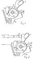
Der Gegenstand der Erfindung wird anhand der beigefügten, schematischen Zeichnung beispielsweise noch näher erläutert. In dieser ist eine schematische Darstellung einzelner Teile der erfindungsgemäßen Spannabzugseinrichtung in gegenseitiger Zuordnung und in verschiedenen Stellungen in Seitenansicht gezeigt. Die einzelnen Figuren zeigen:
- Fig. 1
- den Hammerkörper in Ruhelage und in Eingriff mit der Fangklinke,
- Fig. 2
- den Hammerkörper in seiner vorderen Endlage, mit freigegebener Fangrast,
- Fig. 3
- das gespannte Antriebsteil, mit Rastklinke und Federstange,
- Fig. 4
- eine Darstellung wie in Fig. 3, jedoch mit entspanntem Antriebsteil,
- Fig. 5
- den Hammerkörper in der Lage der Fig. 2 und das Antriebsteil in der Lage der Fig. 4,
- Fig. 6
- den Hammerkörper in der Lage der Fig. 1 und das Antriebsteil in der Lage der Fig. 3, und
- Fig. 7
- den Hammerkörper und das Antriebsteil unmittelbar vor dem Auslösen.
- Fig. 1
- the hammer body in the rest position and in engagement with the catch,
- Fig. 2
- the hammer body in its front end position, with released catch,
- Fig. 3
- the tensioned drive part, with latch and spring rod,
- Fig. 4
- a representation as in Fig. 3, but with the drive part relaxed,
- Fig. 5
- the hammer body in the position of FIG. 2 and the drive member in the position of FIG. 4,
- Fig. 6
- the hammer body in the position of FIG. 1 and the drive member in the position of FIG. 3, and
- Fig. 7
- the hammer body and the drive part immediately before triggering.
In diesen Unterlagen verwendete Lagebezeichnungen wie "vorne", "oben" o.dgl. beziehen sich auf die Lage der Abzugseinrichtung, die sie dann einnimmt, wenn die dazugehörige Waffe sich in Schußposition mit horizontaler Seelenachse befindet; "vorne" weist dabei in Schußrichtung. In der Zeichnung ist "vorne" gleichbedeutend mit links, und "oben" ist gleichbedeutend mit "oben".Positional designations such as "front" used in these documents, "above" or the like relate to the location of the fume cupboard, which it assumes when the associated weapon is in Shot position with horizontal soul axis; "front" points in the direction of the shot. In the drawing is "front" synonymous with left, and "above" is synonymous with "above".
In allen Zeichnungen sind durchgehend dieselben Bezugszeichen für dieselben Elemente verwendet.The same reference numbers are used throughout the drawings used for the same elements.
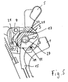
In der Zeichnung ist der hintere Abschnitt eines Griffstücks 1
im schematischen Schnitt zu sehen. Das Griffstück ist quer von
einer Achse 27 durchsetzt, auf der schwenkbar ein Hammerkörper 3
und ein Antriebsteil 17 gelagert sind.In the drawing, the rear section of a
Der auf der Achse 27 gelagerte Teil des Hammerkörpers 3 weist
eine sich von unten her und in Längsrichtung des Griffstücks 1
erstreckende Aussparung auf, die in einer Gegenfläche 25 endet.
In der Aussparung ist das Antriebsteil 17 angeordnet, das eine
mit der Gegenfläche 25 in Eingriff bringbare Anlagefläche 23
aufweist. Bei einer Schwenkbewegung des Antriebsteils 17
entgegen dem Uhrzeigersinn legt sich die Anlagefläche 23 gegen
die Gegenfläche 25 an und nimmt so den Hammerkörper 3 mit.The part of the
Der Hammerkörper 3 weist ferner eine nach oben abstehende
Handhabe 5 auf, die der Schütze mit dem Daumen ergreifen kann.
Zudem eine Fangrast 7 und eine Ankoppelungsausbildung 11, durch
welche der Hammerkörper 3 durch (nicht gezeigte
Zwischenelemente) in Verbindung mit dem (nicht gezeigten) Abzug
bringbar ist. The
In der Ruhelage des Hammerkörpers 3, der Fangrast 7
gegenüberliegend, befindet sich eine schwenkbar am Griffstück 1
gelagerte Fangklinke 9, die in dieser Ruhelage in die Fangrast 7
einfallen kann. Die Fangklinke 9 verhindert dann eine weitere
Schwenkbewegung des Hammerkörpers 3 entgegen dem Uhrzeigersinn .In the rest position of the
Vor der Handhabe 5 des Hammerkörpers 3 befindet sich das hintere
Ende eines Schlagbolzens 13 in einer solchen Lage, daß es vom
Hammerkörper 3 in dessen Ruhelage nicht berührt werden kann.In front of the
Das Antriebsteil 17 ist innerhalb der Aussparung des
Hammerkörpers 3 angeordnet und ebenfalls auf der Achse 27
drehbar gelagert. Es wird durch eine Federstange 15, die von
einer (nicht gezeigten) Schlagfeder nach oben gedrückt wird, in
einer Richtung entgegen dem Uhrzeigersinn belastet. Das
Antriebsteil 17 weist ferner eine Rast bzw. eine Raststufe 19
auf, in die eine Rastklinke 21 einfallen kann, wenn sich das
Antriebsteil 17 in seiner Spannlage befindet.The
Die Fangklinke 9 und die Rastklinke 21 stehen beide mit dem
(nicht gezeigten) Abzug so in Verbindung, daß beide Klinken 9,
21 aus dem Eingriff mit dem Hammerkörper 3 bzw. dem Antriebsteil
17 geschwenkt werden, wenn der Abzug gezogen wird. Ein
Unterbrecher (nicht gezeigt) sorgt dafür, daß bei noch immer
gezogenem Abzug - wenn aber infolge eines Nachladevorganges das
Antriebsteil 17 wieder gespannt ist - auch die beiden Klinken 9,
21 in ihre Ausgangslage zurückgekehrt sind. Dabei hindern sie
den Hammerkörper 3 und das Antriebsteil 17 an einer
Schwenkbewegung entgegen dem Uhrzeigersinn.The
Die Wirkungsweise der gezeigten Abzugseinrichtung ist wie folgt:The fume cupboard shown works as follows:
In Fig. 1 ist der Hammerkörper 3 in seiner Ruhelage gezeigt. Die
Fangklinke 7 greift in die Fangrast 7 ein und verhindert eine
weitere Vorwärtsbewegung des Hammerkörpers 3, der somit den
Schlagbolzen 13 (Fig. 2) nicht erreichen kann. Die Abzugsfeder
(nicht gezeigt) wirkt über die Ankoppelung 11 auf den
Hammerkörper 3 ein und drückt ihn nach vorne. Es ist zwar
möglich, den Hammerkörper 3 mittels der Handhabe 5 nach hinten
zu schwenken, weil die Fangrast 7 nur die Schwenkbewegung zum
Schlagbolzen 13 hin, aber nicht von diesem weg verhindert. Der
Hammerkörper 3 kehrt jedoch immer wieder in die gezeigte
Ruhelage zurück.In Fig. 1 the
Wird der Abzug abgezogen, dann wird die Fangklinke 9 aus dem
Eingriff mit der Fangrast geschwenkt. Nun kann der Hammerkörper
3 den Schlagbolzen 13 erreichen (Fig. 2).If the trigger is withdrawn, then the
Ist das Antriebsteil 17 gegen die Kraft, die von der Federstange
15 nach oben ausgeübt wird, nach hinten geschwenkt, dann fällt
die Rast 19 in die Rastklinke 21 ein und das Antriebsteil 17
verbleibt in der gespannten Lage. Wird der Abzug gezogen, dann
wird der Hammerkörper 3 nach hinten geschwenkt und die Klinken 9
und 21 werden gemeinsam im Uhrzeigersinn geschwenkt. Hierdurch
wird das Antriebsteil 17 freigegeben, das dann, durch die Kraft
der Federstange 15 energisch angetrieben, nach vorne schwenkt
und dabei den sich hinten befindlichen Hammerkörper 3 mitnimmt,
weil die Anlagefläche 23 des Antriebsteils 17 auf die
Gegenfläche 25 des Hammerkörpers 3 auftrifft. Der Hammerkörper 3
wird kraftvoll nach vorne geschlagen (Fig. 5), bis er auf den
Schlagbolzen 13 aufschlägt. Dies ist möglich, weil, wie schon
erwähnt, die Fangklinke 9 aufgrund des gezogenen Abzugs
ebenfalls zurückgeschwenkt ist.Is the
Beim nachfolgenden Schuß wirkt der entstehende Rückstoß über
einen Verschluß (nicht gezeigt) auf die Handhabe 5 des
Hammerkörpers 3 ein und schwenkt diesen zurück. Dabei drückt die
Gegenfläche 25 auf die Anlagefläche 23 des Antriebsteils 17 und
spannt dieses, bis seine Rast 19 in die Rastklinke 21 einfällt
und das Antriebsteil 17 in der Spannlage gehalten wird. Gleitet
der Verschluß dann wieder nach vorne, so kann auch der
Hammerkörper 3, der von seiner Feder über die Ankoppelung 11 mit
geringer Kraft angetrieben ist, wieder sanft nach vorne fallen,
bis die Fangrast 7 auf die Fangklinke 9 aufsetzt. The resulting recoil acts on the following shot
a closure (not shown) on the
Während des beschriebenen Vorgangs ist der Abzug zwar noch immer
gezogen, aber mittels einer Unterbrechungseinrichtung
abgekoppelt. Die Klinken 9 und 21 verhalten sich dabei so, als
wäre der Abzug nicht betätigt.The deduction is still in process
drawn, but by means of an interruption device
uncoupled. The
Diese normale Gebrauchslage der Abzugseinrichtung ist in Fig. 6 gezeigt.This normal position of use of the trigger device is in FIG. 6 shown.
Wird nun der Abzug gezogen, dann wird zunächst der Hammerkörper
3 nach hinten geschwenkt, bis die Klinken 9 und 21 verschwenkt
werden und das oben beschriebene Abschlagen erfolgen kann. Der
Zustand kurz vor dem Abschlagen ist in Fig. 7 gezeigt.If the trigger is now pulled, the hammer body is first
3 pivoted backwards until the
Wenn nach dem Abschlagen keine Zündung der Patrone erfolgt,
verbleibt die Abzugseinrichtung in der Stellung, die in Fig. 5
gezeigt ist. Wird nun der Abzug losgelassen und wieder gezogen,
dann wird durch diesen der Hammerkörper 3, wie oben beschrieben,
nach hinten geschwenkt. Er nimmt allerdings nun, wie beim
selbsttätigen Nachladevorgang, das Antriebsteil 17 mit nach
hinten. Beim weiteren Abziehen wird diese freigegeben, und die
Abzugseinrichtung schlägt erneut ab.If the cartridge does not ignite after knocking off,
the trigger device remains in the position shown in FIG. 5
is shown. If the trigger is now released and pulled again,
then the
Für Anschlagübungen, bei denen sich im Patronenlager des Laufes
keine Patrone oder eine leere Patronenhülse oder eine
Pufferpatrone befindet, ist es möglich, nach jedem Abschlagen
den Abzug loszulassen und dann mittels der Handhabe 5 den
Hammerkörper 3 nach hinten zu schwenken, der dabei das
Antriebsteil 17 mitnimmt und spannt. Anschließend läßt man den
Hammerkörper 3 los, der nach vorne bis zur Auflage seiner
Fangrast 7 auf der Fangklinke 9 schnappt. Nun kann wiederum das
Abziehen geübt werden.For striking exercises where the barrel is in the cartridge chamber
no cartridge or an empty cartridge case or one
Buffer cartridge is located, it is possible to knock after each
Let go of the trigger and then 5 by means of the handle
Swing the
Bei der beschriebenen Ausführung ist eine Abzugsstange 29 (Fig.
6) vorgesehen, die mit einer Nase in die Ausnehmung (Koppelung)
11 des Hammerkörpers 3 eingreift und diesen bei Betätigung des
Abzugs in die in Fig. 7 gezeigte Lage schwenkt. Die
Abzugsstange 29 dient auch dazu, durch ihren Eingriff in die
Rastklinke 21 diese auszulösen, um das gespannte Antriebsteil 17
abschlagen zu lassen.In the described embodiment, a trigger rod 29 (Fig.
6) provided with a nose in the recess (coupling)
11 engages the
Hierbei besteht ein gewisses Spiel zwischen Hammerkörper 3 und
Abzugsstange 29, so daß sich dann, wenn der Hammerkörper 3 von
Hand in die in Fig. 7 gezeigte Lage nach hinten geschwenkt wird,
noch kein Auslösen des Antriebsteils 17 erfolgt.There is some play between
Gemäß einer Variante greift die Abzugsstange 29 (Fig. 6) jedoch
mit ihrer Nase spielfrei in die Ausnehmung des Hammerkörpers 3
ein, die als Koppelung 11 bezeichnet ist. Die Abzugsstange 29
betätigt somit auch die Rastklinke 21, wenn der Hammerkörper 3
die Lage der Fig. 7 eingenommen hat. Die einzelnen Relativlagen
der Elemente der Abzugseinrichtung sind dabei so angeordnet, daß
das gespannte Antriebsteil 17, das bei zurückgezogenem
Hammerkörper 3 ausgelöst wird, mit deutlichem Klicken in diesen
einfallen kann. Der Abzug wird dabei von der Bedienungsperson
nicht berührt.According to a variant, however, the trigger rod 29 (FIG. 6) engages
with its nose free of play in the recess of the hammer body 3
a, which is referred to as
Wird der Hammerkörper 3 nun nach vorne gelassen oder einfach
losgelassen, dann bewegt er sich unter der Last des
Antriebsteils 17, bis die Fangrast 9 des Hammerkörpers 3 auf die
Fangklinke 9 aufläuft. Der Schlagbolzen 13 wird dabei nicht
berührt.If the
Der Hammerkörper 3 dient somit als Einrichtung zum Abspannen des
Antriebsteils 17; dieses ist allerdings nicht mittels des
Hammerkörpers spannbar, sondern nur mittels des Spannabzugs.The
Claims (6)
Applications Claiming Priority (2)
| Application Number | Priority Date | Filing Date | Title |
|---|---|---|---|
| DE19732857A DE19732857C1 (en) | 1997-07-30 | 1997-07-30 | Safety action e.g. for rifle |
| DE19732857 | 1997-07-30 |
Publications (3)
| Publication Number | Publication Date |
|---|---|
| EP0895053A2 true EP0895053A2 (en) | 1999-02-03 |
| EP0895053A3 EP0895053A3 (en) | 2000-08-23 |
| EP0895053B1 EP0895053B1 (en) | 2003-07-16 |
Family
ID=7837394
Family Applications (1)
| Application Number | Title | Priority Date | Filing Date |
|---|---|---|---|
| EP98107965A Expired - Lifetime EP0895053B1 (en) | 1997-07-30 | 1998-04-30 | Double action trigger mechanism |
Country Status (8)
| Country | Link |
|---|---|
| US (1) | US5915935A (en) |
| EP (1) | EP0895053B1 (en) |
| KR (1) | KR100360014B1 (en) |
| AT (1) | ATE245274T1 (en) |
| CA (1) | CA2244319C (en) |
| DE (2) | DE19732857C1 (en) |
| DK (1) | DK0895053T3 (en) |
| ES (1) | ES2201369T3 (en) |
Cited By (1)
| Publication number | Priority date | Publication date | Assignee | Title |
|---|---|---|---|---|
| EP0982557A3 (en) * | 1998-08-24 | 2000-11-15 | Angelotti Inc. | Double action pistol |
Families Citing this family (9)
| Publication number | Priority date | Publication date | Assignee | Title |
|---|---|---|---|---|
| DE19959964C5 (en) * | 1999-12-13 | 2009-01-08 | Heckler & Koch Gmbh | backup |
| DE10014687C1 (en) * | 2000-03-24 | 2001-07-26 | Heckler & Koch Gmbh | Hand gun with clamping-piece safety lock, includes lock independent of trigger mechanism for selective operation of clamping piece |
| DE102004032309B4 (en) * | 2004-07-03 | 2010-04-08 | Carl Walther Gmbh | firearm |
| DE102005046877B4 (en) * | 2004-09-29 | 2008-05-15 | Carl Walther Gmbh | Gun trigger device |
| US20060207147A1 (en) * | 2005-03-19 | 2006-09-21 | Lazor Ernest R | Self-contained triggerplate action for low profile firearms |
| ATE436002T1 (en) | 2006-07-11 | 2009-07-15 | Sat Swiss Arms Technology Ag | TRIGGER DEVICE FOR HAND GUNS |
| DE102007004588B3 (en) * | 2007-01-30 | 2008-07-24 | Heckler & Koch Gmbh | Control element for impact lever of weapon moving around swivel axis, has control cam area, which is adjacent to control cam section in turn direction in adjustable manner |
| CN104154812B (en) * | 2014-07-31 | 2016-02-10 | 浙江新华机械制造有限公司 | A kind of baton gun with fall insurance structure |
| WO2020264508A1 (en) | 2019-06-27 | 2020-12-30 | Sturm, Ruger & Company, Inc. | Safety mechanism for firearms |
Citations (1)
| Publication number | Priority date | Publication date | Assignee | Title |
|---|---|---|---|---|
| EP0077790A1 (en) | 1981-04-30 | 1983-05-04 | Gaston Glock | Gun. |
Family Cites Families (11)
| Publication number | Priority date | Publication date | Assignee | Title |
|---|---|---|---|---|
| US3726040A (en) * | 1970-06-10 | 1973-04-10 | Rolamite Inc | Gun trigger mechanism |
| DE2517002A1 (en) * | 1975-04-17 | 1976-10-28 | Walther Carl Gmbh | CLAMPING MECHANISM FOR HANDGUN |
| IT1090110B (en) * | 1977-10-28 | 1985-06-18 | Beretta Armi Spa | AUTOMATIC PERFECTED GUN |
| BE876396R (en) * | 1979-01-10 | 1979-11-21 | Herstal Sa | PERFECTED GUN |
| SE8105054L (en) * | 1980-08-27 | 1982-02-28 | Dal David John Van | DEVICE OF COMBUSTION ENGINE |
| IT1133775B (en) * | 1980-11-10 | 1986-07-09 | Franchi Spa Luigi | SAFETY DEVICE FOR SHOOTING MECHANISMS OF A GAS-PUMP TYPE HUNTING LINE |
| US4706401A (en) * | 1981-03-10 | 1987-11-17 | Nielsen Bent A | Trigger mechanism for a weapon |
| DE3332792A1 (en) * | 1983-09-10 | 1985-03-28 | Bayer Ag, 5090 Leverkusen | USE OF POLYHYDROXYALKYL-POLYCARBONAMIDES FOR THE PRODUCTION OF FLAME-PROTECTED POLYURETHANE HARD FOAM AND INTEGRAL FOAMS |
| US5166458A (en) * | 1991-01-11 | 1992-11-24 | Daewoo Precision Ind., Ltd. | Firing mechanism for fast shooting pistol |
| EP0540778A1 (en) * | 1991-11-08 | 1993-05-12 | ITM INDUSTRIAL TECHNOLOGY & MACHINES AG | Trigger mechanism for firearms |
| IL100548A0 (en) * | 1991-12-30 | 1992-09-06 | Israel Military Ind | Double action pistol with improved firing mechanism |
-
1997
- 1997-07-30 DE DE19732857A patent/DE19732857C1/en not_active Expired - Fee Related
-
1998
- 1998-04-30 EP EP98107965A patent/EP0895053B1/en not_active Expired - Lifetime
- 1998-04-30 DE DE59809012T patent/DE59809012D1/en not_active Expired - Lifetime
- 1998-04-30 DK DK98107965T patent/DK0895053T3/en active
- 1998-04-30 AT AT98107965T patent/ATE245274T1/en active
- 1998-04-30 ES ES98107965T patent/ES2201369T3/en not_active Expired - Lifetime
- 1998-07-29 US US09/124,824 patent/US5915935A/en not_active Expired - Lifetime
- 1998-07-29 CA CA002244319A patent/CA2244319C/en not_active Expired - Fee Related
- 1998-07-29 KR KR10-1998-0030582A patent/KR100360014B1/en not_active IP Right Cessation
Patent Citations (2)
| Publication number | Priority date | Publication date | Assignee | Title |
|---|---|---|---|---|
| EP0077790A1 (en) | 1981-04-30 | 1983-05-04 | Gaston Glock | Gun. |
| EP0154356A2 (en) | 1981-04-30 | 1985-09-11 | Gaston Glock | Pistol |
Cited By (1)
| Publication number | Priority date | Publication date | Assignee | Title |
|---|---|---|---|---|
| EP0982557A3 (en) * | 1998-08-24 | 2000-11-15 | Angelotti Inc. | Double action pistol |
Also Published As
| Publication number | Publication date |
|---|---|
| ATE245274T1 (en) | 2003-08-15 |
| ES2201369T3 (en) | 2004-03-16 |
| KR100360014B1 (en) | 2003-01-24 |
| EP0895053B1 (en) | 2003-07-16 |
| KR19990014272A (en) | 1999-02-25 |
| DE59809012D1 (en) | 2003-08-21 |
| EP0895053A3 (en) | 2000-08-23 |
| DK0895053T3 (en) | 2003-11-10 |
| CA2244319A1 (en) | 1999-01-30 |
| US5915935A (en) | 1999-06-29 |
| DE19732857C1 (en) | 1998-10-08 |
| CA2244319C (en) | 2002-04-02 |
Similar Documents
| Publication | Publication Date | Title |
|---|---|---|
| EP0816792B1 (en) | Trigger mechanism | |
| DE69631771T2 (en) | FENCING MECHANISM FOR AN AUTOMATIC PISTOL | |
| DE102013022080B3 (en) | Device for preventing tightening of firing pin spring of self-loading gun, has trigger rod which is coupled to breaker bar that is acted in disassembly position by moving closing slide, so that catch pawl is engaged with projection | |
| DE2442107A1 (en) | SEMI-AUTOMATIC FIRE ARM | |
| EP1181495B1 (en) | Hand firearm with safety device for a tensioning element | |
| EP1119736B1 (en) | Trigger device | |
| DE19812951C2 (en) | Firing pin safety in the lock | |
| EP0895053B1 (en) | Double action trigger mechanism | |
| DE2745670A1 (en) | TRIGGER SAFETY FOR GUNS | |
| DE844558C (en) | Automatic firearm with one-piece breech | |
| DE10163003B4 (en) | Trigger device for a rapid-fire handgun | |
| DE2754761C2 (en) | "Trigger device for a semi-automatic firearm" | |
| CH620987A5 (en) | ||
| CH626717A5 (en) | Automatic firearm | |
| DE605729C (en) | Handgun with a cocked trigger | |
| AT15968B (en) | Automatic cartridge feed for rapid fire guns. | |
| DE19810787B4 (en) | Lock with security and Rückstecher | |
| DE1148470B (en) | Automatic firearm with a changeover device for single and continuous fire | |
| DE294954C (en) | ||
| DE318564C (en) | ||
| DE1428772C (en) | Firing automatic handgun | |
| DE1453917A1 (en) | Shooting automatic handgun | |
| DE19839985A1 (en) | Self-loading handgun with a lock catch that can also be activated independently of the magazine | |
| DE1294269B (en) | Servo trigger for automatic weapons | |
| DE1453921A1 (en) | Automatic hunting rifle |
Legal Events
| Date | Code | Title | Description |
|---|---|---|---|
| PUAI | Public reference made under article 153(3) epc to a published international application that has entered the european phase |
Free format text: ORIGINAL CODE: 0009012 |
|
| AK | Designated contracting states |
Kind code of ref document: A2 Designated state(s): AT BE CH DE DK ES FR GB IT LI NL |
|
| AX | Request for extension of the european patent |
Free format text: AL;LT;LV;MK;RO;SI |
|
| PUAL | Search report despatched |
Free format text: ORIGINAL CODE: 0009013 |
|
| AK | Designated contracting states |
Kind code of ref document: A3 Designated state(s): AT BE CH CY DE DK ES FI FR GB GR IE IT LI LU MC NL PT SE |
|
| AX | Request for extension of the european patent |
Free format text: AL;LT;LV;MK;RO;SI |
|
| 17P | Request for examination filed |
Effective date: 20000926 |
|
| AKX | Designation fees paid |
Free format text: AT BE CH DE DK ES FR GB IT LI NL |
|
| GRAH | Despatch of communication of intention to grant a patent |
Free format text: ORIGINAL CODE: EPIDOS IGRA |
|
| GRAH | Despatch of communication of intention to grant a patent |
Free format text: ORIGINAL CODE: EPIDOS IGRA |
|
| GRAA | (expected) grant |
Free format text: ORIGINAL CODE: 0009210 |
|
| AK | Designated contracting states |
Designated state(s): AT BE CH DE DK ES FR GB IT LI NL |
|
| REG | Reference to a national code |
Ref country code: GB Ref legal event code: FG4D Free format text: NOT ENGLISH |
|
| REG | Reference to a national code |
Ref country code: CH Ref legal event code: EP |
|
| GBT | Gb: translation of ep patent filed (gb section 77(6)(a)/1977) |
Effective date: 20030716 |
|
| REG | Reference to a national code |
Ref country code: CH Ref legal event code: NV Representative=s name: DR. LUSUARDI AG |
|
| REF | Corresponds to: |
Ref document number: 59809012 Country of ref document: DE Date of ref document: 20030821 Kind code of ref document: P |
|
| REG | Reference to a national code |
Ref country code: DK Ref legal event code: T3 |
|
| REG | Reference to a national code |
Ref country code: ES Ref legal event code: FG2A Ref document number: 2201369 Country of ref document: ES Kind code of ref document: T3 |
|
| ET | Fr: translation filed | ||
| PLBE | No opposition filed within time limit |
Free format text: ORIGINAL CODE: 0009261 |
|
| STAA | Information on the status of an ep patent application or granted ep patent |
Free format text: STATUS: NO OPPOSITION FILED WITHIN TIME LIMIT |
|
| 26N | No opposition filed |
Effective date: 20040419 |
|
| REG | Reference to a national code |
Ref country code: CH Ref legal event code: PFA Owner name: HECKLER & KOCH GMBH Free format text: HECKLER & KOCH GMBH#ALTE STEIGE 7#D-78727 OBERNDORF (DE) -TRANSFER TO- HECKLER & KOCH GMBH#ALTE STEIGE 7#D-78727 OBERNDORF (DE) |
|
| REG | Reference to a national code |
Ref country code: FR Ref legal event code: PLFP Year of fee payment: 18 |
|
| PGFP | Annual fee paid to national office [announced via postgrant information from national office to epo] |
Ref country code: NL Payment date: 20150429 Year of fee payment: 18 |
|
| PGFP | Annual fee paid to national office [announced via postgrant information from national office to epo] |
Ref country code: DK Payment date: 20150429 Year of fee payment: 18 Ref country code: GB Payment date: 20150429 Year of fee payment: 18 Ref country code: ES Payment date: 20150429 Year of fee payment: 18 Ref country code: CH Payment date: 20150429 Year of fee payment: 18 |
|
| PGFP | Annual fee paid to national office [announced via postgrant information from national office to epo] |
Ref country code: FR Payment date: 20150429 Year of fee payment: 18 Ref country code: BE Payment date: 20150429 Year of fee payment: 18 Ref country code: AT Payment date: 20150429 Year of fee payment: 18 Ref country code: IT Payment date: 20150430 Year of fee payment: 18 |
|
| PGFP | Annual fee paid to national office [announced via postgrant information from national office to epo] |
Ref country code: DE Payment date: 20150630 Year of fee payment: 18 |
|
| PG25 | Lapsed in a contracting state [announced via postgrant information from national office to epo] |
Ref country code: BE Free format text: LAPSE BECAUSE OF NON-PAYMENT OF DUE FEES Effective date: 20160430 |
|
| REG | Reference to a national code |
Ref country code: DE Ref legal event code: R119 Ref document number: 59809012 Country of ref document: DE |
|
| REG | Reference to a national code |
Ref country code: DK Ref legal event code: EBP Effective date: 20160430 |
|
| REG | Reference to a national code |
Ref country code: CH Ref legal event code: PL |
|
| REG | Reference to a national code |
Ref country code: NL Ref legal event code: MM Effective date: 20160501 |
|
| REG | Reference to a national code |
Ref country code: AT Ref legal event code: MM01 Ref document number: 245274 Country of ref document: AT Kind code of ref document: T Effective date: 20160430 |
|
| GBPC | Gb: european patent ceased through non-payment of renewal fee |
Effective date: 20160430 |
|
| REG | Reference to a national code |
Ref country code: FR Ref legal event code: ST Effective date: 20161230 |
|
| PG25 | Lapsed in a contracting state [announced via postgrant information from national office to epo] |
Ref country code: NL Free format text: LAPSE BECAUSE OF NON-PAYMENT OF DUE FEES Effective date: 20160501 Ref country code: DE Free format text: LAPSE BECAUSE OF NON-PAYMENT OF DUE FEES Effective date: 20161101 Ref country code: CH Free format text: LAPSE BECAUSE OF NON-PAYMENT OF DUE FEES Effective date: 20160430 Ref country code: GB Free format text: LAPSE BECAUSE OF NON-PAYMENT OF DUE FEES Effective date: 20160430 Ref country code: FR Free format text: LAPSE BECAUSE OF NON-PAYMENT OF DUE FEES Effective date: 20160502 Ref country code: LI Free format text: LAPSE BECAUSE OF NON-PAYMENT OF DUE FEES Effective date: 20160430 |
|
| PG25 | Lapsed in a contracting state [announced via postgrant information from national office to epo] |
Ref country code: IT Free format text: LAPSE BECAUSE OF NON-PAYMENT OF DUE FEES Effective date: 20160430 Ref country code: AT Free format text: LAPSE BECAUSE OF NON-PAYMENT OF DUE FEES Effective date: 20160430 |
|
| PG25 | Lapsed in a contracting state [announced via postgrant information from national office to epo] |
Ref country code: DK Free format text: LAPSE BECAUSE OF NON-PAYMENT OF DUE FEES Effective date: 20160430 |
|
| PG25 | Lapsed in a contracting state [announced via postgrant information from national office to epo] |
Ref country code: ES Free format text: LAPSE BECAUSE OF NON-PAYMENT OF DUE FEES Effective date: 20160430 |
|
| REG | Reference to a national code |
Ref country code: ES Ref legal event code: FD2A Effective date: 20181120 |
|
| PG25 | Lapsed in a contracting state [announced via postgrant information from national office to epo] |
Ref country code: ES Free format text: LAPSE BECAUSE OF NON-PAYMENT OF DUE FEES Effective date: 20160501 |