EP0894417B1 - Method for heating the surface of an antenna dish - Google Patents
Method for heating the surface of an antenna dish Download PDFInfo
- Publication number
- EP0894417B1 EP0894417B1 EP97920428A EP97920428A EP0894417B1 EP 0894417 B1 EP0894417 B1 EP 0894417B1 EP 97920428 A EP97920428 A EP 97920428A EP 97920428 A EP97920428 A EP 97920428A EP 0894417 B1 EP0894417 B1 EP 0894417B1
- Authority
- EP
- European Patent Office
- Prior art keywords
- heater element
- dish
- antenna
- antenna dish
- panel heater
- Prior art date
- Legal status (The legal status is an assumption and is not a legal conclusion. Google has not performed a legal analysis and makes no representation as to the accuracy of the status listed.)
- Expired - Lifetime
Links
Images


Classifications
-
- E—FIXED CONSTRUCTIONS
- E04—BUILDING
- E04D—ROOF COVERINGS; SKY-LIGHTS; GUTTERS; ROOF-WORKING TOOLS
- E04D13/00—Special arrangements or devices in connection with roof coverings; Protection against birds; Roof drainage; Sky-lights
- E04D13/10—Snow traps ; Removing snow from roofs; Snow melters
- E04D13/103—De-icing devices or snow melters
-
- F—MECHANICAL ENGINEERING; LIGHTING; HEATING; WEAPONS; BLASTING
- F24—HEATING; RANGES; VENTILATING
- F24D—DOMESTIC- OR SPACE-HEATING SYSTEMS, e.g. CENTRAL HEATING SYSTEMS; DOMESTIC HOT-WATER SUPPLY SYSTEMS; ELEMENTS OR COMPONENTS THEREFOR
- F24D13/00—Electric heating systems
- F24D13/02—Electric heating systems solely using resistance heating, e.g. underfloor heating
- F24D13/022—Electric heating systems solely using resistance heating, e.g. underfloor heating resistances incorporated in construction elements
- F24D13/024—Electric heating systems solely using resistance heating, e.g. underfloor heating resistances incorporated in construction elements in walls, floors, ceilings
-
- H—ELECTRICITY
- H01—ELECTRIC ELEMENTS
- H01Q—ANTENNAS, i.e. RADIO AERIALS
- H01Q1/00—Details of, or arrangements associated with, antennas
- H01Q1/02—Arrangements for de-icing; Arrangements for drying-out ; Arrangements for cooling; Arrangements for preventing corrosion
-
- H—ELECTRICITY
- H05—ELECTRIC TECHNIQUES NOT OTHERWISE PROVIDED FOR
- H05B—ELECTRIC HEATING; ELECTRIC LIGHT SOURCES NOT OTHERWISE PROVIDED FOR; CIRCUIT ARRANGEMENTS FOR ELECTRIC LIGHT SOURCES, IN GENERAL
- H05B3/00—Ohmic-resistance heating
- H05B3/20—Heating elements having extended surface area substantially in a two-dimensional plane, e.g. plate-heater
- H05B3/22—Heating elements having extended surface area substantially in a two-dimensional plane, e.g. plate-heater non-flexible
- H05B3/28—Heating elements having extended surface area substantially in a two-dimensional plane, e.g. plate-heater non-flexible heating conductor embedded in insulating material
- H05B3/283—Heating elements having extended surface area substantially in a two-dimensional plane, e.g. plate-heater non-flexible heating conductor embedded in insulating material the insulating material being an inorganic material, e.g. ceramic
-
- H—ELECTRICITY
- H05—ELECTRIC TECHNIQUES NOT OTHERWISE PROVIDED FOR
- H05B—ELECTRIC HEATING; ELECTRIC LIGHT SOURCES NOT OTHERWISE PROVIDED FOR; CIRCUIT ARRANGEMENTS FOR ELECTRIC LIGHT SOURCES, IN GENERAL
- H05B3/00—Ohmic-resistance heating
- H05B3/20—Heating elements having extended surface area substantially in a two-dimensional plane, e.g. plate-heater
- H05B3/22—Heating elements having extended surface area substantially in a two-dimensional plane, e.g. plate-heater non-flexible
- H05B3/28—Heating elements having extended surface area substantially in a two-dimensional plane, e.g. plate-heater non-flexible heating conductor embedded in insulating material
- H05B3/286—Heating elements having extended surface area substantially in a two-dimensional plane, e.g. plate-heater non-flexible heating conductor embedded in insulating material the insulating material being an organic material, e.g. plastic
-
- H—ELECTRICITY
- H05—ELECTRIC TECHNIQUES NOT OTHERWISE PROVIDED FOR
- H05B—ELECTRIC HEATING; ELECTRIC LIGHT SOURCES NOT OTHERWISE PROVIDED FOR; CIRCUIT ARRANGEMENTS FOR ELECTRIC LIGHT SOURCES, IN GENERAL
- H05B3/00—Ohmic-resistance heating
- H05B3/20—Heating elements having extended surface area substantially in a two-dimensional plane, e.g. plate-heater
- H05B3/34—Heating elements having extended surface area substantially in a two-dimensional plane, e.g. plate-heater flexible, e.g. heating nets or webs
- H05B3/36—Heating elements having extended surface area substantially in a two-dimensional plane, e.g. plate-heater flexible, e.g. heating nets or webs heating conductor embedded in insulating material
-
- H—ELECTRICITY
- H05—ELECTRIC TECHNIQUES NOT OTHERWISE PROVIDED FOR
- H05B—ELECTRIC HEATING; ELECTRIC LIGHT SOURCES NOT OTHERWISE PROVIDED FOR; CIRCUIT ARRANGEMENTS FOR ELECTRIC LIGHT SOURCES, IN GENERAL
- H05B2203/00—Aspects relating to Ohmic resistive heating covered by group H05B3/00
- H05B2203/013—Heaters using resistive films or coatings
-
- H—ELECTRICITY
- H05—ELECTRIC TECHNIQUES NOT OTHERWISE PROVIDED FOR
- H05B—ELECTRIC HEATING; ELECTRIC LIGHT SOURCES NOT OTHERWISE PROVIDED FOR; CIRCUIT ARRANGEMENTS FOR ELECTRIC LIGHT SOURCES, IN GENERAL
- H05B2203/00—Aspects relating to Ohmic resistive heating covered by group H05B3/00
- H05B2203/014—Heaters using resistive wires or cables not provided for in H05B3/54
-
- H—ELECTRICITY
- H05—ELECTRIC TECHNIQUES NOT OTHERWISE PROVIDED FOR
- H05B—ELECTRIC HEATING; ELECTRIC LIGHT SOURCES NOT OTHERWISE PROVIDED FOR; CIRCUIT ARRANGEMENTS FOR ELECTRIC LIGHT SOURCES, IN GENERAL
- H05B2203/00—Aspects relating to Ohmic resistive heating covered by group H05B3/00
- H05B2203/017—Manufacturing methods or apparatus for heaters
-
- H—ELECTRICITY
- H05—ELECTRIC TECHNIQUES NOT OTHERWISE PROVIDED FOR
- H05B—ELECTRIC HEATING; ELECTRIC LIGHT SOURCES NOT OTHERWISE PROVIDED FOR; CIRCUIT ARRANGEMENTS FOR ELECTRIC LIGHT SOURCES, IN GENERAL
- H05B2203/00—Aspects relating to Ohmic resistive heating covered by group H05B3/00
- H05B2203/026—Heaters specially adapted for floor heating
-
- H—ELECTRICITY
- H05—ELECTRIC TECHNIQUES NOT OTHERWISE PROVIDED FOR
- H05B—ELECTRIC HEATING; ELECTRIC LIGHT SOURCES NOT OTHERWISE PROVIDED FOR; CIRCUIT ARRANGEMENTS FOR ELECTRIC LIGHT SOURCES, IN GENERAL
- H05B2203/00—Aspects relating to Ohmic resistive heating covered by group H05B3/00
- H05B2203/032—Heaters specially adapted for heating by radiation heating
-
- H—ELECTRICITY
- H05—ELECTRIC TECHNIQUES NOT OTHERWISE PROVIDED FOR
- H05B—ELECTRIC HEATING; ELECTRIC LIGHT SOURCES NOT OTHERWISE PROVIDED FOR; CIRCUIT ARRANGEMENTS FOR ELECTRIC LIGHT SOURCES, IN GENERAL
- H05B2214/00—Aspects relating to resistive heating, induction heating and heating using microwaves, covered by groups H05B3/00, H05B6/00
- H05B2214/02—Heaters specially designed for de-icing or protection against icing
-
- Y—GENERAL TAGGING OF NEW TECHNOLOGICAL DEVELOPMENTS; GENERAL TAGGING OF CROSS-SECTIONAL TECHNOLOGIES SPANNING OVER SEVERAL SECTIONS OF THE IPC; TECHNICAL SUBJECTS COVERED BY FORMER USPC CROSS-REFERENCE ART COLLECTIONS [XRACs] AND DIGESTS
- Y02—TECHNOLOGIES OR APPLICATIONS FOR MITIGATION OR ADAPTATION AGAINST CLIMATE CHANGE
- Y02B—CLIMATE CHANGE MITIGATION TECHNOLOGIES RELATED TO BUILDINGS, e.g. HOUSING, HOUSE APPLIANCES OR RELATED END-USER APPLICATIONS
- Y02B30/00—Energy efficient heating, ventilation or air conditioning [HVAC]
Definitions
- the present invention generally relates to methods of heating the surface of various materials, including floors, walls, roofs, countertops, and antenna dishes. Specifically, the invention relates to methods of heating the surface of a material by applying a heater element, such as a laminated composite heater element, to the particular surface and energizing the heater element.
- a heater element such as a laminated composite heater element
- U.S. Patent No. 4,534,886 to Kraus et al. discloses an electrically conductive web composed of a non-woven sheet of conductive fibers and non-conductive fibers. The sheet is saturated with a dispersion containing conductive particles and is then dried. The Kraus et al. heater element is used primarily in heating pads.
- U.S. Patent No. 5,344,696 to Hastings et al. discloses an integrally bonded laminate that is used to thermally control a surface of an aircraft to which the laminate is bonded.
- the present invention comprises a method for heating an antenna dish.
- the method is defined in claim 1.
- Figure 1 depicts the construction of a composite heater element in a mold.
- Figure 2 depicts a typical tile/paver floor containing the heater element.
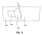
- Figure 3 depicts a FORMICA counter top containing the heater element.
- Figure 4 depicts a typical heater element embedded within a solid surface material.
- Figure 5 depicts a heater for a roof dam.
- Figure 6 depicts a typical inlaid concrete walkway containing a heater element.
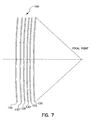
- Figure 7 depicts a cross section of an antenna dish showing the heater element of the invention.
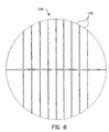
- Figure 8 depicts a front view of an antenna dish containing several heater elements of the invention.
- the present invention comprises a method for heating an antenna dish.
- the method comprises providing a heater element as defined in claim 1, disposing the heater element at a predetermined depth and location in the material and energizing the element at prescribed intervals and temperatures that are effective to heat the surface of the material.
- the heater element of the present invention is a laminated composite, impermeable to water, and is of the type disclosed in U.S. Patent No. 5,344,696 (Hastings et al.), which is incorporated herein by reference.
- the heater element comprises a durable outer ply that is resistant to abrasion and impermeable to water.
- the outer ply is bonded to and through a conductive layer of fibers and an integrally enveloping adhesive, which is adhered to the surface of a vessel.
- the conductive layer is connected to a source of electrical energy, and control means are adapted to control the temperature of the surface of the vessel.
- the heater element need not be a laminated structure. Rather, the heater element may comprise merely a layer of conductive fibers. This structure of the heater element is particularly useful if the material into which the heater element is embedded has dielectric properties that protect persons and property from electrical shock while evenly distributing the heat generated by the element.
- the preferred heater element is available under the trademark THERMION which is manufactured by Aerospace Safety Technologies, Inc.
- THERMION is light, flexible and may be translucent.
- This particular heater element is composed of a hybrid, nickel-coated, carbon fiber processed by current textile art into a thin, conductive, non-woven fabric.
- the material is a laminate that provides even heating and can be conformed to surfaces having a variety of different contours and shapes. Operational power can be derived from low or high voltage AC or DC power supplies.
- the heater element may comprise a layer of conductive fibers that are directly embedded into the material.
- the material must possess sufficient dielectric properties to protect persons and property from electrical shock and to distribute the heat generated by the fibers evenly to the surface of the material.
- Thermoplastic materials typically possess these properties.
- the heater element is disposed at a predetermined location and depth in the material.
- the depth and location may vary according to the particular material and type of heating required.
- the thin, unobtrusive nature of the heater element makes it suitable for use in ceramic and marble tile, solid surface materials, Formica, linoleum, and any other floor, wall, roof, or counter covering available.
- the following examples are not presented as embodiments of the present invention but serve as examples which are useful for understanding the present invention.
- a first example involves installing in the surface a pre-made panel, usually configured on a mold table for easy transfer to the final surface.
- the pre-made panel comprises a fiberglass resin encapsulated heater element 1, further encapsulated in two fiberglass/resin cloths 5 and 5'.
- the pre-made panel also contains electrical leads (not shown) attached to the heater element.
- the electrical leads extend outside of the panel and are attached to an electrical power supply.
- the laminate optionally can be constructed with multiple layers of the fiberglass resin encapsulated heater element 1.
- the multiple-layered heater element can provide greater control over the heat output from the assembly.
- Figure 1 shows how a single layer pre-made panel is formed on a transfer table.
- the fiberglass resin encapsulated heater element 1 is placed on top of a mold table surface 9.
- a mold release wax 15 is disposed between the encapsulated heater element 1 and the table surface 9.
- a peel ply 19 is placed above the encapsulated heater element 1.
- a release ply 21 is disposed above the peel ply 19 and a bleeder cloth 25 is disposed over the release ply 21.
- a vacuum bag 29 is disposed over the release ply 21.
- a seal tape 11 surrounding the layers on the mold is attached to the table top surface 9, and can adhere to the vacuum bag 29 to create a tight seal.
- a vacuum supply 33 is used to evacuate the air between the layered material in order to bring the layers into close contact with each other and cure the resin, bonding the layers to create the laminate.
- a pre-formed panel may be installed below a variety of covering surfaces, such as ceramic, marble, or similar paver tiles.
- the sub-base whether it is a floor or countertop, may first be covered by a particle board underlayment 100.
- a particle board underlayment 100 Some builders choose not to use an underlayment, but its purpose is to aid in leveling the floor and build uniformity.
- a vapor barrier and one or more concrete base products are then applied over the underlayment set.
- the concrete 102 should be at least 1/2 inch thick for standard wet/dry environments, such as kitchen and bathroom floors and counters (see Figures 2 and 3).
- the layer must be at least twice this thickness. Concrete serves a dual purpose.
- a heater element 104 is disposed above the concrete base 102.
- the heater element 104 optionally contains a syntactic film layer 106 on the back/bottom side for bonding the element 104 to the concrete base 102.
- Film layer 106 replaces the mastic that would otherwise be required to set heater element 104 in place. Without a bonding film layer, the installer would smear the concrete base with a thin layer of mastic, alternatively referred to as 105, apply the heater element from edge to edge, minimizing air pockets, and roll the element flat against the concrete base 102.
- the heater element 104 Once the heater element 104 is set, the normal process of installing tiles 101 can continue. If necessary, the panel may be punched with suitable tools to create holes or other shapes, as needed, and edge finished to protect against electrical shock. The holes, depending on their relative size and location, will have minimal to moderate effect on the heat output of the device.
- the heater element 104 can be installed under a countertop layer 108, such as a FORMICA or linoleum top layer, in a manner similar to tile, although the concrete base and vapor barrier are no longer required.
- FORMICA/linoleum installation generally utilizes contact adhesives which require additional processing known to those skilled in the art.
- a second example involves simultaneously constructing the composite heater element 104 at the time the floor, wall, roof, or countertop material is constructed.
- the composite in Figure 3 may be constructed on the sub-surface 109 simultaneously as the other layers of material are applied over the heater element 104.
- This is particularly useful in the construction of formica and metal countertops.
- This method is advantageous in that custom--shaped heater elements may be easily incorporated below the finished surface of the material.
- custom-shaped heater elements may be bonded under the finished surface of the material.
- the heater element is disposed on a solid, clean surface, and epoxy resin is applied to bond the element to the material.
- the composite may also be vacuum cured and heated, if desired.
- the vacuum process regulates the heater resin content in conjunction with the fiberglass selected.
- the top surface of the material may be finished, as desired.
- FORMICA a contact adhesive is applied between the element and the top surface before they are joined. Thereafter, the composite is rolled to complete the process.
- an example involves providing a heater element 104 without the fiberglass outer layers or resin and encapsulating the element 104 within the finished material at the factory/production level.
- Such an installation is suitable for solid surface 112 materials such as CORION or any other thermoplastic formed item that has sufficient dielectric strength to isolate the electric heater element from the surface, and that allows cohesive bonding through the heating element.
- Most structures developed by liquid process molding are excellent candidates.
- the placement of the heater element 104 can be accurately controlled providing heat as near to the surface as is practical and safe. Using standard counter depths, the heaters can be pre-formed to run front to back allowing the surface to be cut to length, and end finished. A front to back orientation refers to the direction of current flow.
- heater placement and orientation may be accomplished at the time of production, allowing for custom needs. Some circumstances may require surface heating in localized areas, for instance, the areas around a sink or other fixtures.
- the heater element may, therefore, be precut to any particular pattern and may contain holes or cuts, as is necessary.
- the surface could be cored within certain dimensions and edge finished, having minimal to moderate effect on the heater's performance.
- FIG. 5 shows a typical application of the heater element 104 to a roof.
- the typical roof heater comprises a wood sheeting substrate 109, felt paper 113, heater mastic 111, the heater element 104, and the finished roof layer 115.
- the finished roof layer 115 may be constructed of typical roof finish materials, such as neoprene rubber, metal, or the like.
- the heater element in a concrete walkway is depicted in Figure 6.
- the walkway contains a perforated panel 114, laid during construction over and above, or in place of, a remesh/rebar 116.
- the heater element 104 is perforated to allow cohesive bonding of the aggregated concrete 114 through the panel.
- a top layer of concrete is disposed above the element.
- the heater element may also be applied to rain gutters. Such application may be completed by use of any of the methods discussed. The particular method chosen depends on the installation and gutter product selected.
- the heater element may be applied to mirrors. Mirror application to prevent fogging is an example of a simple back side bonding.
- the heater may be a pre-formed panel or a formed-in-place installation. For radiant heat applications the methods are no different only the object selected to encase the material vary. Besides the possibility of heated pavers, diffused panels for a green house can incorporate the heated panels. The panels can be of simple or complex design and may provide winter environmental control and snow removal. Additional greenhouse installations could provide local heating as well for particular applications, such as lighting pairs for ice/snow protection and for heating/environmental control.
- the present invention concerns a method for heating the surface of an antenna dish to prevent and control the formation of ice on the surface of the dish.
- a heater element is incorporated into a composite that forms the surface of the antenna dish or the entire antenna dish.
- the heater element is composed of a layer of conductive fibers, preferably metal-coated fibers.
- the composite 150 is constructed by a process in which various materials, including the heater element, are layered over one another.
- the layers of the composite are cast in reverse order; the first layer cast in the process serves as the exterior surface of the final product.
- a gel coat layer 120 is cast or sprayed upon a support carrier or mold (not shown).
- the support carrier is removed and the gel coat 120 serves as the exterior finished surface of the antenna dish.
- the gel coat 120 protects the inner layers of the composite from the environment and also provides the surface of the dish with the necessary texture that enables the dish to function properly.
- a reflective fabric screen 125 is then disposed over the gel coat 120.
- the reflective screen 125 may serve as the transmitter or receiver of the antenna.
- a first layer 130' of resin and fiberglass "chop" (which consists of small strands of fiberglass) is then disposed over the reflective cloth 125 and allowed to set.
- the heater element 135 can be made of fabrics, such as THERMION, a man-made metal-coated fiber.
- Other fibers, such as natural metal-coated fibers, non-coated conductive fibers, metal-coated non-conductive fibers, and metal-coated conductive fibers are all possible candidates with suitable properties for most composite constructions.
- the conductive fiber material should possess certain characteristics so that the heater element can efficiently heat the surface of the dish.
- the conductive fiber material should be light weight, produce even heating, have a minimal thickness, and possess low thermal inertia.
- a conductive fiber material having low thermal inertia heats up and cools down quickly when the power is turned on and off, respectively. This quickness in heating and cooling facilitates greater control over the distribution of heat generated by the element.
- the conductive fiber material is approximately 6.7 grams per square meter (0.022 ounces per square foot) in weight and has a thickness of approximately 0.102 millimeter (0.004 inch).
- a second layer 130" of resin and fiberglass chop is disposed over the heater element 135 and is allowed to set.
- a backing substructure 145 is disposed over the second fiberglass resin layer 130".
- the substructure 145 may be constructed of balsa wood or other like materials.
- the fiberglass resin layers 130' and 130" provide structural support to the antenna dish and also electrically insulate the heater element 135 from the reflective fabric screen 125 so that they do not electrically interfere with each other or create a short circuit.
- one or two layers of resin and fiberglass chop should be positioned between the THERMION heater element 135 and the reflective cloth 125, depending on the conductive properties of the reflective cloth and the dielectric properties of the resin and fiberglass chop layer(s) 130'.
- the THERMION heater element is incorporated into the laminate and separated by the fiberglass resin layers 130' and 130" from the dish surface and from other conductive materials in the composite to prevent electric shock and short circuiting.
- Layers of fiberglass, or other fabrics having electrically-insulating properties are suitable dielectrics once encased in resin.
- Heaters can be configured in several different arrangements. Vertical panels, such as those shown in Figure 8, are preferable. In Figure 8, vertical panels 135 are disposed over approximately 75% of the surface area of the dish. The amount of the surface area covered by the vertical panels may be varied depending on the particular application.
- the heater elements embedded within vertical panels 135 can efficiently heat the entire surface of the dish.
- the heater element 135 is connected by wire and/or conductive ribbon to a suitable electric source (not shown), which provides the electrical power to heat the surface of the antenna dish.
- the power may be controlled by a simple on/off switch or by a more complex temperature/power controller that measures and monitors a number of parameters, including the atmospheric conditions in the vicinity of the antenna dish and the surface temperature of the dish.
- the controller also adjusts the power delivered to the heater element 135 to control the heat generated by the element in response to the surface temperature of the dish and the existing climate. Controllers that accomplish these tasks are known by those skilled in the art.
- Power requirements depend on the amount of heat needed, the size of the dish, and the available power supply. Wires and cables meet at a central controller housing near the dish and provide the necessary timing and temperature response signals to the source of electrical power.
Applications Claiming Priority (5)
| Application Number | Priority Date | Filing Date | Title |
|---|---|---|---|
| US633965 | 1996-04-19 | ||
| US08/633,965 US5932124A (en) | 1996-04-19 | 1996-04-19 | Method for heating a solid surface such as a floor, wall, or countertop surface |
| US08/701,607 US5942140A (en) | 1996-04-19 | 1996-08-22 | Method for heating the surface of an antenna dish |
| US701607 | 1996-08-22 | ||
| PCT/US1997/006435 WO1997040646A1 (en) | 1996-04-19 | 1997-04-18 | Method for heating the surface of an antenna dish |
Publications (2)
| Publication Number | Publication Date |
|---|---|
| EP0894417A1 EP0894417A1 (en) | 1999-02-03 |
| EP0894417B1 true EP0894417B1 (en) | 2000-12-27 |
Family
ID=27092022
Family Applications (1)
| Application Number | Title | Priority Date | Filing Date |
|---|---|---|---|
| EP97920428A Expired - Lifetime EP0894417B1 (en) | 1996-04-19 | 1997-04-18 | Method for heating the surface of an antenna dish |
Country Status (9)
| Country | Link |
|---|---|
| EP (1) | EP0894417B1 (da) |
| AT (1) | ATE198395T1 (da) |
| CA (1) | CA2252107C (da) |
| DE (1) | DE69703794T2 (da) |
| DK (1) | DK0894417T3 (da) |
| ES (1) | ES2154039T3 (da) |
| GR (1) | GR3035638T3 (da) |
| PT (1) | PT894417E (da) |
| WO (1) | WO1997040646A1 (da) |
Cited By (4)
| Publication number | Priority date | Publication date | Assignee | Title |
|---|---|---|---|---|
| US10841980B2 (en) | 2015-10-19 | 2020-11-17 | Laminaheat Holding Ltd. | Laminar heating elements with customized or non-uniform resistance and/or irregular shapes and processes for manufacture |
| US10925119B2 (en) | 2015-01-12 | 2021-02-16 | Laminaheat Holding Ltd. | Fabric heating element |
| USD911038S1 (en) | 2019-10-11 | 2021-02-23 | Laminaheat Holding Ltd. | Heating element sheet having perforations |
| EP4090132A1 (de) * | 2021-05-11 | 2022-11-16 | Steffen Lorenz | Elektrisch beheizbare betonplatte |
Families Citing this family (2)
| Publication number | Priority date | Publication date | Assignee | Title |
|---|---|---|---|---|
| DE202006005589U1 (de) * | 2006-04-04 | 2006-06-14 | Pfeiffer, Thomas | Beheizbares Flachdach |
| CN108583533A (zh) * | 2018-07-05 | 2018-09-28 | 无锡市人民医院 | 车辆自动除雪牌照架 |
Family Cites Families (6)
| Publication number | Priority date | Publication date | Assignee | Title |
|---|---|---|---|---|
| JPS5792777A (en) * | 1980-11-29 | 1982-06-09 | Sekisui Chemical Co Ltd | Method of producing panel heater |
| JPS6390204A (ja) * | 1986-09-30 | 1988-04-21 | レイケム・コーポレイション | 加熱された皿型アンテナ |
| DE8717554U1 (da) * | 1987-06-01 | 1989-02-16 | Man Technologie Gmbh, 8000 Muenchen, De | |
| DE9001255U1 (da) * | 1990-02-03 | 1990-04-05 | Hagenbusch, Guenther, 7313 Reichenbach, De | |
| IT1244904B (it) * | 1991-01-23 | 1994-09-13 | Selenia Spazio Spa Ora Alenia | Dispositivo di riscaldamento per antenne a base di fibre di carbonio, da utilizzare preferenzialmente per uso spaziale. |
| JPH05327341A (ja) * | 1992-05-27 | 1993-12-10 | Hitachi Home Tec Ltd | アンテナ反射体融雪装置 |
-
1997
- 1997-04-18 WO PCT/US1997/006435 patent/WO1997040646A1/en active IP Right Grant
- 1997-04-18 PT PT97920428T patent/PT894417E/pt unknown
- 1997-04-18 DK DK97920428T patent/DK0894417T3/da active
- 1997-04-18 EP EP97920428A patent/EP0894417B1/en not_active Expired - Lifetime
- 1997-04-18 DE DE69703794T patent/DE69703794T2/de not_active Expired - Fee Related
- 1997-04-18 AT AT97920428T patent/ATE198395T1/de not_active IP Right Cessation
- 1997-04-18 ES ES97920428T patent/ES2154039T3/es not_active Expired - Lifetime
- 1997-04-18 CA CA002252107A patent/CA2252107C/en not_active Expired - Fee Related
-
2001
- 2001-03-26 GR GR20010400483T patent/GR3035638T3/el not_active IP Right Cessation
Cited By (4)
| Publication number | Priority date | Publication date | Assignee | Title |
|---|---|---|---|---|
| US10925119B2 (en) | 2015-01-12 | 2021-02-16 | Laminaheat Holding Ltd. | Fabric heating element |
| US10841980B2 (en) | 2015-10-19 | 2020-11-17 | Laminaheat Holding Ltd. | Laminar heating elements with customized or non-uniform resistance and/or irregular shapes and processes for manufacture |
| USD911038S1 (en) | 2019-10-11 | 2021-02-23 | Laminaheat Holding Ltd. | Heating element sheet having perforations |
| EP4090132A1 (de) * | 2021-05-11 | 2022-11-16 | Steffen Lorenz | Elektrisch beheizbare betonplatte |
Also Published As
| Publication number | Publication date |
|---|---|
| DK0894417T3 (da) | 2001-03-26 |
| DE69703794D1 (de) | 2001-02-01 |
| GR3035638T3 (en) | 2001-06-29 |
| WO1997040646A1 (en) | 1997-10-30 |
| EP0894417A1 (en) | 1999-02-03 |
| PT894417E (pt) | 2001-05-31 |
| ATE198395T1 (de) | 2001-01-15 |
| DE69703794T2 (de) | 2001-08-09 |
| CA2252107A1 (en) | 1997-10-30 |
| ES2154039T3 (es) | 2001-03-16 |
| CA2252107C (en) | 2003-06-17 |
Similar Documents
| Publication | Publication Date | Title |
|---|---|---|
| US5942140A (en) | Method for heating the surface of an antenna dish | |
| US8618445B2 (en) | Heating system | |
| US7880121B2 (en) | Modular radiant heating apparatus | |
| CA2749318C (en) | Self-adhesive radiant heating underlayment | |
| US6188839B1 (en) | Radiant floor heating system with reflective layer and honeycomb panel | |
| EP2954753A2 (en) | Heating element | |
| US20080056694A1 (en) | Radiant heater | |
| WO2009055999A1 (fr) | Plaque chauffante électriquement conductrice et son procédé de fabrication et application | |
| CA2111216A1 (en) | Heated floor | |
| CN201203194Y (zh) | 电热复合地暖板 | |
| EP0894417B1 (en) | Method for heating the surface of an antenna dish | |
| CN117581634A (zh) | 石膏板类似物的建筑物面板辐射加热器 | |
| JPH0282485A (ja) | 平らなセラミック複合エレメント | |
| IT202100009305A1 (it) | Struttura di pannello radiante | |
| CN215723528U (zh) | 一种电地暖二次漏电防电击结构、电地暖及其铺设结构 | |
| US20210254840A1 (en) | Covering, functional element for a covering, and method for producing a covering | |
| RU2263253C2 (ru) | Электрообогреватель | |
| CN101690384A (zh) | 导电发热板及其制造方法和用途 | |
| CN105657876A (zh) | 自限温复合高分子碳晶电热装置及加热方法 | |
| CZ2055U1 (cs) | Elektrické podlahové topení |
Legal Events
| Date | Code | Title | Description |
|---|---|---|---|
| PUAI | Public reference made under article 153(3) epc to a published international application that has entered the european phase |
Free format text: ORIGINAL CODE: 0009012 |
|
| 17P | Request for examination filed |
Effective date: 19981026 |
|
| AK | Designated contracting states |
Kind code of ref document: A1 Designated state(s): AT BE CH DE DK ES FI FR GB GR IE IT LI LU MC NL PT SE |
|
| 17Q | First examination report despatched |
Effective date: 19990127 |
|
| GRAG | Despatch of communication of intention to grant |
Free format text: ORIGINAL CODE: EPIDOS AGRA |
|
| GRAG | Despatch of communication of intention to grant |
Free format text: ORIGINAL CODE: EPIDOS AGRA |
|
| GRAH | Despatch of communication of intention to grant a patent |
Free format text: ORIGINAL CODE: EPIDOS IGRA |
|
| GRAH | Despatch of communication of intention to grant a patent |
Free format text: ORIGINAL CODE: EPIDOS IGRA |
|
| GRAA | (expected) grant |
Free format text: ORIGINAL CODE: 0009210 |
|
| AK | Designated contracting states |
Kind code of ref document: B1 Designated state(s): AT BE CH DE DK ES FI FR GB GR IE IT LI LU MC NL PT SE |
|
| REF | Corresponds to: |
Ref document number: 198395 Country of ref document: AT Date of ref document: 20010115 Kind code of ref document: T |
|
| REG | Reference to a national code |
Ref country code: CH Ref legal event code: EP |
|
| REF | Corresponds to: |
Ref document number: 69703794 Country of ref document: DE Date of ref document: 20010201 |
|
| REG | Reference to a national code |
Ref country code: IE Ref legal event code: FG4D |
|
| REG | Reference to a national code |
Ref country code: CH Ref legal event code: NV Representative=s name: E. BLUM & CO. PATENTANWAELTE |
|
| REG | Reference to a national code |
Ref country code: ES Ref legal event code: FG2A Ref document number: 2154039 Country of ref document: ES Kind code of ref document: T3 |
|
| ITF | It: translation for a ep patent filed |
Owner name: PORTA CHECCACCI & ASSOCIATI S.P.A. |
|
| REG | Reference to a national code |
Ref country code: DK Ref legal event code: T3 |
|
| ET | Fr: translation filed | ||
| REG | Reference to a national code |
Ref country code: PT Ref legal event code: SC4A Free format text: AVAILABILITY OF NATIONAL TRANSLATION Effective date: 20010219 |
|
| PLBE | No opposition filed within time limit |
Free format text: ORIGINAL CODE: 0009261 |
|
| STAA | Information on the status of an ep patent application or granted ep patent |
Free format text: STATUS: NO OPPOSITION FILED WITHIN TIME LIMIT |
|
| 26N | No opposition filed | ||
| REG | Reference to a national code |
Ref country code: GB Ref legal event code: IF02 |
|
| PGFP | Annual fee paid to national office [announced via postgrant information from national office to epo] |
Ref country code: NL Payment date: 20020329 Year of fee payment: 6 |
|
| PGFP | Annual fee paid to national office [announced via postgrant information from national office to epo] |
Ref country code: SE Payment date: 20020403 Year of fee payment: 6 Ref country code: MC Payment date: 20020403 Year of fee payment: 6 Ref country code: DK Payment date: 20020403 Year of fee payment: 6 Ref country code: CH Payment date: 20020403 Year of fee payment: 6 Ref country code: AT Payment date: 20020403 Year of fee payment: 6 |
|
| PGFP | Annual fee paid to national office [announced via postgrant information from national office to epo] |
Ref country code: FI Payment date: 20020404 Year of fee payment: 6 |
|
| PGFP | Annual fee paid to national office [announced via postgrant information from national office to epo] |
Ref country code: PT Payment date: 20020408 Year of fee payment: 6 |
|
| PGFP | Annual fee paid to national office [announced via postgrant information from national office to epo] |
Ref country code: GR Payment date: 20020410 Year of fee payment: 6 |
|
| PGFP | Annual fee paid to national office [announced via postgrant information from national office to epo] |
Ref country code: LU Payment date: 20020415 Year of fee payment: 6 |
|
| PGFP | Annual fee paid to national office [announced via postgrant information from national office to epo] |
Ref country code: BE Payment date: 20020422 Year of fee payment: 6 |
|
| PGFP | Annual fee paid to national office [announced via postgrant information from national office to epo] |
Ref country code: IE Payment date: 20020429 Year of fee payment: 6 |
|
| PG25 | Lapsed in a contracting state [announced via postgrant information from national office to epo] |
Ref country code: LU Free format text: LAPSE BECAUSE OF NON-PAYMENT OF DUE FEES Effective date: 20030418 Ref country code: IE Free format text: LAPSE BECAUSE OF NON-PAYMENT OF DUE FEES Effective date: 20030418 Ref country code: FI Free format text: LAPSE BECAUSE OF NON-PAYMENT OF DUE FEES Effective date: 20030418 Ref country code: AT Free format text: LAPSE BECAUSE OF NON-PAYMENT OF DUE FEES Effective date: 20030418 |
|
| PG25 | Lapsed in a contracting state [announced via postgrant information from national office to epo] |
Ref country code: SE Free format text: LAPSE BECAUSE OF NON-PAYMENT OF DUE FEES Effective date: 20030419 |
|
| PG25 | Lapsed in a contracting state [announced via postgrant information from national office to epo] |
Ref country code: MC Free format text: LAPSE BECAUSE OF NON-PAYMENT OF DUE FEES Effective date: 20030430 Ref country code: LI Free format text: LAPSE BECAUSE OF NON-PAYMENT OF DUE FEES Effective date: 20030430 Ref country code: DK Free format text: LAPSE BECAUSE OF NON-PAYMENT OF DUE FEES Effective date: 20030430 Ref country code: CH Free format text: LAPSE BECAUSE OF NON-PAYMENT OF DUE FEES Effective date: 20030430 Ref country code: BE Free format text: LAPSE BECAUSE OF NON-PAYMENT OF DUE FEES Effective date: 20030430 |
|
| BERE | Be: lapsed |
Owner name: *THERMION SYSTEMS INTERNATIONAL Effective date: 20030430 |
|
| PG25 | Lapsed in a contracting state [announced via postgrant information from national office to epo] |
Ref country code: PT Free format text: LAPSE BECAUSE OF NON-PAYMENT OF DUE FEES Effective date: 20031031 |
|
| PG25 | Lapsed in a contracting state [announced via postgrant information from national office to epo] |
Ref country code: NL Free format text: LAPSE BECAUSE OF NON-PAYMENT OF DUE FEES Effective date: 20031101 |
|
| PG25 | Lapsed in a contracting state [announced via postgrant information from national office to epo] |
Ref country code: GR Free format text: LAPSE BECAUSE OF NON-PAYMENT OF DUE FEES Effective date: 20031104 |
|
| NLV4 | Nl: lapsed or anulled due to non-payment of the annual fee |
Effective date: 20031101 |
|
| EUG | Se: european patent has lapsed | ||
| REG | Reference to a national code |
Ref country code: DK Ref legal event code: EBP |
|
| REG | Reference to a national code |
Ref country code: CH Ref legal event code: PL |
|
| REG | Reference to a national code |
Ref country code: PT Ref legal event code: MM4A Free format text: LAPSE DUE TO NON-PAYMENT OF FEES Effective date: 20031031 |
|
| REG | Reference to a national code |
Ref country code: IE Ref legal event code: MM4A |
|
| PGFP | Annual fee paid to national office [announced via postgrant information from national office to epo] |
Ref country code: FR Payment date: 20060417 Year of fee payment: 10 |
|
| PGFP | Annual fee paid to national office [announced via postgrant information from national office to epo] |
Ref country code: GB Payment date: 20060424 Year of fee payment: 10 |
|
| PGFP | Annual fee paid to national office [announced via postgrant information from national office to epo] |
Ref country code: ES Payment date: 20060426 Year of fee payment: 10 |
|
| PGFP | Annual fee paid to national office [announced via postgrant information from national office to epo] |
Ref country code: IT Payment date: 20060430 Year of fee payment: 10 |
|
| PGFP | Annual fee paid to national office [announced via postgrant information from national office to epo] |
Ref country code: DE Payment date: 20060531 Year of fee payment: 10 |
|
| GBPC | Gb: european patent ceased through non-payment of renewal fee |
Effective date: 20070418 |
|
| PG25 | Lapsed in a contracting state [announced via postgrant information from national office to epo] |
Ref country code: DE Free format text: LAPSE BECAUSE OF NON-PAYMENT OF DUE FEES Effective date: 20071101 |
|
| PG25 | Lapsed in a contracting state [announced via postgrant information from national office to epo] |
Ref country code: GB Free format text: LAPSE BECAUSE OF NON-PAYMENT OF DUE FEES Effective date: 20070418 |
|
| REG | Reference to a national code |
Ref country code: ES Ref legal event code: FD2A Effective date: 20070419 |
|
| PG25 | Lapsed in a contracting state [announced via postgrant information from national office to epo] |
Ref country code: FR Free format text: LAPSE BECAUSE OF NON-PAYMENT OF DUE FEES Effective date: 20070430 |
|
| PG25 | Lapsed in a contracting state [announced via postgrant information from national office to epo] |
Ref country code: ES Free format text: LAPSE BECAUSE OF NON-PAYMENT OF DUE FEES Effective date: 20070419 |
|
| PG25 | Lapsed in a contracting state [announced via postgrant information from national office to epo] |
Ref country code: IT Free format text: LAPSE BECAUSE OF NON-PAYMENT OF DUE FEES Effective date: 20070418 |