EP0893598A2 - Fuel system - Google Patents
Fuel system Download PDFInfo
- Publication number
- EP0893598A2 EP0893598A2 EP98304730A EP98304730A EP0893598A2 EP 0893598 A2 EP0893598 A2 EP 0893598A2 EP 98304730 A EP98304730 A EP 98304730A EP 98304730 A EP98304730 A EP 98304730A EP 0893598 A2 EP0893598 A2 EP 0893598A2
- Authority
- EP
- European Patent Office
- Prior art keywords
- fuel
- pump
- throat
- line
- region
- Prior art date
- Legal status (The legal status is an assumption and is not a legal conclusion. Google has not performed a legal analysis and makes no representation as to the accuracy of the status listed.)
- Granted
Links
Images


Classifications
-
- F—MECHANICAL ENGINEERING; LIGHTING; HEATING; WEAPONS; BLASTING
- F02—COMBUSTION ENGINES; HOT-GAS OR COMBUSTION-PRODUCT ENGINE PLANTS
- F02M—SUPPLYING COMBUSTION ENGINES IN GENERAL WITH COMBUSTIBLE MIXTURES OR CONSTITUENTS THEREOF
- F02M63/00—Other fuel-injection apparatus having pertinent characteristics not provided for in groups F02M39/00 - F02M57/00 or F02M67/00; Details, component parts, or accessories of fuel-injection apparatus, not provided for in, or of interest apart from, the apparatus of groups F02M39/00 - F02M61/00 or F02M67/00; Combination of fuel pump with other devices, e.g. lubricating oil pump
- F02M63/02—Fuel-injection apparatus having several injectors fed by a common pumping element, or having several pumping elements feeding a common injector; Fuel-injection apparatus having provisions for cutting-out pumps, pumping elements, or injectors; Fuel-injection apparatus having provisions for variably interconnecting pumping elements and injectors alternatively
-
- F—MECHANICAL ENGINEERING; LIGHTING; HEATING; WEAPONS; BLASTING
- F02—COMBUSTION ENGINES; HOT-GAS OR COMBUSTION-PRODUCT ENGINE PLANTS
- F02M—SUPPLYING COMBUSTION ENGINES IN GENERAL WITH COMBUSTIBLE MIXTURES OR CONSTITUENTS THEREOF
- F02M37/00—Apparatus or systems for feeding liquid fuel from storage containers to carburettors or fuel-injection apparatus; Arrangements for purifying liquid fuel specially adapted for, or arranged on, internal-combustion engines
- F02M37/0047—Layout or arrangement of systems for feeding fuel
- F02M37/0052—Details on the fuel return circuit; Arrangement of pressure regulators
-
- F—MECHANICAL ENGINEERING; LIGHTING; HEATING; WEAPONS; BLASTING
- F02—COMBUSTION ENGINES; HOT-GAS OR COMBUSTION-PRODUCT ENGINE PLANTS
- F02M—SUPPLYING COMBUSTION ENGINES IN GENERAL WITH COMBUSTIBLE MIXTURES OR CONSTITUENTS THEREOF
- F02M55/00—Fuel-injection apparatus characterised by their fuel conduits or their venting means; Arrangements of conduits between fuel tank and pump F02M37/00
- F02M55/002—Arrangement of leakage or drain conduits in or from injectors
-
- F—MECHANICAL ENGINEERING; LIGHTING; HEATING; WEAPONS; BLASTING
- F04—POSITIVE - DISPLACEMENT MACHINES FOR LIQUIDS; PUMPS FOR LIQUIDS OR ELASTIC FLUIDS
- F04F—PUMPING OF FLUID BY DIRECT CONTACT OF ANOTHER FLUID OR BY USING INERTIA OF FLUID TO BE PUMPED; SIPHONS
- F04F5/00—Jet pumps, i.e. devices in which flow is induced by pressure drop caused by velocity of another fluid flow
- F04F5/44—Component parts, details, or accessories not provided for in, or of interest apart from, groups F04F5/02 - F04F5/42
- F04F5/46—Arrangements of nozzles
- F04F5/466—Arrangements of nozzles with a plurality of nozzles arranged in parallel
-
- F—MECHANICAL ENGINEERING; LIGHTING; HEATING; WEAPONS; BLASTING
- F02—COMBUSTION ENGINES; HOT-GAS OR COMBUSTION-PRODUCT ENGINE PLANTS
- F02M—SUPPLYING COMBUSTION ENGINES IN GENERAL WITH COMBUSTIBLE MIXTURES OR CONSTITUENTS THEREOF
- F02M59/00—Pumps specially adapted for fuel-injection and not provided for in groups F02M39/00 -F02M57/00, e.g. rotary cylinder-block type of pumps
- F02M59/38—Pumps characterised by adaptations to special uses or conditions
Definitions
- This invention relates to a fuel system for use in supplying fuel to the cylinders of a compression ignition internal combustion engine.
- this invention relates to a fuel system of the type comprising a high pressure fuel pump arranged to supply fuel to a plurality of injectors, and a backleak connection line whereby fuel from the injectors can be returned to a fuel reservoir.
- the fuel system may, for example, be of the common rail type.
- a fuel system of the type described hereinbefore further comprising a venturi pump connected to the backleak connection line and arranged to draw fuel from the backleak connection line to reduce the fuel pressure therein.
- venturi pump is conveniently located in a line connecting the backleak connection from the cam box of the high pressure fuel pump to the fuel reservoir.
- the venturi pump may be located in a return fuel line connecting the common rail to the fuel reservoir.
- the venturi pump may be connected to the inlet of the high pressure pump.
- the venturi pump is conveniently of the type comprising a throat member defining a flow passage including a throat region, and at least one feed port communicating with the throat region, wherein the part of the throat region immediately downstream of the feed port is of greater cross-sectional area than the part of the throat region immediately upstream of the feed port.
- the flow of fluid through the feed port does not result in a significant increase in the velocity of fluid flowing past the end of the feed port, thus a relatively large magnitude vacuum can still be drawn.
- the throat member conveniently takes the form of an insert intended to be received within a flow passage provided in a housing.
- the fuel system illustrated in Figure 1 comprises a fuel reservoir 10 which is connected through a filter 12 and low pressure fuel pump 14 with the inlet of a high pressure fuel pump 16. If desired, the low pressure pump may be located upstream of the filter.
- the high pressure fuel pump 16 is arranged to supply fuel under high pressure to a common rail 18 from which fuel is supplied under pressure to the inlets of a plurality of electromagnetically actuated injectors 20.
- the injectors 20 are operable under the control of an electronic controller 22 which is connected to the injectors 20 through control lines 24.
- the controller 22 is also connected through a control line 26 to the high pressure fuel pump 16 in order to control, for example, the rate at which fuel is being supplied to the common rail 18 by the high pressure fuel pump 16.
- the fuel pressure within the common rail 18 is sensed by a pressure sensor 28, the output of which is supplied to the controller 22 and is used to determine how much fuel should be supplied to the common rail 18 by the high pressure fuel pump 16.
- the common rail 18 communicates through a return line 30 with the fuel reservoir 10, a pressure limiting valve 32 being located in the return line 30 in order to maintain the fuel pressure within the common rail 18 at the desired working pressure.
- a backleak connection from the cam box of the high pressure fuel pump 16 is connected to a line 31 to return fuel to the fuel reservoir 10. This fuel is used, within the pump, to cool and lubricate the working parts within the pump cam box.
- a venturi pump 34 located within the line 31 is a venturi pump 34, the throat of which is connected to a backleak connection line 36 which is connected to the backleak connection port of each of the injectors 20.
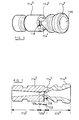
- FIG. 2 illustrates a venturi pump suitable for use in the fuel system of Figure 1.
- the venturi pump of Figure 2 comprises a body 38 having a blind bore 40 provided therein.
- the body 38 includes a head 42 of enlarged diameter, and the end of the body 38 remote from the head 42 is screw-threaded.
- An outlet connector 44 is secured to the body 38, the connector 44 being of annular form, the inner surface of the connector 44 including a groove which defines, with the body 38, an outlet chamber 46.
- the outlet chamber 46 communicates with the bore 40 through a radial passage 48 provided in the body 38.
- a drain line 50 is secured to the connector 44, communicating with the outlet chamber 46, the drain line 50 communicating with the fuel reservoir 10, in use.
- a backleak line connector 52 is located adjacent the connector 44, the backleak line connector 52 including an opening through which the body 38 extends, the body 38 and connector 52 defining a backleak chamber 54 which communicates with the bore 40 through a radial passage 56.
- the connector 52 includes a threaded bore 58 arranged to be connected, in use, to an end of the backleak connection line 36 to permit fuel from the backleak connection line 36 to flow to the backleak chamber 54.
- a return line connector (not shown) secured to the line 31 is secured, in use, to the threaded part of the body 38 to supply returned fuel to the bore 40.
- a sealing washer 60 is located between the connector 44 and the head 42, an O-ring 62 is located between the connector 44, the body 38 and the backleak line connector 52, and a sealing washer 64 is located between the backleak line connector 52 and return line connector. It will be appreciated that the return line connector secures the connector 44 and backleak line connector 52 in position, and applies a force of sufficient magnitude to the sealing washers 60, 64 and O-ring 62 to seal the connector 44 and backleak line connector 52 to the body 38.
- a throat member 66 is located within the bore 40 and is secured in position by the return line connector.
- the throat member 66 includes an axially extending passage 68 which includes a throat region of uniform, relatively small diameter adjacent the return line connector and a region which tapers to a maximum diameter at the end remote from the return line connector.
- the outer surface of the throat member 66 defines, with the bore 40, a chamber 70 which communicates with the passage 56. Drillings 72 are provided in the throat member 66 to provide communication between the chamber 70 and the throat region of the passage 68.
- fuel returned from the common rail high pressure pump flows through the passage 68, exiting the venturi pump through the outlet chamber 46 to be returned through the drain line 50 to the fuel reservoir.
- the shape of the passage 68 is such that the diameter of the throat region is smaller than that of the line 31, thus the velocity of fuel within the throat region is higher than that within the line 31.
- the increased velocity results in the fuel pressure within the throat region being reduced, drawing fuel from the chamber 70 through the drillings 72, thus reducing the fuel pressure within the backleak connection line 36.
- the reduced pressure within the backleak connection line 36 is advantageous in that it serves to maintain the fuel and gases within the backleak connection line 36 in the form of a foam which is capable of absorbing the pressure spikes or pulses which occur during injection which otherwise are detrimental to the operation of the other injectors connected to the backleak connection line 36.
- venturi pump is located in the line 31, it could be located elsewhere in the fuel system, for example at the inlet of the high pressure fuel pump in either a common rail system or in another type of fuel system, or in the return line 30 of the common rail system.
- Figure 3 illustrates a venturi pump arrangement which comprises a housing 110 defining a fluid flow passage 112.
- a throat member 114 is located within the passage 112, the throat member 114 including an axially extending through passage 116.
- the throat member 114 is shaped such that the passage 116 includes a first tapering region 116 a in which the diameter of the passage 116 tapers from a maximum at the upstream end of the throat member 114 to a minimum adjacent a throat region 116 b of the passage.
- the diameter of the passage 116 gradually increases in a second tapering region 116 c located downstream of the throat region 116 b .
- a plurality of ports 118 communicate with the throat region 116 b , the ports 118 communicating with an opening 120 which, in use, is connected to the backleak connection line 36 through which fuel is to be drawn.
- the first tapering region 116 a is constituted by an upstream frusto-conical region, a region of substantially uniform diameter, and a downstream frusto-conical region which is adjacent the upstream edge of the throat region 116 b .
- the throat region 116 b is constituted by a first, upstream end 122 of relatively small diameter, and a second, downstream end 124 which is of diameter greater than the diameter of the upstream end 122.
- the first and second ends 122, 124 of the throat region 116 b together define a step.
- each port 118 communicates with the through passage 116 defined by the throat member 114 at positions which straddle the step, thus part of each port 118 opens into the first, upstream end 122 of the throat region 116 b , each port 118 further including a part which opens into the second, downstream end 124 of the throat region 116 b .
- the downstream end 124 of the throat region 116 b opens into the second tapering region 116 c of the through passage 116 defined by the throat member 114.
- the opening 120 is connected to the backleak connection line 36 through which fuel is to be drawn.
- the flow passage 112 is connected to the line 31 such that fuel flows along the flow passage 112 and through the passage 116 defined by the throat member 114. It will be appreciated that the flow of fuel along the flow passage 112 is at relatively low velocity upstream of the throat member 114, the velocity of the fuel increasing as it flows through the first tapering region 116 a of the throat member 114. The velocity of the fuel flowing through the first, upstream end 122 of the throat region 116 b is significantly greater than that within the flow passage 112 upstream of the throat member 114, and as a result, the fuel pressure at the ends of the ports 118 is relatively low.
- the second, downstream end 124 of the throat region 116 b is of sufficiently large diameter relative to that of the first, upstream end 122 of the throat region 116 b that the increase in quantity of fuel flowing through this part of the throat region 116 b relative to the first, upstream end 122 thereof does not significantly increase the velocity of the fuel flowing through the throat region 116 b .
- a significant reduction in fluid pressure can still be achieved at the opening 120, and hence a relatively large magnitude vacuum can be drawn in the backleak connection line 36, even when fuel flows through the ports 118 at a significant rate.
- Figures 4 and 5 illustrate an arrangement containing two ports 118, each port 118 being defined by a recess formed in the outer periphery of the throat member, the recesses being shaped such that the parts thereof defining the ports 118 open into the throat region 116 b of the throat member 114 around the complete circumference of the part of the throat region 116 b at the intersection of the first end 122 and the second end 124 thereof.
- the throat member 114 illustrated in Figures 4 and 5 is designed to permit manufacture by injection moulding, and can be moulded as a single component using a reasonably small number of slides in the mould.
- the injection moulding process may be simplified further by manufacturing the throat member 114 in two separate pieces for example as illustrated in Figures 6 and 7 or in Figures 8 and 9.
- the throat member 114 is defined by a first, upstream component 114 a which defines the first tapering region 116 a and first, upstream end 122 of the throat region 116 b , and a second, downstream component 114 b which defines the second end 124 of the throat region 116 b and the second tapering region 116 c .
- the second component 114 b of the throat member 114 includes three projections 114 c which together serve to locate a frusto-conical end surface of the first component 114 a such that the combination of the first and second components 114 a , 114 b and the projections 114 c together define the ports 118 through which fuel is able to flow.
- ports 118 are located at the connection of the first and second components 114 a , 114 b , it will be appreciated that the ports 118 are aligned with the intersection between the first and second ends 122, 124 of the throat region 116 b .
- first and second components 114 a , 114 b of the throat member 114 are conveniently secured to one another by axial clamping, or by friction welding, achieved by rotating the first and second components 114 a , 114 b relative to one another, or by using an appropriate adhesive.
- Figures 8 and 9 illustrate an alternative arrangement in which the projections 114 c are omitted, and instead projections 114 d are provided on the first component 114 a of the throat member 114.
- the projections 114 d are arranged to be received within corresponding recesses or bores 114 e formed in the second component 114 b of the throat member 114.
- the projections 114 d serve to correctly locate the first and second components 114 a , 114 b of the throat member 114 with respect to one another, and to secure the components 114 a , 114 b to one another.
- the components 114 a , 114 b may simply be secured together by being a press fit, or alternatively may be welded by ultrasonic welding in which the first and second components 114 a , 114 b are vibrated axially with respect to one another.
- venturi pump is driven by fuel flowing through the line 31, it will be appreciated that it may be driven by other sources of fuel.
- the fuel used to drive the venturi pump may be derived from the output of the lift pump.
Abstract
Description
Claims (7)
- A fuel system comprising a high pressure fuel pump (16) arranged to supply fuel under pressure to a plurality of fuel injectors (20), a backleak connection line (36) whereby fuel from the injectors (20) can be returned to a fuel reservoir (10), and a venturi pump (34) connected to the backleak connection line (36) and arranged to draw fuel from the backleak connection line (36) to reduce the fuel pressure therein.
- A fuel system as claimed in Claim 1, wherein the venturi pump (34) is located in, and driven by the flow of fuel along, a line (31) connecting a backleak connection of a cam box of the high pressure fuel pump (16) and the fuel reservoir (10).
- A fuel system as claimed in Claim 1, wherein the venturi pump (34) is located in and driven by the flow of fuel along a line connected to an outlet of a transfer pump.
- A fuel system as claimed in Claim 1, wherein the venturi pump (34) is located in and driven by the flow of fuel along a line connected to an outlet of a lift pump.
- A fuel system as claimed in Claim 1, further comprising a common rail (18) from which fuel is supplied to the injectors (20), wherein the venturi pump is located in and driven by a flow of fuel along a line connecting the common rail (18) to the fuel reservoir (10).
- A fuel system as claimed in any one of the preceding claims, wherein the venturi pump (34) comprises a throat member (66, 114) defining a flow path (116) and including a throat region (116b) of dimensions causing fuel to flow at an increased velocity through the throat region (116b) relative to a part of the flow path upstream of the throat region (116b), at least one feed port (72, 118) communicating with the throat region (116b).
- A fuel system as claimed in Claim 6, wherein the throat region (116b) includes a downstream region of cross-sectional area greater than that of an upstream region, the feed port (118) being located at the intersection of the upstream and downstream regions.
Applications Claiming Priority (5)
| Application Number | Priority Date | Filing Date | Title |
|---|---|---|---|
| GB9715738 | 1997-07-26 | ||
| GBGB9715738.2A GB9715738D0 (en) | 1997-07-26 | 1997-07-26 | Fuel system |
| GB9811063 | 1998-05-23 | ||
| GBGB9811063.8A GB9811063D0 (en) | 1998-05-23 | 1998-05-23 | Venturi pump |
| US09/110,742 US5983869A (en) | 1997-07-26 | 1998-07-02 | Fuel system |
Publications (3)
| Publication Number | Publication Date |
|---|---|
| EP0893598A2 true EP0893598A2 (en) | 1999-01-27 |
| EP0893598A3 EP0893598A3 (en) | 2000-11-22 |
| EP0893598B1 EP0893598B1 (en) | 2003-05-28 |
Family
ID=27268951
Family Applications (1)
| Application Number | Title | Priority Date | Filing Date |
|---|---|---|---|
| EP98304730A Expired - Lifetime EP0893598B1 (en) | 1997-07-26 | 1998-06-16 | Fuel system |
Country Status (3)
| Country | Link |
|---|---|
| US (1) | US5983869A (en) |
| EP (1) | EP0893598B1 (en) |
| JP (1) | JP4152493B2 (en) |
Cited By (10)
| Publication number | Priority date | Publication date | Assignee | Title |
|---|---|---|---|---|
| EP1215390A1 (en) * | 2000-12-14 | 2002-06-19 | Filtrauto | Fuel feed device for an internal combustion engine and fuel filter for such a device |
| EP1039123A3 (en) * | 1999-03-24 | 2003-03-26 | Siemens Automotive Corporation | Fuel recirculation for direct injection fuel system using a high pressure variable venturi pump |
| EP1363016A2 (en) * | 2002-04-22 | 2003-11-19 | Delphi Technologies, Inc. | Fuel pump |
| WO2005038237A1 (en) * | 2003-09-19 | 2005-04-28 | Robert Bosch Gmbh | Fuel injection device for an internal combustion engine |
| EP1903209A1 (en) | 2004-11-25 | 2008-03-26 | ITT Manufacturing Enterprises, Inc. | Device to attach a fuel return line to a fuel injector and device to suction fuel from a fuel injector |
| EP2249021A1 (en) * | 2009-05-06 | 2010-11-10 | Delphi Technologies Holding S.à.r.l. | Fuel Delivery System |
| WO2014143261A1 (en) | 2013-03-15 | 2014-09-18 | United Technologies Corporation | Cartridge style ejector pump |
| GB2540549A (en) * | 2015-07-20 | 2017-01-25 | Delphi Int Operations Luxembourg Sarl | Novel fuel pump design |
| ITUA20162000A1 (en) * | 2016-03-24 | 2017-09-24 | Bosch Gmbh Robert | PUMPING GROUP FOR FUEL SUPPLEMENTATION, PREFERABLY GASOIL, TO AN INTERNAL COMBUSTION ENGINE |
| WO2018091488A1 (en) * | 2016-11-17 | 2018-05-24 | Delphi Technologies Ip Limited | High pressure fuel pump with venturi flow circuit |
Families Citing this family (18)
| Publication number | Priority date | Publication date | Assignee | Title |
|---|---|---|---|---|
| IT1306317B1 (en) * | 1998-07-16 | 2001-06-04 | Magneti Marelli Spa | HIGH PRESSURE PUMPING DEVICE |
| IT1306319B1 (en) * | 1998-07-16 | 2001-06-04 | Magneti Marelli Spa | GROUP OF FUEL SUPPLY TO AN ENDOTHERMAL ENGINE |
| DE19832842C1 (en) * | 1998-07-21 | 2000-02-17 | Bosch Gmbh Robert | Fuel delivery system for supplying fuel to an internal combustion engine |
| US6397826B1 (en) * | 1998-12-18 | 2002-06-04 | Clean Fuel Technology, Inc. | Fuel cooling system for fuel emulsion based compression ignition engine |
| GB9900070D0 (en) * | 1999-01-05 | 1999-02-24 | Lucas Franc | Control method |
| US6494190B1 (en) * | 2000-08-04 | 2002-12-17 | Siemens Automotive Corporation | Bi-fuel gasoline and low pressure gas fuel system and method of operation |
| US7195004B2 (en) * | 2002-09-25 | 2007-03-27 | Siemens Vdo Automotive Corporation | Fuel injector cup with improved lead-in dimensions for reduced insertion force |
| US7690361B2 (en) * | 2007-09-28 | 2010-04-06 | Cummins Inc. | System and method for metering fuel in a high pressure pump system |
| US20100170225A1 (en) * | 2009-01-08 | 2010-07-08 | Caterpillar Inc. | Exhaust treatment system having a reductant supply system |
| DE102009028023A1 (en) * | 2009-07-27 | 2011-02-03 | Robert Bosch Gmbh | High pressure injection system with fuel cooling from low pressure range |
| DE102010031700B4 (en) * | 2010-07-21 | 2013-12-05 | Continental Automotive Gmbh | Injection system for an internal combustion engine and fuel feed pump for this |
| DE102012204659A1 (en) * | 2012-03-22 | 2013-09-26 | Man Diesel & Turbo Se | Injector for a fuel supply system of an internal combustion engine and fuel supply system |
| TWM453728U (en) * | 2012-11-22 | 2013-05-21 | Shen S Glory Inc | Fuel supply device and oil reflow tee thereof |
| US10233072B2 (en) * | 2014-03-04 | 2019-03-19 | Benecor, Inc. | Diesel exhaust fluid systems |
| US10641406B2 (en) * | 2016-11-30 | 2020-05-05 | Universal Flow Monitors, Inc. | Venturi vacuum drawback assemblies and dual orifice venturi valve assemblies |
| US11555638B2 (en) * | 2016-11-30 | 2023-01-17 | Dwyer Instruments, Llc | Venturi vacuum drawback assemblies and dual orifice venturi valve assemblies |
| US11035483B2 (en) | 2018-02-07 | 2021-06-15 | Universal Flow Monitors, Inc. | Dual orifice venturi vacuum drawback assemblies having air breather check valve |
| US11092126B2 (en) * | 2019-09-03 | 2021-08-17 | Pratt & Whitney Canada Corp. | Common-rail fuel system with ejector pump and method of use thereof |
Family Cites Families (10)
| Publication number | Priority date | Publication date | Assignee | Title |
|---|---|---|---|---|
| DE3263992D1 (en) * | 1982-03-08 | 1985-07-11 | Deere & Co | Diesel engine cold starting arrangement |
| CH668621A5 (en) * | 1986-01-22 | 1989-01-13 | Dereco Dieselmotoren Forschung | FUEL INJECTION SYSTEM FOR AN INTERNAL COMBUSTION ENGINE. |
| DE3924127A1 (en) * | 1989-07-20 | 1991-01-31 | Bosch Gmbh Robert | FUEL INJECTION PUMP FOR INTERNAL COMBUSTION ENGINES |
| JP2596150B2 (en) * | 1989-12-13 | 1997-04-02 | 日産自動車株式会社 | Ejector pump for vehicle fuel tank |
| JPH05157015A (en) * | 1991-12-04 | 1993-06-22 | Nippondenso Co Ltd | Fuel device |
| DE4219516A1 (en) * | 1992-06-13 | 1993-12-16 | Bosch Gmbh Robert | Fuel tank with a container arranged in it |
| GB2268225B (en) * | 1992-06-29 | 1995-07-05 | Ford Motor Co | A fuel supply arrangement |
| DE4224981C2 (en) * | 1992-07-29 | 2003-06-26 | Bosch Gmbh Robert | Device for delivering fuel from a storage tank to the internal combustion engine of a motor vehicle |
| DE4333612C1 (en) * | 1993-10-01 | 1995-02-02 | Keld Gabelgaard | Suction method and devices for this |
| JP3296529B2 (en) * | 1995-02-14 | 2002-07-02 | 株式会社デンソー | Fuel injection device |
-
1998
- 1998-06-16 EP EP98304730A patent/EP0893598B1/en not_active Expired - Lifetime
- 1998-07-02 US US09/110,742 patent/US5983869A/en not_active Expired - Lifetime
- 1998-07-24 JP JP20985398A patent/JP4152493B2/en not_active Expired - Fee Related
Non-Patent Citations (1)
| Title |
|---|
| None |
Cited By (15)
| Publication number | Priority date | Publication date | Assignee | Title |
|---|---|---|---|---|
| EP1039123A3 (en) * | 1999-03-24 | 2003-03-26 | Siemens Automotive Corporation | Fuel recirculation for direct injection fuel system using a high pressure variable venturi pump |
| EP1215390A1 (en) * | 2000-12-14 | 2002-06-19 | Filtrauto | Fuel feed device for an internal combustion engine and fuel filter for such a device |
| FR2818322A1 (en) * | 2000-12-14 | 2002-06-21 | Filtrauto | FUEL SUPPLY DEVICE FOR AN INTERNAL COMBUSTION ENGINE AND FUEL FILTER FOR SUCH A DEVICE |
| EP1363016A2 (en) * | 2002-04-22 | 2003-11-19 | Delphi Technologies, Inc. | Fuel pump |
| EP1363016A3 (en) * | 2002-04-22 | 2005-02-09 | Delphi Technologies, Inc. | Fuel pump |
| US7219654B2 (en) | 2003-09-19 | 2007-05-22 | Robert Bosch Gmbh | Fuel injection device for an internal combustion engine |
| WO2005038237A1 (en) * | 2003-09-19 | 2005-04-28 | Robert Bosch Gmbh | Fuel injection device for an internal combustion engine |
| EP1903209A1 (en) | 2004-11-25 | 2008-03-26 | ITT Manufacturing Enterprises, Inc. | Device to attach a fuel return line to a fuel injector and device to suction fuel from a fuel injector |
| EP2249021A1 (en) * | 2009-05-06 | 2010-11-10 | Delphi Technologies Holding S.à.r.l. | Fuel Delivery System |
| WO2014143261A1 (en) | 2013-03-15 | 2014-09-18 | United Technologies Corporation | Cartridge style ejector pump |
| EP2971748A4 (en) * | 2013-03-15 | 2016-11-30 | United Technologies Corp | Cartridge style ejector pump |
| GB2540549A (en) * | 2015-07-20 | 2017-01-25 | Delphi Int Operations Luxembourg Sarl | Novel fuel pump design |
| WO2017012836A1 (en) * | 2015-07-20 | 2017-01-26 | Delphi International Operations Luxembourg S.À R.L. | Novel fuel pump design |
| ITUA20162000A1 (en) * | 2016-03-24 | 2017-09-24 | Bosch Gmbh Robert | PUMPING GROUP FOR FUEL SUPPLEMENTATION, PREFERABLY GASOIL, TO AN INTERNAL COMBUSTION ENGINE |
| WO2018091488A1 (en) * | 2016-11-17 | 2018-05-24 | Delphi Technologies Ip Limited | High pressure fuel pump with venturi flow circuit |
Also Published As
| Publication number | Publication date |
|---|---|
| US5983869A (en) | 1999-11-16 |
| JPH11107876A (en) | 1999-04-20 |
| EP0893598B1 (en) | 2003-05-28 |
| EP0893598A3 (en) | 2000-11-22 |
| JP4152493B2 (en) | 2008-09-17 |
Similar Documents
| Publication | Publication Date | Title |
|---|---|---|
| EP0893598B1 (en) | Fuel system | |
| JP2539635B2 (en) | Fuel injection system | |
| US5458292A (en) | Two-stage fuel injection nozzle | |
| US5002231A (en) | Injection valve | |
| US7780144B2 (en) | Valve, in particular for a high-pressure pump of a fuel injection system for an internal combustion engine | |
| US6684857B2 (en) | Common rail fuel injector for internal combustion engines, as well as a fuel system and an internal combustion engine incorporating the injector | |
| US4650122A (en) | Method for preparing fuel and injection valve for performing the method | |
| US6330876B1 (en) | High-pressure injection system with common rail | |
| JPS5934473A (en) | Feed conduit for fuel | |
| JP3370152B2 (en) | Fuel injection device for internal combustion period | |
| US20060008363A1 (en) | High-pressure pump, in particular for a fuel injection system of an internal combustion engine | |
| US7066148B2 (en) | Common rail having skew delivery ports | |
| US4258883A (en) | Fuel injection nozzle | |
| US5794856A (en) | Air assist injector and retainer shroud therefor | |
| US6536417B2 (en) | Easy flow improved edge filter and fuel system | |
| US5772123A (en) | Injector with solenoid-valve control for fuel injection into diesel internal-combustion engine combustion space | |
| US5755385A (en) | Fuel-injection valve for internal combustion engines | |
| EP0961022A2 (en) | Venturi pump | |
| US6145493A (en) | Fuel guidance system for a multicylinder internal combustion engine having inlet bores for connector pumps | |
| JP2722216B2 (en) | Piston cooling system | |
| KR100774342B1 (en) | Structure of liquefied petroleum injection fuel pump for vehicle | |
| US5355858A (en) | Assist-air type fuel injection method and device for internal combustion engine | |
| JP3882661B2 (en) | Fuel injection device | |
| JP2004116519A (en) | Fuel injector assembly | |
| GB2303404A (en) | I.c. engine fuel-injection valve with spill channel |
Legal Events
| Date | Code | Title | Description |
|---|---|---|---|
| PUAI | Public reference made under article 153(3) epc to a published international application that has entered the european phase |
Free format text: ORIGINAL CODE: 0009012 |
|
| AK | Designated contracting states |
Kind code of ref document: A2 Designated state(s): DE ES FR GB IT |
|
| AX | Request for extension of the european patent |
Free format text: AL;LT;LV;MK;RO;SI |
|
| RAP1 | Party data changed (applicant data changed or rights of an application transferred) |
Owner name: LUCAS INDUSTRIES LIMITED |
|
| PUAL | Search report despatched |
Free format text: ORIGINAL CODE: 0009013 |
|
| RIC1 | Information provided on ipc code assigned before grant |
Free format text: 7F 02M 55/00 A, 7F 02M 63/02 B, 7F 04F 5/46 B |
|
| AK | Designated contracting states |
Kind code of ref document: A3 Designated state(s): AT BE CH CY DE DK ES FI FR GB GR IE IT LI LU MC NL PT SE |
|
| AX | Request for extension of the european patent |
Free format text: AL;LT;LV;MK;RO;SI |
|
| RAP1 | Party data changed (applicant data changed or rights of an application transferred) |
Owner name: DELPHI TECHNOLOGIES, INC. |
|
| 17P | Request for examination filed |
Effective date: 20010510 |
|
| AKX | Designation fees paid |
Free format text: DE ES FR GB IT |
|
| 17Q | First examination report despatched |
Effective date: 20020325 |
|
| GRAH | Despatch of communication of intention to grant a patent |
Free format text: ORIGINAL CODE: EPIDOS IGRA |
|
| GRAH | Despatch of communication of intention to grant a patent |
Free format text: ORIGINAL CODE: EPIDOS IGRA |
|
| GRAA | (expected) grant |
Free format text: ORIGINAL CODE: 0009210 |
|
| AK | Designated contracting states |
Designated state(s): DE ES FR GB IT |
|
| PG25 | Lapsed in a contracting state [announced via postgrant information from national office to epo] |
Ref country code: IT Free format text: LAPSE BECAUSE OF FAILURE TO SUBMIT A TRANSLATION OF THE DESCRIPTION OR TO PAY THE FEE WITHIN THE PRESCRIBED TIME-LIMIT;WARNING: LAPSES OF ITALIAN PATENTS WITH EFFECTIVE DATE BEFORE 2007 MAY HAVE OCCURRED AT ANY TIME BEFORE 2007. THE CORRECT EFFECTIVE DATE MAY BE DIFFERENT FROM THE ONE RECORDED. Effective date: 20030528 |
|
| REG | Reference to a national code |
Ref country code: GB Ref legal event code: FG4D |
|
| PGFP | Annual fee paid to national office [announced via postgrant information from national office to epo] |
Ref country code: ES Payment date: 20030624 Year of fee payment: 6 |
|
| REF | Corresponds to: |
Ref document number: 69814992 Country of ref document: DE Date of ref document: 20030703 Kind code of ref document: P |
|
| PG25 | Lapsed in a contracting state [announced via postgrant information from national office to epo] |
Ref country code: GB Free format text: LAPSE BECAUSE OF NON-PAYMENT OF DUE FEES Effective date: 20030828 |
|
| PG25 | Lapsed in a contracting state [announced via postgrant information from national office to epo] |
Ref country code: ES Free format text: LAPSE BECAUSE OF FAILURE TO SUBMIT A TRANSLATION OF THE DESCRIPTION OR TO PAY THE FEE WITHIN THE PRESCRIBED TIME-LIMIT Effective date: 20030908 |
|
| ET | Fr: translation filed | ||
| PLBE | No opposition filed within time limit |
Free format text: ORIGINAL CODE: 0009261 |
|
| STAA | Information on the status of an ep patent application or granted ep patent |
Free format text: STATUS: NO OPPOSITION FILED WITHIN TIME LIMIT |
|
| GBPC | Gb: european patent ceased through non-payment of renewal fee | ||
| 26N | No opposition filed |
Effective date: 20040302 |
|
| REG | Reference to a national code |
Ref country code: FR Ref legal event code: TP |
|
| REG | Reference to a national code |
Ref country code: FR Ref legal event code: TP Owner name: DELPHI INTERNATIONAL OPERATIONS LUXEMBOURG S.A, LU Effective date: 20140516 |
|
| REG | Reference to a national code |
Ref country code: DE Ref legal event code: R082 Ref document number: 69814992 Country of ref document: DE Representative=s name: MANITZ, FINSTERWALD & PARTNER GBR, DE |
|
| REG | Reference to a national code |
Ref country code: DE Ref legal event code: R082 Ref document number: 69814992 Country of ref document: DE Representative=s name: MANITZ, FINSTERWALD & PARTNER GBR, DE Effective date: 20140702 Ref country code: DE Ref legal event code: R081 Ref document number: 69814992 Country of ref document: DE Owner name: DELPHI INTERNATIONAL OPERATIONS LUXEMBOURG S.A, LU Free format text: FORMER OWNER: DELPHI TECHNOLOGIES HOLDING S.A.R.L., BASCHARAGE, LU Effective date: 20140702 |
|
| PGFP | Annual fee paid to national office [announced via postgrant information from national office to epo] |
Ref country code: DE Payment date: 20140627 Year of fee payment: 17 |
|
| PGFP | Annual fee paid to national office [announced via postgrant information from national office to epo] |
Ref country code: FR Payment date: 20140617 Year of fee payment: 17 |
|
| REG | Reference to a national code |
Ref country code: DE Ref legal event code: R119 Ref document number: 69814992 Country of ref document: DE |
|
| REG | Reference to a national code |
Ref country code: FR Ref legal event code: ST Effective date: 20160229 |
|
| PG25 | Lapsed in a contracting state [announced via postgrant information from national office to epo] |
Ref country code: DE Free format text: LAPSE BECAUSE OF NON-PAYMENT OF DUE FEES Effective date: 20160101 |
|
| PG25 | Lapsed in a contracting state [announced via postgrant information from national office to epo] |
Ref country code: FR Free format text: LAPSE BECAUSE OF NON-PAYMENT OF DUE FEES Effective date: 20150630 |