EP0893376B1 - Scraper blade for primary belt scraper - Google Patents
Scraper blade for primary belt scraper Download PDFInfo
- Publication number
- EP0893376B1 EP0893376B1 EP98305483A EP98305483A EP0893376B1 EP 0893376 B1 EP0893376 B1 EP 0893376B1 EP 98305483 A EP98305483 A EP 98305483A EP 98305483 A EP98305483 A EP 98305483A EP 0893376 B1 EP0893376 B1 EP 0893376B1
- Authority
- EP
- European Patent Office
- Prior art keywords
- scraper blade
- support
- scraper
- blade
- blade according
- Prior art date
- Legal status (The legal status is an assumption and is not a legal conclusion. Google has not performed a legal analysis and makes no representation as to the accuracy of the status listed.)
- Expired - Fee Related
Links
Images

Classifications
-
- B—PERFORMING OPERATIONS; TRANSPORTING
- B65—CONVEYING; PACKING; STORING; HANDLING THIN OR FILAMENTARY MATERIAL
- B65G—TRANSPORT OR STORAGE DEVICES, e.g. CONVEYORS FOR LOADING OR TIPPING, SHOP CONVEYOR SYSTEMS OR PNEUMATIC TUBE CONVEYORS
- B65G45/00—Lubricating, cleaning, or clearing devices
- B65G45/10—Cleaning devices
- B65G45/12—Cleaning devices comprising scrapers
Definitions
- This invention relates to a primary belt scraper.
- a scraper of this type may be used alone or in conjunction with one or more so-called secondary scrapers wherever a dual cleaning system is required.
- the primary scraper is mounted on a head pulley of a conveyor belt and removes the bulk of the material which adheres to the belt. By careful design of the blades of a primary scraper it is possible to compensate for blade wear to a substantial extent.
- EP-A-573688 describes a conveyor belt precleaner in which a doctor blade is supported on a flexible mount. The doctor blade is attached to the mount by one or more tenon and mortise connectors.
- the invention provides a composite scraper as set forth in claim 1.
- the first material may be more rigid than the second material.
- the first material may be less expensive than the second material.
- the second material may be a second plastics material.
- the first material is nylon or polyamide and the second material is polyurethane.
- the support may be formed with keying formations to ensure a firm bond between the support and the scraping element.
- the support may be shaped with ribs and hollows to save material and to enhance the rigidity of the support.
- the support may include a base section and a curved section and the curved section may be embedded in the material of the scraping element.
- the support includes a lower section in which is formed at least one aperture and clip formation at the aperture.
- the invention also provides a scraper blade assembly which includes a mounting beam, a retaining pin on the beam, and a support of the aforementioned kind, the pin being located in the aperture and the clip formation being engaged with the retaining pin.
- the invention further extends to a method of mounting the scraper blade to a support beam which includes the steps of positioning a portion of the blade between opposing members of support structure attached to the beam, moving the scraper blade so that a retaining pin of the support structure is located inside an aperture formed in the scraper blade, and allowing a clip formation in the scraper blade to engage with a catch formation in the pin thereby to secure the blade to the support beam.
- FIGS 1 to 3 of the accompanying drawings illustrate a composite scraper blade 10 according to the invention which is particularly suited for use with a primary belt scraper although its use is not limited in any way.
- the manner in which a primary belt scraper is employed is known in the art and consequently is not further described herein.
- the blade 10 includes a support 12 which is moulded from a suitable plastics material such as polyamide, and a scraping element 14 which is formed from a suitable polyurethane formulation.
- the support 12 has a base section 16 which is formed with a plurality of ribs 18 and recesses 20 in order to impart to the support sufficient strength and rigidity while at the same time conserving material. Holes 22 and 24 extend through the base section 16.
- the support 12 has a curved upper insert section 26. As is evident particularly from Figure 2 the section 26 has a plurality of ribs 28 and grooves 30 over its surface.
- the support 12 is preformed in a moulding process.
- the scraping element 14 is thereafter engaged with the support by locating the curved section 26 in a suitable mould and introducing polyurethane into the mould.
- the polyurethane bonds directly to the rib and groove surfaces of the insert section 26, which act as keying formations.
- the element 14 has a shape and size which are determined by the scraping action required of the blade 10.
- the blade 10 is mounted to a suitable support, not shown, by means of bolts which engage with the holes 22 and 24.
- the scraping element 14 has a leading scraping edge 32 which is brought into scraping contact with a conveyor belt at the head pulley of a conveyor installation.
- the blade 10, in use, is abraded and the element 14 is worn away from the edge 32 towards the insert section 26.
- the wear which takes place in the blade 10 is compensated for either automatically or by means of periodic manual adjustments of the blade relatively to the conveyor belt.
- a leading end 34 of the insert section is also abraded.
- This is acceptable for the support 12 is made from a material such as polyamide which can abrade.
- the scraping action which can be obtained from polyamide is however not as good as the scraping action which is obtained from polyurethane.
- the benefit of the invention lies in the composite construction provided by the support 12 and the element 14 which are made from different materials with different properties.
- the bulk of the scraping action is achieved by means of the element 14 and, for this reason, the element is formed from a suitable material such as polyurethane.
- the polyurethane is abrasion resistant and has an inherent flexibility which allows it to deflect to accommodate irregularities in the belt surface which is being cleaned.
- the polyurethane is however more expensive than the polyamide from which the support 12 is formed.
- the polyamide is more rigid than the polyurethane and acts as a stiffening insert for the scraping element 14, providing a sound supporting structure at relatively lower cost.
- the more expensive polyurethane which has desirable scraping properties is principally employed during the scraping lifetime of the blade.
- the curved shape of the insert enables the polyurethane to be shaped in a corresponding manner and so present a defined scraping surface to the belt.
- Figures 4 and 5 illustrate from the side and front respectively the combination of a modified support 12A, and the manner in which the support is mounted to a support beam 40.
- the lower end of the support 12A is formed with a section 42, which is similar to the section 12 shown in Figures 1 and 2, but wherein the holes 22 and 24 are altered in shape and size, as required, to form respective apertures 44, although only one aperture is shown in Figures 4 and 5.
- the aperture 44 has a rounded upper end 46, see Figure 5, and a clip formation 48 at its lower end.
- a backing plate 50 extends from extends from its base 51, to the beam 40 and a transversely extending retaining pin 52 extends laterally from the plate 50.
- the pin has a slot or catch formation 54 in its lower surface.
- the components may be welded to each other, as required, or any other suitable form of construction may be employed.
- a stop plate 56 is located on one side of the beam 40.
- the support 12A is secured to the beam 40 by positioning the base 58 of the section 42 on the beam between the base 51 of the plate 50 and an opposing surface of the stop plate.
- the section 42 is then moved with a pivotal action, in the direction of an arrow 60, so that the retaining pin 52 enters the aperture 44.
- the section is pushed towards the plate 50 the leading end of the pin forces the clip formation 48 downwardly, in the direction of an arrow 62.
- the clip formation enters the slot 54 and secures the support 12A to the beam 40.
- the scraper blade may be fixed to the beam 40 without making use of tools.
- a screwdriver or similar sharp implement is used to lever the clip formation downwardly, in the direction of the arrow 62, so that it disengages from the slot 54.
- the scraper blade may then be detached from the beam 40.
- the mounting arrangement therefore holds considerable benefits in that it facilitates installation and maintenance of a scraper assembly.
Description
- This invention relates to a primary belt scraper.
- A scraper of this type may be used alone or in conjunction with one or more so-called secondary scrapers wherever a dual cleaning system is required. The primary scraper is mounted on a head pulley of a conveyor belt and removes the bulk of the material which adheres to the belt. By careful design of the blades of a primary scraper it is possible to compensate for blade wear to a substantial extent.
- Use has been made of polyurethane for primary scraper blades. This material is satisfactory in many respects but is fairly expensive, an aspect which is compounded by the fact that an entire blade is discarded when the scraping portion has become worn.
- EP-A-573688 describes a conveyor belt precleaner in which a doctor blade is supported on a flexible mount. The doctor blade is attached to the mount by one or more tenon and mortise connectors.
- Yet another conveyor belt precleaner is known from US 5 197 587.
- The invention provides a composite scraper as set forth in
claim 1. - The first material may be more rigid than the second material.
- The first material may be less expensive than the second material.
- The second material may be a second plastics material.
- In one embodiment of the invention the first material is nylon or polyamide and the second material is polyurethane.
- The support may be formed with keying formations to ensure a firm bond between the support and the scraping element.
- The support may be shaped with ribs and hollows to save material and to enhance the rigidity of the support.
- The support may include a base section and a curved section and the curved section may be embedded in the material of the scraping element.
- In a variation of the invention the support includes a lower section in which is formed at least one aperture and clip formation at the aperture.
- The invention also provides a scraper blade assembly which includes a mounting beam, a retaining pin on the beam, and a support of the aforementioned kind, the pin being located in the aperture and the clip formation being engaged with the retaining pin.
- The invention further extends to a method of mounting the scraper blade to a support beam which includes the steps of positioning a portion of the blade between opposing members of support structure attached to the beam, moving the scraper blade so that a retaining pin of the support structure is located inside an aperture formed in the scraper blade, and allowing a clip formation in the scraper blade to engage with a catch formation in the pin thereby to secure the blade to the support beam.
- The invention is further described by way of examples with reference to the accompanying drawings in which:
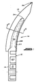
- Figure 1 is a side view, partly sectioned, of a composite scraper blade according to the invention,
- Figure 2 is a cross-sectional view of the blade of Figure 1 taken on the line 2-2,
- Figure 3 is an end view of a base portion of the scraper blade shown in Figure 1,
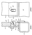
- Figure 4 is a cross-sectional side view of a lower end of a scraper blade, mounted to a support beam, according to a variation of the invention, and
- Figure 5 is a front view of the arrangement shown in Figure 4.
-
- Figures 1 to 3 of the accompanying drawings illustrate a
composite scraper blade 10 according to the invention which is particularly suited for use with a primary belt scraper although its use is not limited in any way. The manner in which a primary belt scraper is employed is known in the art and consequently is not further described herein. - The
blade 10 includes asupport 12 which is moulded from a suitable plastics material such as polyamide, and ascraping element 14 which is formed from a suitable polyurethane formulation. - The
support 12 has a base section 16 which is formed with a plurality ofribs 18 and recesses 20 in order to impart to the support sufficient strength and rigidity while at the same time conserving material.Holes 22 and 24 extend through the base section 16. - The
support 12 has a curvedupper insert section 26. As is evident particularly from Figure 2 thesection 26 has a plurality ofribs 28 and grooves 30 over its surface. - The
support 12 is preformed in a moulding process. Thescraping element 14 is thereafter engaged with the support by locating thecurved section 26 in a suitable mould and introducing polyurethane into the mould. The polyurethane bonds directly to the rib and groove surfaces of theinsert section 26, which act as keying formations. - The
element 14 has a shape and size which are determined by the scraping action required of theblade 10. - The
blade 10 is mounted to a suitable support, not shown, by means of bolts which engage with theholes 22 and 24. Thescraping element 14 has a leadingscraping edge 32 which is brought into scraping contact with a conveyor belt at the head pulley of a conveyor installation. Theblade 10, in use, is abraded and theelement 14 is worn away from theedge 32 towards theinsert section 26. The wear which takes place in theblade 10 is compensated for either automatically or by means of periodic manual adjustments of the blade relatively to the conveyor belt. - Ultimately a point is reached at which a leading
end 34 of the insert section is also abraded. This is acceptable for thesupport 12 is made from a material such as polyamide which can abrade. The scraping action which can be obtained from polyamide is however not as good as the scraping action which is obtained from polyurethane. - Once the
blade 10 has worn beyond a limiting state the blade is discarded and replaced with a fresh blade. - The benefit of the invention lies in the composite construction provided by the
support 12 and theelement 14 which are made from different materials with different properties. The bulk of the scraping action is achieved by means of theelement 14 and, for this reason, the element is formed from a suitable material such as polyurethane. The polyurethane is abrasion resistant and has an inherent flexibility which allows it to deflect to accommodate irregularities in the belt surface which is being cleaned. The polyurethane is however more expensive than the polyamide from which thesupport 12 is formed. The polyamide is more rigid than the polyurethane and acts as a stiffening insert for thescraping element 14, providing a sound supporting structure at relatively lower cost. Thus when theblade 10 is ultimately discarded the relatively inexpensive material forms the bulk of the discarded blade. Conversely, as has been pointed out, the more expensive polyurethane which has desirable scraping properties is principally employed during the scraping lifetime of the blade. - It is apparent as well that the shape and size of the
blade 10 can be altered according to requirement. The curved shape of the insert enables the polyurethane to be shaped in a corresponding manner and so present a defined scraping surface to the belt. - Figures 4 and 5 illustrate from the side and front respectively the combination of a modified
support 12A, and the manner in which the support is mounted to asupport beam 40. - The lower end of the
support 12A is formed with asection 42, which is similar to thesection 12 shown in Figures 1 and 2, but wherein theholes 22 and 24 are altered in shape and size, as required, to form respective apertures 44, although only one aperture is shown in Figures 4 and 5. The aperture 44 has a rounded upper end 46, see Figure 5, and aclip formation 48 at its lower end. A backing plate 50 extends from extends from its base 51, to thebeam 40 and a transversely extendingretaining pin 52 extends laterally from the plate 50. The pin has a slot orcatch formation 54 in its lower surface. The components may be welded to each other, as required, or any other suitable form of construction may be employed. - A
stop plate 56 is located on one side of thebeam 40. Thesupport 12A is secured to thebeam 40 by positioning thebase 58 of thesection 42 on the beam between the base 51 of the plate 50 and an opposing surface of the stop plate. Thesection 42 is then moved with a pivotal action, in the direction of an arrow 60, so that the retainingpin 52 enters the aperture 44. As the section is pushed towards the plate 50 the leading end of the pin forces theclip formation 48 downwardly, in the direction of anarrow 62. When the section reaches the position shown in Figure 4 the clip formation enters theslot 54 and secures thesupport 12A to thebeam 40. Thus the scraper blade may be fixed to thebeam 40 without making use of tools. - In order to remove the blade a screwdriver or similar sharp implement is used to lever the clip formation downwardly, in the direction of the
arrow 62, so that it disengages from theslot 54. The scraper blade may then be detached from thebeam 40. The mounting arrangement therefore holds considerable benefits in that it facilitates installation and maintenance of a scraper assembly.
Claims (9)
- A composite scraper blade (10) which is suitable for use with a primary belt scraper which includes a support (12) formed from a first plastics material and which is characterised in that an abrasion resistant scraping element (14) which is formed from a second material is moulded onto, and bonded to, the support and at least partially encases the support.
- A scraper blade according to claim 1 wherein the second material is a second plastics material.
- A scraper blade according to claim 1 or 2 wherein the first material is nylon or polyamide.
- A scraper blade according to claim 1, 2 or 3 wherein the second material is polyurethane.
- A scraper blade according to any one of claims 1 to 4 wherein the support (12) includes a base section (16) and a curved section (26) and the curved section is engaged with the scraping element- (14).
- A scraper blade according to claim 5 wherein the base section (16) includes formations for direct attachment to support structure.
- A scraper blade according to any one of claims 1 to 6 wherein the support (12) includes a lower section in which is formed at least one aperture and a resilient clip formation (48) at the aperture.
- A scraper blade assembly which includes a mounting beam (40), a retaining pin (52) on the beam, and a scraper blade according to claim 7, wherein the pin is located in the aperture and the clip formation (48) is engaged with the retaining pin.
- A method of mounting a scraper blade to a support beam which is characterised by the steps of positioning a portion of the blade (42) between opposing members (50, 56) of support structure attached to the beam (40), moving the scraper blade so that a retaining pin (52) of the support structure is located inside an aperture (44) formed in the scraper blade, and allowing a resilient clip formation (48) on the scraper blade to engage with a catch formation (54) on the pin thereby to secure the blade to the support beam, and further characterised in that the scraper blade is a blade according to any one of claims 1 to 7.
Applications Claiming Priority (2)
| Application Number | Priority Date | Filing Date | Title |
|---|---|---|---|
| ZA976409 | 1997-07-21 | ||
| ZA9706409 | 1997-07-21 |
Publications (2)
| Publication Number | Publication Date |
|---|---|
| EP0893376A1 EP0893376A1 (en) | 1999-01-27 |
| EP0893376B1 true EP0893376B1 (en) | 2001-11-07 |
Family
ID=25586486
Family Applications (1)
| Application Number | Title | Priority Date | Filing Date |
|---|---|---|---|
| EP98305483A Expired - Fee Related EP0893376B1 (en) | 1997-07-21 | 1998-07-10 | Scraper blade for primary belt scraper |
Country Status (6)
| Country | Link |
|---|---|
| US (1) | US5944167A (en) |
| EP (1) | EP0893376B1 (en) |
| CN (1) | CN1209368A (en) |
| AU (1) | AU742958B2 (en) |
| DE (1) | DE69802349T2 (en) |
| ES (1) | ES2168150T3 (en) |
Families Citing this family (23)
| Publication number | Priority date | Publication date | Assignee | Title |
|---|---|---|---|---|
| AU738112B2 (en) * | 1997-07-25 | 2001-09-06 | Scorpio Conveyor Products (Proprietary) Limited | Conveyor scraper and mounting of scraper blade |
| US6082524A (en) * | 1998-07-02 | 2000-07-04 | Slic Trading Company Limited | Composite scraper blade |
| US6374991B1 (en) * | 1999-03-19 | 2002-04-23 | Martin Engineering Company | Conveyor belt cleaner and tensioner assembly |
| US6349816B1 (en) * | 1999-04-15 | 2002-02-26 | Martin Engineering Company | Fluted conveyor belt cleaner scraper blade |
| US6315105B1 (en) * | 1999-06-22 | 2001-11-13 | Asgco Manufacturing, Inc. | Conveyor belt scraping apparatus |
| US6296105B1 (en) * | 1999-12-21 | 2001-10-02 | Shaun K. Carnes | Belt scraper |
| US6457575B2 (en) * | 2000-06-26 | 2002-10-01 | Martin Engineering Company | Self-locking pin mounting arrangement for conveyor belt cleaner scraper blades |
| SE0103292L (en) | 2001-10-03 | 2003-02-04 | Metso Minerals Trelleborg Ab | Scraper blade, especially conveyor belt scraper |
| US6926133B2 (en) * | 2003-03-27 | 2005-08-09 | Flexible Steel Lacing Company | Scraper blade for conveyor belts |
| FR2854149B1 (en) | 2003-04-22 | 2005-06-10 | Financ De Gestion Soc | SCRAP BLADE |
| US6968940B2 (en) * | 2003-12-16 | 2005-11-29 | Argonics, Inc. | Universal mount for a cleaning blade for a conveying belt |
| FI116797B (en) * | 2004-03-25 | 2006-02-28 | Runtech Systems Oy | spring Scraper |
| JP4012208B2 (en) * | 2005-04-12 | 2007-11-21 | 日本通商株式会社 | Belt cleaner device |
| SE529368C2 (en) * | 2005-10-07 | 2007-07-17 | Metso Minerals Wear Prot Ab | Scraper blades and process for manufacturing such |
| USD747838S1 (en) * | 2014-05-30 | 2016-01-19 | Flexible Steel Lacing Company | Scraper blade for conveyor belts |
| US9586765B2 (en) | 2014-06-12 | 2017-03-07 | Flexible Steel Lacing Company | Conveyor belt cleaner with removable cleaner assembly |
| USD779769S1 (en) | 2015-01-13 | 2017-02-21 | Flexible Steel Lacing Company | Scraper blade for conveyor belts |
| CN106735597A (en) * | 2015-11-23 | 2017-05-31 | 泰州前进科技有限公司 | A kind of scraper |
| CN106735350A (en) * | 2015-11-23 | 2017-05-31 | 泰州前进科技有限公司 | A kind of overall long blade |
| CN105478430B (en) * | 2015-12-29 | 2017-11-14 | 厦门唯科健康科技有限公司 | Wiper and the glass cleaners for possessing the wiper |
| US9738456B1 (en) * | 2016-08-02 | 2017-08-22 | Superior Industries, Inc. | Conveyor belt cleaner |
| SE2251045A1 (en) * | 2022-09-09 | 2024-03-10 | Metso Outotec Finland Oy | Conveyor belt scraper blade and a method for manufacturing the same |
| SE2251046A1 (en) * | 2022-09-09 | 2024-03-10 | Metso Outotec Finland Oy | Conveyor belt scraper blade and a method for manufacturing the same |
Family Cites Families (6)
| Publication number | Priority date | Publication date | Assignee | Title |
|---|---|---|---|---|
| GB197806A (en) * | 1922-04-05 | 1923-05-24 | George Albert Mansill | Improvements in or relating to ball-float valves |
| GB1454763A (en) * | 1973-09-19 | 1976-11-03 | Hallam Polymers & Eng Ltd | Scrapers for conveyor belts |
| US5011002A (en) * | 1989-12-26 | 1991-04-30 | Asgco Manufacturing, Inc. | Scraper apparatus for conveyor belts |
| SE468390B (en) * | 1992-01-02 | 1993-01-11 | Trellex Ab | TRANSPORT BELT SCRAPING DEVICE AND RELATIVE SCRAP SHEET. |
| EP0573688A1 (en) * | 1992-06-10 | 1993-12-15 | Raine Anttonen | Conveyor belt precleaner |
| AUPM872694A0 (en) * | 1994-10-11 | 1994-11-03 | Mato Australia Pty Limited | Scraper blade for belt conveyors |
-
1998
- 1998-07-07 AU AU75058/98A patent/AU742958B2/en not_active Ceased
- 1998-07-10 DE DE69802349T patent/DE69802349T2/en not_active Expired - Fee Related
- 1998-07-10 ES ES98305483T patent/ES2168150T3/en not_active Expired - Lifetime
- 1998-07-10 EP EP98305483A patent/EP0893376B1/en not_active Expired - Fee Related
- 1998-07-21 US US09/119,529 patent/US5944167A/en not_active Expired - Fee Related
- 1998-07-21 CN CN98116141A patent/CN1209368A/en active Pending
Also Published As
| Publication number | Publication date |
|---|---|
| EP0893376A1 (en) | 1999-01-27 |
| AU7505898A (en) | 2000-02-24 |
| ES2168150T3 (en) | 2002-06-01 |
| CN1209368A (en) | 1999-03-03 |
| US5944167A (en) | 1999-08-31 |
| AU742958B2 (en) | 2002-01-17 |
| DE69802349D1 (en) | 2001-12-13 |
| DE69802349T2 (en) | 2002-08-14 |
Similar Documents
| Publication | Publication Date | Title |
|---|---|---|
| EP0893376B1 (en) | Scraper blade for primary belt scraper | |
| EP2990156B1 (en) | Brush assembly of a cleaning and polishing device | |
| US9776305B2 (en) | Low pressure polishing method and apparatus | |
| US5222588A (en) | Secondary conveyor belt cleaners | |
| EP1712494B1 (en) | Belt cleaner | |
| MXPA04008519A (en) | Conveyor belt fasteners. | |
| EP0447714A2 (en) | Improvements in and relating to vehicle friction brakes | |
| JPH06463Y2 (en) | Scraper | |
| EP1071624A1 (en) | Belt cleaner apparatus | |
| CA2414875C (en) | Conveyor belt cleaner blade | |
| US6182816B1 (en) | Scraper blade for conveyors | |
| US20070017055A1 (en) | Windshield wiper scrubber adapter | |
| US5373931A (en) | Conveyor belt cleaning arrangement | |
| CN101104402A (en) | Cleaning band construction for making motor vehicle washing system brushes | |
| KR101012608B1 (en) | Structure of brush mount for cutting table | |
| WO2021058862A1 (en) | Tool for the mechanical treatment of a concrete floor | |
| CN105705386B (en) | Windshield wiper | |
| CN114364295A (en) | Floor cleaning machine with a hair pick-up and method for operating a floor cleaning machine | |
| CN114340459A (en) | Floor cleaning machine and method for operating a floor cleaning machine | |
| EP0497324B1 (en) | Conveyor belt cleaners | |
| US6799482B2 (en) | Wiper board fixture | |
| CN104724066B (en) | Luffer boards windshield wiper device with integrated cleaning function | |
| GB2214787A (en) | Vacuum cleaner nozzle | |
| AU766537B2 (en) | Improvements relating to conveyor scrapers | |
| KR100330043B1 (en) | Structure for installing wiper arm of wiper |
Legal Events
| Date | Code | Title | Description |
|---|---|---|---|
| PUAI | Public reference made under article 153(3) epc to a published international application that has entered the european phase |
Free format text: ORIGINAL CODE: 0009012 |
|
| AK | Designated contracting states |
Kind code of ref document: A1 Designated state(s): DE ES FR GB IT |
|
| AX | Request for extension of the european patent |
Free format text: AL;LT;LV;MK;RO;SI |
|
| 17P | Request for examination filed |
Effective date: 19990618 |
|
| AKX | Designation fees paid |
Free format text: DE ES FR GB IT |
|
| 17Q | First examination report despatched |
Effective date: 19991014 |
|
| GRAG | Despatch of communication of intention to grant |
Free format text: ORIGINAL CODE: EPIDOS AGRA |
|
| GRAG | Despatch of communication of intention to grant |
Free format text: ORIGINAL CODE: EPIDOS AGRA |
|
| GRAH | Despatch of communication of intention to grant a patent |
Free format text: ORIGINAL CODE: EPIDOS IGRA |
|
| GRAH | Despatch of communication of intention to grant a patent |
Free format text: ORIGINAL CODE: EPIDOS IGRA |
|
| GRAA | (expected) grant |
Free format text: ORIGINAL CODE: 0009210 |
|
| AK | Designated contracting states |
Kind code of ref document: B1 Designated state(s): DE ES FR GB IT |
|
| REF | Corresponds to: |
Ref document number: 69802349 Country of ref document: DE Date of ref document: 20011213 |
|
| REG | Reference to a national code |
Ref country code: GB Ref legal event code: IF02 |
|
| REG | Reference to a national code |
Ref country code: ES Ref legal event code: FG2A Ref document number: 2168150 Country of ref document: ES Kind code of ref document: T3 |
|
| PGFP | Annual fee paid to national office [announced via postgrant information from national office to epo] |
Ref country code: ES Payment date: 20020626 Year of fee payment: 5 |
|
| PLBE | No opposition filed within time limit |
Free format text: ORIGINAL CODE: 0009261 |
|
| STAA | Information on the status of an ep patent application or granted ep patent |
Free format text: STATUS: NO OPPOSITION FILED WITHIN TIME LIMIT |
|
| 26N | No opposition filed | ||
| PGFP | Annual fee paid to national office [announced via postgrant information from national office to epo] |
Ref country code: GB Payment date: 20030630 Year of fee payment: 6 |
|
| PG25 | Lapsed in a contracting state [announced via postgrant information from national office to epo] |
Ref country code: ES Free format text: LAPSE BECAUSE OF NON-PAYMENT OF DUE FEES Effective date: 20030711 |
|
| PGFP | Annual fee paid to national office [announced via postgrant information from national office to epo] |
Ref country code: FR Payment date: 20030728 Year of fee payment: 6 |
|
| PGFP | Annual fee paid to national office [announced via postgrant information from national office to epo] |
Ref country code: DE Payment date: 20030929 Year of fee payment: 6 |
|
| REG | Reference to a national code |
Ref country code: GB Ref legal event code: 732E |
|
| REG | Reference to a national code |
Ref country code: FR Ref legal event code: TP |
|
| PG25 | Lapsed in a contracting state [announced via postgrant information from national office to epo] |
Ref country code: GB Free format text: LAPSE BECAUSE OF NON-PAYMENT OF DUE FEES Effective date: 20040710 |
|
| REG | Reference to a national code |
Ref country code: ES Ref legal event code: FD2A Effective date: 20030711 |
|
| PG25 | Lapsed in a contracting state [announced via postgrant information from national office to epo] |
Ref country code: DE Free format text: LAPSE BECAUSE OF NON-PAYMENT OF DUE FEES Effective date: 20050201 |
|
| GBPC | Gb: european patent ceased through non-payment of renewal fee |
Effective date: 20040710 |
|
| PG25 | Lapsed in a contracting state [announced via postgrant information from national office to epo] |
Ref country code: FR Free format text: LAPSE BECAUSE OF NON-PAYMENT OF DUE FEES Effective date: 20050331 |
|
| REG | Reference to a national code |
Ref country code: FR Ref legal event code: ST |
|
| PG25 | Lapsed in a contracting state [announced via postgrant information from national office to epo] |
Ref country code: IT Free format text: LAPSE BECAUSE OF NON-PAYMENT OF DUE FEES Effective date: 20050710 |